Introduction
Three-dimensional (3D) printing, also known as additive manufacturing or rapid prototyping, originated in the 1980s and encompasses various processes that create physical 3D objects by fabricating them layer by layer from a digital file. , Whether the 3D printed part begins with radiological images or is designed from the ground up, specialized software is necessary to help generate the appropriate digital computer-aided design (CAD) file for each case. The stereolithography file format, sometimes known as the standard tessellation language or standard triangle language (STL), is the most widely utilized file format for printing. However, newer formats, such as the 3D Manufacturing Format (3MF), open the door to fine control over color, textures, and material properties, thus increase the power and options to the 3D printing community.
Once a part is ready to be printed, the CAD file is processed by a piece of software called a “slicer” or “build processor,” which converts the 3D model into a series of thin layers and creates a build file containing instructions tailored to a specific printer. Within the slicing or build processing program, the user may be able to define and alter settings of the 3D printing build parameters such as color, layer height, print speed, support material location and attachment sites, infill, heat/intensity, and part orientation. Slicer programs are often proprietary to each brand of 3D printer, but there are some universal support generation and slicing programs available on the market.
The International Organization for Standardization (ISO) and American Standards for Testing and Materials (ASTM) have categorized 3D printing into seven groups of specific process categories or technologies: Vat Photopolymerization, Material Jetting, Binder Jetting, Material Extrusion, Powder Bed Fusion, Sheet Lamination, and Directed Energy Deposition.
In this chapter, the five printing technologies generally utilized for medical applications will be discussed. Sheet lamination and directed energy deposition will not be discussed due to their limited popularity and adoption within the medical community. Having a basic understanding of 3D printing technologies will help radiologists to understand appropriate uses for each and determine which would be applicable in their practices.
Vat Photopolymerization
Vat photopolymerization is a process in which a liquid photopolymer is selectively cured by a high-intensity light, usually in the form of a laser or projection. The models or devices are constructed by each layer fusing together with each pass of the light source (usually less than an eighth of a millimeter of resin is cured at a time). After a new layer is solidified, the platform drops the object into the vat to expose a new layer of resin to be cured. This process continues until the entire model is completed ( Fig. 5.1 ).
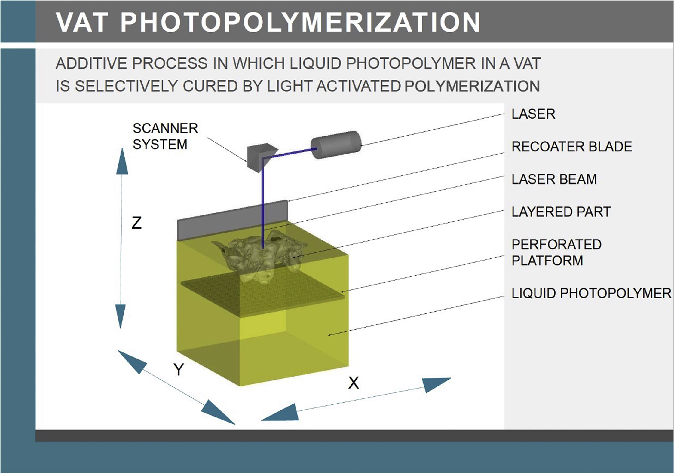
The most common forms of vat photopolymerization are stereolithography (SLA) and digital light processing (DLP). SLA has three basic components: (1) a high-intensity light source typically ultraviolet UV-A or UV-B, (2) a vat or tray that holds a photocurable liquid resin, and (3) a controlling system that directs the light source to selectively illuminate and solidify the resin. Mirrors, known as galvanometers or galvos, are located on the X- and Y-axes and these mirrors rapidly aim the laser beam across the vat curing and solidifying the resin as it goes along.
SLA machines can produce parts in two different orientations, bottom-up or top-down. Bottom-up printers have a light source positioned below a resin vat with a transparent bottom. Once a layer of the object is cured and becomes structurally stable, the object is raised by one layer, so that the next layer can be cured with the laser. For bottom-up printers, each layer may adhere to the build platform, therefore the printer performs a separation step which separates the layer from the base of the vat, before the build platform moves up one-layer thickness. Depending on the machine, this separation step may involve sliding, peeling, rotating, or shaking the vat. Bottom-up printers often have a nonstick coating (e.g., polydimethylsiloxane (PDMS) or fluorinated ethylene propylene (FEP)) applied to the base of the vat to assist with layer separation. In addition, a wiper may assist in oxygenating the PDMS/FEP coating, thus may help to improve the nonstick performance, while also ensuring that a fresh layer of resin is ready for the next layer. For bottom-up printers, another mechanism for reducing the bond forces exerted on parts during the active build layer, called Low Force Stereolithography, was recently introduced. This method uses a flexible membrane which moves in coordination with the laser location, allowing for finer detail and greater clarity. As compared to bottom-up printers, top-down printers position the light source above the build platform. The build begins at the top of the resin vat and the build platform moves down layer by layer as the object prints. A blade assembly helps to apply a fresh even coat of resin before the laser cures the next layer. For top-down printers, once the build is complete, the part is raised out of the resin, allowed to drain, and removed from the build platform.
Both top-down and bottom-up printing technologies typically require supporting structures in the form of lattices ( Fig. 5.2 ). The necessity of structural support provides stabilization of the 3D printed part within the material during the build phase. For top-down printers, the support requirements are generally used to hold up overhanging areas, whereas for bottom-up machines, the supports are more complicated as they need to be able to hold the entire weight of the build to the platform.

Instead of using a laser and mirrors to dictate the area of the resin being cured, DLP, which was originally developed in 1987 by Larry Hornbeck of Texas Instruments, uses a digital projector to instantly illuminate the entire cross section of the layer being printed. The projector is a digital screen, so the image of each layer is composed of square pixels, resulting in a layer formed from voxels. For parts which have complicated contours, DLP may be able to achieve faster print times than traditional SLA, as each layer is exposed at the same time, rather than being drawn out with a laser.
In 2017, a new method of bottom-up DLP called Continuous Liquid Interface Production (CLIP) was patented. CLIP is a photochemical process that works by projecting light through an oxygen-permeable window into a reservoir of UV-curable resin. As a sequence of UV images are projected, the part solidifies and the build platform rises. The oxygen creates a dead-zone of uncured resin at the bottom of the vat, so the bottom of the print does not adhere to the resin tank, thus the separation step is eliminated allowing for significantly faster build times. This gives the illusion that the part is building in real time with no separation between layers. Since its introduction in 2017, other companies have adopted similar techniques to speed up the manufacturing process utilizing this oxygen-permeable membrane or window principle. ,
After a model is printed with vat photopolymerization, the build platform is removed from the machine. The platform either with parts attached or the parts alone, after removal, are cleaned with a solvent, most commonly isopropyl alcohol, in a bath or parts washer. Following the cleaning process, supports generated during fabrication are removed, and the model is placed into a chamber with special lights and possibly a heat source to harden any residual resin on the surface of the model. Some resins may specify that the part should be cured before support removal to limit any warping that may occur. In addition, some materials require a postbuild heat treatment, potentially several hours, to complete the polymerization process and obtain the proper material characteristics and properties.
Materials
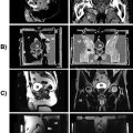
Vat photopolymerization technologies use thermoset photopolymers which come in a liquid resin form. Some of the many resin choices include characteristics such as transparency, casting ability, durability, high temperature resistance, surgical/dental usability, and flexibility. As compared to larger industrial machines, some small- to medium-sized, bottom-up desktop machines have interchangeable resin vats, thus providing an easier option to change materials, adding to the systems versatility. Specific resins and printers can allow for extra exposure of energy to specific sections of the medical models, thereby darkening or changing the color of the resin and enabling multiple structures to be depicted within a single model ( Fig. 5.3 ). Materials in this category were initially limited and were predominantly brittle; however, now there seems to be a resin for almost every application with the major advances coming in durability and flexibility.

Medical Applications
Most frequently, vat photopolymerization is used to create solid, plastic, 3D objects from medical scans or 3D designs in a matter of minutes, hours, or days to provide doctors with true-to-scale physical presurgical and planning models that they can handle and manipulate prior to procedures. As described above, dual-colored models may also be created by overcuring certain regions. Empty cavities within a model may also be created to be colored with paint or dye, thus allowing for pathology such as tumors or nerves, to be incorporated into designs. Many of the smaller bottom-up machines have become extremely popular in the dentistry industry for dental implant guides, night guards, aligners, and dentures.
Material Extrusion
Material extrusion is a process where a material is selectively dispensed through a nozzle. In most cases, heat is used to melt/soften material for the extrusion process. Melted material passes through the nozzle in a continuous stream under constant pressure and is selectively deposited onto the build tray or previous section of the printed part layer by layer ( Fig. 5.4 ). Material extrusion is commonly referred to as fused filament fabrication (FFF), and it is also widely known under a trademarked term fused deposition modeling (FDM).

The resolution of the printed part is defined by the nozzle diameter, filament diameter, and layer height. Parameters such as motor speed, part infill, extrusion speed, and nozzle temperature can be adjusted on most material extrusion machines to achieve the desired print. To save on the amount of material utilized, material extrusion parts can be printed with an internal, low-density structure known as infill. Infill percentage and shape can vary based on the application of a part as well as the type of printer being used. Common infill geometries include triangular, rectangular, and honeycomb. While the material extrusion process has many factors that may influence the quality of the final model, when these factors are controlled successfully, extremely strong and versatile parts can be produced.
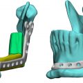
Similar to parts that are printed using vat photopolymerization, material extrusion parts require support material to print successfully, where the support material prevents the model from falling down. The support material may be printed with the same nozzle as the main model material or with a separate nozzle using a different material, some material which can be dissolved in a hot water bath or solvent (e.g., alkaline solution). If a non-dissolvable or identical material is used for the supports, then these support structures are broken away from the part manually. If an alkaline bath is used, the part is rinsed in a water bath afterward and allowed to dry. Depending on the material, support structures may only have the option to be breakaway even if they are a different material. In some cases, a part may also be oriented on the build platform so that no supports are needed. Fig. 5.5 shows a tibia model printed using material extrusion with its support structures and infill geometry.

Materials
Material extrusion printers have a wide selection of materials which are typically 1 kg spools of thermoplastic filament with a 1.75 or 3.00 mm diameter. The spools are usually shipped in shrink wrap with a desiccant to reduce humidity. It is recommended that unused filament spools be stored in a cool, dry, dark area and only opened when needed for printing. Polylactic acid (PLA) and acrylonitrile butadiene styrene (ABS) are the most common and most widely utilized materials. Some other materials include high-impact polystyrene, nylon, polycarbonate (PC), polyethylene terephthalate, polyetherimide, polyvinyl alcohol, and thermoplastic polyurethane (TPU). In addition, creative materials with infiltrates of glass and fibers are also available. Finally, metal 3D printing with material extrusion has recently become possible, and it includes a ceramic release layer between the support structures and part to enhance support removal.
Medical Applications
Most frequently, material extrusion technology is used to create monochrome plastic parts with larger anatomical features such as bones. 3D designs for assistive technology and orthotics are also commonly manufactured with material extrusion technologies. Multifilament machines have allowed medical models that include two or more materials or colors in the same build. Due to the resolution limitations and limited multicolor and multimaterial capabilities, superfine features such as smaller branch vessels are difficult to manufacture using this technology.
Material Jetting
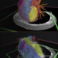
Material jetting is a process in which droplets of material, typically a liquid photopolymer, are selectively deposited onto a build platform and are cured with UV light or solidified due to ambient conditions ( Fig. 5.6 ). Similar to conventional two-dimensional ink-jet printers, material is jetted, sprayed, or extruded horizontally along the X- and Y-axes on the build surface. Most often, high-intensity UV light is used next to cure the layer of polymers allowing them to quickly transition from a liquid to solid state. This process is repeated, with each new layer bonding to the previous, until the object is complete. Some machines may use a wax and ambient temperatures in lieu of the photopolymer and light. These wax models may be used to make a cast using a burn out procedure, commonly called “lost wax.” After the build is complete, the object is removed from the platform and temporary supports are eliminated using a pressure washer, heat, or bath of basic solution. 3D printed models printed with material jetting can then be polished or coated, to achieve optimal visualization properties.
Related posts:
 An Abbreviated History of Medical 3D Printing
 Image Segmentation and Nonuniformity Correction Methods
 Regulatory Perspectives for 3D Printing in Hospitals
 3D Printed Imaging Phantoms
 3D Printed Anatomic Models and Guides
 Medical Imaging Technologies and Imaging Considerations for 3D Printed Anatomic Models
Stay updated, free articles. Join our Telegram channel

Full access? Get Clinical Tree


