4 Clinical Pictures
4.1 Shunt Defects
4.1.1 Atrial Septal Defect
Definition
The term “atrial septal defect” refers to various morphological and embryological defects of the atrial septum that in isolation, comprise a total of 5–10% of all congenital heart defects. 1 ASD often occurs in conjunction with other cardiovascular defects. Atrial septal defects should be distinguished from open PFO. Fetal atrial communication persists in approximately one-third of all children. Its clinical significance results primarily from the likelihood of paradoxical embolism of thrombi occurring from the venous area into the left systemic arterial area, and then into the aortic branches. Thrombi of this type can lead to strokes or peripheral embolisms.
Classification
The following three, most common types, will be described in detail (▶Fig. 4.1):

Secundum ASD: ASD II also known as fossa ovalis defect (approximately 70% of all ASDs), occurs in the central portion of the atrial septum with no connection to the atrioventricular valves (▶Fig. 4.1, ▶Fig. 4.2)
Primum ASD: ASD I also known as partial AVSD, comprises approximately 15–20% of all ASDs. This type of defect is situated caudally and is connected to the atrioventricular valves (▶Fig. 4.1, ▶Fig. 4.3)
Sinus venosus ASD: SVD comprising approximately 10–15% of all ASDs


Coronary sinus defect (also known as unroofed coronary sinus) is an uncommon defect type (3–5% of all ASDs).
Note
SVD often occurs in conjunction with PAPVR (see Partial Pulmonary Venous Anomalies) (▶Fig. 4.4 and ▶Fig. 4.5). Thus, once SVD has been established, it is crucial to always search for concurrent PAPVR.


Hemodynamics
An ASD allows passage of blood between the left and right atrium, also known as a “shunt.” The direction and shunt volume result from the varying compliance (elasticity) of the left and right ventricles. The right ventricle is less muscular and thus more elastic during diastole (meaning it demonstrates higher compliance) than the left ventricle. The reason for this is the low right ventricular afterload, since pulmonary arteriolar resistance comprises only approximately 10–15% of systemic arteriolar resistance, which is significant to the afterload of the left ventricle.
The left–right shunt that generally results from this phenomenon occurs primarily during late ventricular diastole and early ventricular systole. Depending on the size of the shunt, this increases or decreases volume load in the right atrium and right ventricle (▶Fig. 4.6), in addition to the pulmonary vessels (arteries and veins), which dilate accordingly (▶Fig. 4.7).


On the other hand, the left atrium retains this additional shunt volume after it passes through the lungs again. The left atrium is able to “decompress” due to the defect and is thus, in effect, not subject to volume overload (▶Table 4.1). Throughout the course of the patient’s life, the relative difference between ventricular compliance continues to increase, meaning that the left ventricle becomes increasingly inelastic as the patient ages. If an ASD is already present, this decreasing elasticity further exacerbates the left–right shunt. 3 Correspondingly, thoracic X-ray in p.-a. view depict both increased pulmonary vascular markings and a dilated pulmonary segment. The right atrium’s dilation is also expressed in the form of pronounced right atrial contour (▶Fig. 4.7a). In contrast, this dilation of the right ventricle and the RVOT are visible when taking images from lateral positions, primarily in the retrosternal area (▶Fig. 4.7 b and d).
Cardiovascular compartment | Volume load |
Right atrium | ++ |
Right ventricle | ++ |
Pulmonary arteries | ++ |
Pulmonary veins | ++ |
Left atrium | – |
Left ventricle | – |
Aorta and conduit arteries | – |
Systemic veins | – |
Clinical Issues
With the exception of bicuspid aortic valve and mitral valve prolapse syndrome, ASD is the most common heart defect diagnosed in adults (▶Fig. 4.5 and ▶Fig. 4.7). In part, this is due to the fact that the right ventricle initially handles the excess volume load well and under these conditions can also increase cardiac output.
Natural Progression and Indication for Treatment
Without treatment, clinical symptoms such as right ventricular heart failure, cardiac rhythm disorders, or progressive pulmonary arterial hypertonia 4 will begin to manifest. The indication for ASD closure is a result of studies on the natural progression of defects diagnosed later in life. 4 , 5 This data reveals that heart failure with exertional dyspnea and predominantly atrial, often difficult-to-treat tachycardic rhythm disorders occur with increasing frequency after age 30. After closure of a defect, these disorders are often irreversible. The indication for treatment is more frequently determined based on the extent of right ventricular volume load than on shunt ratio (Q p:Q s ratio) alone. 6
Treatment Options and Preinterventional Diagnostics
Catheter-based interventional closure has become possible for the majority of type II ASDs, and is widely regarded as the treatment of choice (▶Fig. 3.16 and ▶Fig. 3.17). All other types are treated surgically, which yield exceptional results. Categorizing the efficacy of various imaging procedures is based primarily on their ability to classify the ASD type precisely, and to determine the defect’s size and the dimensions of its margins compared to the surrounding cardiovascular structures. Additional diagnostic tasks include quantifying shunt volume, determining the volume’s effects on right and left ventricular function, and the morphological depiction of concurrent defects, such as anomalous pulmonary venous connections (▶Table 4.2). Precise, noninvasive quantification of shunt volume by determining the Q p:Q s ratio—meaning the cardiac output measured in the pulmonary artery (index “P”) and aorta (index “S” = systemic artery)—is one application of MRI flow measurement (▶Fig. 4.8). 7 , 8

Postoperative and Postinterventional Issues
Rhythm disorders and, in extremely rare cases, cyanosis concurrent with inferior ASD (occasionally with the option to shunt the lower caval vein into the left atrium) are among the issues that may occur after surgical or interventional ASD corrections. 9
Goals and Relative Value of Diagnostic Imaging
TTE is generally sufficient for preoperative diagnostics in children. 7 For adults, a thoracic X-ray may also be ordered due to morphological signs suggesting an ASD that are typically visible via imaging (▶Fig. 4.7). TEE plays a central role for older children and adults. Clinical practice has shown that especially for these older patients with ASDs cardiac MRI is selected more and more frequently as the first-choice method. 10 , 11 For younger children, however, tomographic procedures are used only rarely, and generally only as a backup method for echocardiography or for postinterventional follow-up exams (▶Table 4.2 and ▶Table 4.3). MRI has a special role, and CT has a backup role for visualizing a PAPVR within the scope of an SVD (▶Fig. 4.4). In particular, preparing multiplanar reformats of a 3-D MRA or of an MDCT data set (▶Fig. 4.5) facilitates preoperative planning. One particular strength of MRI is its ability to measure shunt volume noninvasively (▶Fig. 4.8) via flow measurement (using the phase contrast technique) in the aorta and pulmonary artery to calculate Q p:Q s ratios.
4.1.2 Ventricular Septal Defect
Definition
The term “ventricular septal defect” encompasses various morphological and embryological defects of the interventricular septum. Comprising a total of 15–20% of all congenital heart defects, VSDs are the most common. This does not include VSD that is very commonly concurrent with complex heart defects (especially cyanotic ones). Thus, VSD occurs in isolation in 90% of cases. 12 Classification is based on morphological criteria and takes into account the division of the ventricular septum into a pars membranacea and a pars muscularis. Also note that the tricuspid valve and its septal leaflet attach to the septum somewhat closer to the cardiac apex (provided no atrioventricular canal resulting from an endocardial cushion defect is present), which results in the ability to create a connection between the left ventricle and right atrium near this “atrioventricular septum.”
Classification
In principle, all membranous and muscular parts of the ventricular septum could be affected by a VSD. From a morphological or topographical perspective, the ventricular septum possesses an inlet segment near the cardiac base, a right ventricular trabeculated section that includes the apex cordis, and an outlet segment near the outflow tract toward the outlets of the great arteries (▶Fig. 4.9).

The trabeculated segment of the muscular ventricular septum can be further subdivided into the central, marginal, and apical portions (▶Fig. 4.14). This is significant to the extent that ventricular septal defects are generally described based on their anatomical position and their topographic and anatomical spatial relations (e.g., their position with respect to the atrioventricular valves or great arteries), since this type of classification results in various strategies for interventional treatment.
Classification of a VSD (▶Fig. 4.9):
Type A: Perimembranous (or subaortic) VSDs occurs (▶Fig. 4.10 and ▶Fig. 4.11) immediately inferior to the aortic valve in 70% of cases. Larger perimembranous or paramembranous VSDs are not limited to just the membranous portion, but also extend to the inlet septum, trabeculated septum (▶Fig. 4.12), or outlet septum.
Type B: A subpulmonary VSDs (▶Fig. 4.13) are located in the supracristal portion of the membranous ventricular septum and thus in the outlet septum. This defect is not infrequently complicated by the right coronary aortic cusp prolapsing into the VSD (▶Fig. 4.13), which can lead to progressive aortic valve insufficiency.
Type C: A muscular VSDs (approx. 10% of all VSDs) are fully surrounded by muscle and can occur anywhere in the muscular portion of the interventricular septum (▶Fig. 4.14). Hybrid forms can also occur.


Note
An inlet VSD (▶Fig. 4.12) affects the same section of the septum as the VSD portion in cases of complete AVSD.
Membranous VSDs (types A and B) constitute 90% of all VSDs.
Special forms:
Atrioventricular canal VSD (approximately 6% of all VSDs) is handled separately in Chapter 4.1.3, Atrioventricular Septal Defect.
Malalignment VSD is categorized as a conotruncal defect (▶Fig. 4.10).
Gerbode VSD is a defect of the atrioventricular portion of the membranous septum. This results in a shunt between the left ventricle and right atrium. This may be due to the fact that the tricuspid valve and its septal leaflet attach a few millimeters further apically toward the membranous portion of the septum than the mitral valve on the other side of the ventricular septum. This disparity causes a hemodynamic change compared to other types of VSDs (see below and ▶Table 4.4).
Hemodynamics
For patients with isolated VSDs, clinical symptoms depend both on the defect’s size and the ratio of downstream pulmonary and systemic vessel resistance. The anatomical position of the VSD is, in contrast, less crucial. 12 , 13
In normal situations with low pulmonary arteriolar resistance, a left–right shunt occurs primarily during systole. During the contraction phase, the pulmonary artery supplies it directly, thus causing no volume overload in the right ventricle (▶Fig. 4.11 and ▶Fig. 4.13). Rather, this load is borne by the pulmonary vessels and left side of the heart. These cardiovascular structures can also dilate accordingly as a result of the volume overload (▶Table 4.4).
A very small defect is restrictive, and the shunt is, consequently, rather minor. A larger VSD can still release pressure, but the shunt remains largely relevant, provided that pulmonary arteriolar resistance is normal. A large VSD can cause pressure between the ventricles to equalize. In cases of normal pulmonary arteriolar resistance, this leads to heart failure due to massive left–right shunt with critical reduction of systemic cardiac output. If anatomical stenoses of the RVOT, pulmonary valve, or pulmonary vessel bed are also present, the left–right shunt will malfunction less critically, and heart failure generally will not occur.
Long-term exposure of the pulmonary vessel bed to pressure and volume overload can develop into a progressive and ultimately irreversible increase in pulmonary arteriolar resistance. In the most extreme cases, this is known as “Eisenmenger syndrome.” This can even cause shunt reversal with the development of cyanosis. This risk increases significantly after the first year of life. Thus, for cases of pressure-equalized VSDs, the defect should be closed beforehand.
Note
Cases of Gerbode defect result in a special hemodynamic situation, since this syndrome causes volume overload in the right atrium and ventricle. In contrast, restrictive defects of the other portions of the septum (as already mentioned) do not cause volume overload of the right atrium and ventricle, even if a large shunt volume is present.
Clinical Issues
Small VSDs are often first diagnosed in adulthood. Due to dyspnea and limited exercise capacity, larger defects are often noted during infancy as signs of cardiac failure, often within the scope of bronchopulmonary infections. 12 Cyanosis does not occur until after shunt reversal (Eisenmenger syndrome).
Natural Progression and Indication for Treatment
Most patients with isolated, small- to medium-sized VSDs have a good prognosis, especially since spontaneous decreases in size up to full regression can occur in up to 50% of patients, 13 primarily in cases of muscular VSD. The indication for treatment is determined primarily by a shunt ratio (Q p:Q s ratio) of 1.5:1 to 2:1, and/or if pulmonary arterial pressure increases to half that of systemic values. 12 Symptomatic children with large VSDs receive surgical treatment within the first 6 months of life, while asymptomatic children with pressure-separating VSDs but relevant left–right shunt volume, are treated already as toddlers. Additional indications for surgery include pressure-separating defects without relevant shunts if the right coronary aortic cusp prolapses into the VSD, particularly in cases of subpulmonary VSD position (▶Fig. 4.13), causing asymmetry of the aortic valve and aortic valve insufficiency.
Treatment Options and Preinterventional Diagnostics
Catheter interventional closure is primarily possible for muscular VSD, though it is fundamentally possible for cases of membranous VSD, as well. Especially in cases of Swiss cheese ventricular septum with multiple muscular VSDs, graduated treatment is often necessary. This entails a palliative surgical treatment by means of pulmonary artery banding, followed by a combined interventional surgical procedure, to be completed in tandem. For cases of large, isolated VSDs, surgical closure is the first-choice procedure and is generally performed from the right atrium from a trans-tricuspid view using a Dacron patch. Nowadays, trans-infundibular access is generally avoided.
Classifying the efficacy of the various imaging procedures prior to an intervention is based on the procedures’ ability to precisely determine size, visualize the localization, and quantify shunt volume and its effects on left and right ventricular function. Fundamentally, the VSD can already be visualized well using echocardiography (▶Fig. 4.10, ▶Fig. 4.11, ▶Fig. 4.13 and ▶Fig. 4.14). 3-D echocardiography, in particular, is especially helpful for peri-interventional and perioperative planning. Not infrequently, TEE is the final, decisive diagnostic method for particular constellations, such as Gerbode defect or aortic valve prolapse in cases of subpulmonary VSD (▶Fig. 4.13). Precise, noninvasive quantification of shunt volume by determining the Q p:Q s ratio remains within the domain of MRI flow measurement (▶Fig. 4.8) 7 , 8 in cases of both ASD and VSD, provided no other valve defects are present. Shunt volume can also be estimated by comparing right and left ventricular SV as determined using volumetric analysis. This is, however, generally less precise than MR flow measurement. Estimating shunt volume by comparing right and left ventricular SV is also possible using retrospective ECG-triggered MDCT, but is only reasonable if the examination is necessary because of another indication (e.g., to assess the coronary arteries noninvasively) due to the high radiation exposure. 7
Postoperative and Postinterventional Issues
Repeated imaging is only reasonable within the scope of concurrent defects or if a residual shunt is suspected (e.g., for quantification via MRI flow measurement). Residual defects can often be characterized in older children and adults using TEE, excellent results.
Goals and Relative Value of Diagnostic Imaging
Like in ASD patients, TTE is generally sufficient for assessing VSDs in preoperative diagnostics during childhood, 7 and can be supplemented by TEE. In cases of an inadequate acoustic window—particularly in adults—MRI visualization, MRI shunt quantification, and MRI ventricular volumetry are valuable diagnostic alternatives for cases of VSD, both for primary diagnosis and for follow-up exams.
4.1.3 Atrioventricular Septal Defect
Definition
The term “atrioventricular septal defect” (formerly known as “endocardial cushion defect”) encompasses congenital cardiac defects of the structures derived from the embryonic endocardial cushion, meaning from the atrioventricular septum and parts of the mitral and tricuspid valves. They constitute approximately 2–4% of all congenital heart defects. 12 Characteristics of these defects include a joint atrioventricular valve annulus (▶Fig. 4.15) with either a single joint opening or two separate openings, a VSD of variable size, and an ASD I. 13

In the most severe anomalies within this group, the primum septum and inlet ventricular septum are completely absent. This means that all chambers of the heart are connected, which was previously known as “total atrioventricular canal” (▶Fig. 4.15).
Note
Trisomy 21 is present in 50% of patients with complete AVSD.
Classification
Signs of all AVSDs:
Lack of membranous atrioventricular septum
Joint atrioventricular valve annulus with joint or two separate openings
Reduced distance between the atrioventricular valve and cardiac apex
Superior displacement and lengthening of the LVOT This is also known as a “goose-neck deformity” of the LVOT. In these cases, there is no fibrous aorto-mitral continuity. This stenosis or deformation of the LVOT is most pronounced during diastole, caused by the lack of atrioventricular border normally provided by the membranous septum. 14
The following, most common types will be discussed in detail:
Complete AVSD (most common type): A 4-leaflet or 5-leaflet atrioventricular valve (ostium commune) is present (with superior and inferior bridging leaflet), which extends to both ventricles via the septal defect (▶Fig. 4.15). The division of the joined atrioventricular valve via both ventricles can be either balanced (▶Fig. 4.16a, b and, c) or unbalanced (▶Fig. 4.16a, b). This generally leads to hypoplasia in the contralateral ventricle. 15 The superior bridging leaflet may divide near the septum, resulting in a 5-leaflet joint atrioventricular valve. According to Rastelli, balanced, complete AVSD is further subclassified based on the degree of bridging of the anterior or superior bridging leaflet:
Type A (70% of cases) with further subdivision of the anterior leaflet into a superior bridging leaflet and a well-developed (right) anterior–superior leaflet; the left tendinous cords insert into the superior margin of the ventricular septum;
Type B (15% of cases) with further subdivision of the anterior leaflet into a superior bridging leaflet extending far to the right, and a small anterior–superior leaflet; the left tendinous cords insert into the right papillary muscle;
Type C (15% of cases) with no subdivision of the anterior leaflet; the bridging leaflet is large and extends to the right mural leaflet, while the anterior–superior leaflet is absent, resulting in complete bridging (▶Fig. 4.15b).
Partial AVSD (second most-common type): ASD I with “cleft formation” in the anterior “mitral leaflet” is present near the atrioventricular valve (known as mitral cleft; ▶Fig. 4.17).
Intermediate AVSD (also known as transitional AVSD): The complete atrioventricular canal demonstrates restrictive or functionally closed VSD components caused by portions of the joined atrioventricular valve. 15
AVSD: This is a rare, special form of a muscular inlet VSD situated directly inferior to the atrioventricular valves.
Isolated mitral valve cleft: This rare form can be considered the least severe form of AVSD with an intact septum.


Hemodynamics
The hemodynamics of complete AVSD are characterized by a generally large left–right shunt with pulmonary “recirculation.” The shunt volume at the level of the ventricle thus depends primarily on pulmonary vascular resistance. The VSD is generally large and non-restrictive. Thus, few symptoms are usually present in newborns. With the drop in pulmonary vascular resistance at the age of 6–8 weeks, the left–right shunt increases at the level of the ventricle, which generally leads to early development of global congestive heart failure with pulmonary overflow and left ventricular volume overload (▶Fig. 4.18). If untreated, AVSD can develop into a correspondingly early fixed pulmonary hypertension and triggering of Eisenmenger reaction.


The hemodynamic situation of a partial AVSD is similar to that of an ASD with volume overload occurring in the right ventricle and pulmonary arteries. Furthermore the extent of mitral valve regurgitation determines the hemodynamics. (▶Fig. 4.19 and ▶Table 4.5).

Cardiovascular compartment | Volume load |
Right atrium | ++ |
Right ventricle | ++ |
Pulmonary arteries | ++ |
Pulmonary veins | ++ |
Left atrium | ++ |
Left ventricle | ++ |
Aorta and conduit arteries | – |
Systemic veins | – |
Clinical Issues
In cases of complete AVSD and large left–right shunt, global heart failure generally occurs within a few weeks (▶Fig. 4.18). Within the first year of life, irreversible remodeling of the pulmonary vasculature due to the pulmonary overflow develops. Symptoms are generally less pronounced in cases of partial AVSD, and manifest heart failure rarely develops within the first year of life.
Natural Progression and Indication for Treatment
All AVSDs constitute an indication for surgery, regardless of the type of AVSD. 13
Note
For balanced forms, one should always attempt to enable complete biventricular correction by means of valve reconstruction.
For premature babies, very small children, or patients with concurrent illnesses, pulmonary banding can be performed as a palliative method before surgical correction. The development of a left atrioventricular valve insufficiency with enlargement of the cleft is unfavorable for reconstruction. Thus, the presence of left valve insufficiency (▶Fig. 4.20) constitutes an indication for surgery, regardless of symptoms. In cases of unbalanced AVSDs, univentricular palliation must be performed.

Preoperative Diagnostics
Particularly in cases of complete AVSD, thoracic X-ray (▶Fig. 4.18) indicate significant cardiac enlargement with a prominent pulmonary segment and increased pulmonary vascular markings. These changes are, however, nonspecific. TTE is the initial method of choice, since it allows the atrioventricular valves and bridging leaflet to be depicted via the septal defect. The goose-neck deformity can be visualized in an LVOT cross-section. TEE is the predominant method used for larger children and adults. Cardiac MRI can be used in cases of a limited acoustic window (▶Fig. 4.16 and ▶Fig. 4.18), which also allows shunt volume to be calculated by determining the Q p:Q s ratio. CT plays no role in preinterventional diagnostics. Invasive levocardiography and dextrocardiography also allow pulmonary pressure to be measured, in addition to providing anatomical depictions. They have, however, been largely replaced by echocardiography and MRI in routine preoperative diagnostics, and are performed primarily for late-diagnosed AVSD in order to evaluate pulmonary vascular responsiveness (or after pulmonary banding was performed at a later date, on a case-by-case basis).
Postoperative Issues
The main perioperative and postoperative issues are generally transitory pulmonary vessel reactivity or hypertension, incomplete closure of the defect, atrioventricular blocking, and residual atrioventricular valve insufficiency. If the valves cannot be adequately reconstructed, the atrioventricular valve must be replaced.
Goals and Relative Value of Diagnostic Imaging
As mentioned previously, TTE is sufficient for preoperative diagnostics during childhood (▶Table 4.6). 7 TEE is ideal after surgery and for adults. MRI can be useful in cases of limited acoustic window, either for visualizing concurrent defects or for quantifying shunt volume (▶Table 4.7).
4.1.4 Patent Ductus Arteriosus
Definition
PDA (also known as patent ductus arteriosus) is the persistence of the fetal connection between the intrapericardial portion of the main pulmonary artery or proximal left pulmonary artery and the extrapericardial descending aorta immediately after the outlet of the left subclavian artery. 12 PDA is a common congenital heart defect, generally concurrent with other congenital defects in 5–10% of patients, though is more frequent in girls than in boys. From an embryological perspective, it develops from the distal portion of the left sixth aortic arch (▶Fig. 4.21c; right aortic arch: ▶Fig. 4.21a). 13 Approximately 60% of cardiac output flows through this arch. This duct normally closes within 72 hours after birth.

Classification
A clinical distinction is made between the following four forms of PDA 13 :
Incidental finding in cases of complex defects (common)
Isolated form in premature babies (common; ▶Fig. 4.22)
“Compensating” PDA in cases of ductal-dependent heart defects, such as HLHS (ductal-dependent systemic perfusion) or hypoplastic right heart syndrome (ductal-dependent pulmonary perfusion, e.g., in cases of pulmonary atresia)
Isolated form in otherwise healthy children (rarer)

In very rare cases, a duct aneurysm can occur in a duct with isolated pulmonary (but not aortic) closure (▶Fig. 4.23).

From pathological and anatomical perspectives, different variants are possible, including those dependent on the presence of a left or right aortic arch. 14 Bilateral PDA can also occur (▶Fig. 4.21b and d), though only in extremely rare cases.
Hemodynamics
An isolated PDA causes a left–right shunt. In these cases, the shunt’s size depends on the diameter of the PDA and the difference between systemic and pulmonary arteriolar resistance. If the PDA diameter is large enough, the left–right shunt generally increases in size during the first months of life. 13 In cases of a particularly large PDA with pressure equalization, if no closure between the aorta and pulmonary artery occurs within the first 6–12 months of life, there is a risk of progressive, often irreversible disorders of the pulmonary resistance vessels accompanied by increased pulmonary vessel resistance. This can lead to shunt reversal (also known as Eisenmenger syndrome). ▶Table 4.8 depicts volume load.
Cardiovascular compartment | Volume load |
Right atrium | – |
Right ventricle | – |
Pulmonary arteries | ++ |
Pulmonary veins | ++ |
Left atrium | ++ |
Left ventricle | ++ |
Aorta (proximal to the PDA) | ++ |
Systemic veins | – |
Clinical Issues
Clinical signs of cardiac failure include a tendency toward infections, sweating, difficulty drinking, and growth disorders, and occur in early infancy solely in cases of extremely large PDA. Generally speaking, the concurrent illnesses remain predominant.
Natural Progression and Indication for Treatment
If untreated, isolated PDA is associated with a 30% mortality rate.
Note
Spontaneous closure after the first weeks of life is extremely rare in mature newborns. Consequently, it is crucial to strive for interventional closure within the first months of life, even in asymptomatic patients.
Treatment must occur as soon as possible for symptomatic newborns. Since indomethacin is no longer effective for mature newborns, it cannot be used in treatment. Rather, a surgery or intervention is needed. Interventional closure using coils, spirals, or a shield system has become the treatment method of choice (▶Fig. 4.24 and ▶Fig. 4.25). Only very large PDAs or duct aneurysms generally require surgical closure (▶Fig. 4.23).


Preinterventional Diagnostics
Generally speaking, PDA can be visualized clearly using Doppler echocardiography along a high (second-left intercostal area) parasternal short axis. This generally depicts three vessels in proximity to the main pulmonary artery branch: the PDA, and the left and right pulmonary arteries (▶Fig. 4.22). Contrast-enhanced MRA also yields clear images (▶Fig. 4.26a). In cases of a small PDA, a cine MRI through the pulmonary artery and aorta (▶Fig. 4.26b), which allows the PDA to be detected due to MR dephasing caused by flow acceleration of the PDA via the left–right shunt, can also be helpful. MR flow measurement can be used for noninvasive shunt quantification in the ascending aorta, pulmonary artery, or distal to the PDA in the right and left pulmonary arteries. MDCT, likewise, can be used as a backup method (▶Fig. 4.23).

Postoperative and Postinterventional Issues
A residual shunt can occur after surgical or interventional closure. Generally speaking, this can be evaluated via echocardiography. MRI using phase contrast technology is an alternative for quantifying any potential residual shunt.
Goals and Relative Value of Diagnostic Imaging
TTE is generally sufficient during childhood (▶Table 4.9 and ▶Table 4.10). 7
4.1.5 Aortopulmonary Window (Aortopulmonary Septal Defect)
Definition
APSD—also known as “aortopulmonary window,” “aortopulmonary septal defect,” and “aortopulmonary fistula”—is a very rare defect caused by an embryonic defect in the aortopulmonary septum. It can occur in isolation or concurrent with other congenital heart defects, such as coronary anomalies (in 50–66% of cases). This defect causes a connection of varying size between the ascending aorta and pulmonary artery (▶Fig. 4.27). In these cases, two separate valve rings for the aortic and pulmonary valve are always present.

Classification
A rough distinction can be made between the proximal and distal types 13 :
Proximal defect (62% of APSDs; ▶Fig. 4.28, ▶Fig. 4.29, and ▶Fig. 4.30; also ▶Fig. 4.27a): The APSD is located on the dorsal-lateral or posterior wall of the ascending aorta or the anterior-lateral wall of the pulmonary artery, meaning that the defect is directly cranial to the aortic and pulmonary valves.
Distal defect (38% of APSDs; ▶Fig. 4.31; also ▶Fig. 4.27b): The APSD is located near the anterior wall of the right pulmonary artery. Very large defects may appear to be right pulmonary arterial outlets from the ascending aorta (hemitruncus). Unlike hemitruncus, however, a connection remains between the right pulmonary artery and the pulmonary arterial bifurcation.


Hemodynamics
Generally speaking, the APSD is large, meaning that it does not lead to pressure separation (restriction). In this respect, the APSD bears a pathophysiological resemblance to a large, window-like PDA. Nevertheless, it generally leads to earlier occurrence of heart failure (▶Fig. 4.32), similar to cases of small children with large VSDs. If untreated, large APSDs can lead to fixed pulmonary hypertension and the Eisenmenger reaction. Volume load in cases of APSD is listed in ▶Table 4.11.

Cardiovascular compartment | Volume load |
Right atrium | – |
Right ventricle | – |
Pulmonary arteries | ++ |
Pulmonary veins | ++ |
Left atrium | ++ |
Left ventricle | ++ |
Aorta and conduit arteries | – |
Systemic veins | – |
Clinical Issues
Within the scope of pronounced left–right shunt with pulmonary overflowing, children generally exhibit a failure to thrive, recurrent pulmonary infections, and the clinical picture of heart failure (▶Fig. 4.32).
Natural Progression and Indication for Treatment
Due to the poor prognosis for untreated defects (with the exception of small shunts), diagnosis is generally a sufficient indication for surgery. 13 A contraindication for surgical treatment only exists in cases where the Eisenmenger reaction has already occurred. For smaller defects, surgeons can also strive for interventional closure.
Preinterventional and Preoperative Diagnostics
In general, TTE is adequate (▶Fig. 4.30 and ▶Fig. 4.31) for diagnostic purposes in children, especially in cases of proximal defects (▶Fig. 4.30). In cases of distal defects, visualization can present difficulties. A cross-sectional imaging procedure, ideally an MRI, can be useful in such situations (▶Fig. 4.28 and ▶Fig. 4.29). In addition to visualization, MRI also allows absolute shunt quantification. MDCT is also, fundamentally, appropriate for visualizing defects, particularly if additional coronary and/or aortic anomalies are present or suspected.
Postoperative and Postinterventional Issues
Post-surgical prognosis is generally determined by concurrent defects and the degree of pulmonary hypertension. Similar to the closure of small defects, if the APSD is surgically treated within the first year of life—namely, before the onset of irreversible pulmonary changes—life expectancy is fully unaffected. 12
Goals and Relative Value of Diagnostic Imaging
TTE is generally sufficient during childhood (▶Table 4.12 and ▶Table 4.13). 7 Fluoroscopy can also be used to monitor peri-interventional catheter placement (▶Fig. 4.33).

4.2 Right-Side Defects
4.2.1 Pulmonary Valve Stenosis
Definition
Isolated pulmonary valve stenosis is the most common form of narrowed RVOT in cases of normal aortic origins (occurring in 80% of cases). It constitutes 6–8% of all congenital heart defects. 16 There are various clinical progressions based on the degree of stenosis, which are generally caused by adhesion of the tricuspid or bicuspid semilunar valves’ commissures (▶Fig. 4.34).

Natural Progression and Clinical Issues
If a moderate-to-severe pulmonary valve stenosis (▶Table 4.15) is present, blood flow into the lungs is reduced, resulting in the development of cyanosis and ductal-dependent pulmonary blood flow. This clinical picture is then described as “critical pulmonary stenosis.” In these cases, hypoplasia of the corresponding hypertrophied right ventricle is often also present.
In contrast, if only a minor degree of stenosis is present, diagnosis often first occurs based on systolic heart murmur or when signs of right ventricular heart failure arise. Fully unremarkable clinical progressions can also occur, meaning corresponding diagnostics only occur based on pathological ECG findings.
Treatment Options and Preinterventional Diagnostics
Nowadays, interventional catheter therapy using balloon valvuloplasty (▶Fig. 4.36) is performed in the vast majority of cases of symptomatic, isolated pulmonary valve stenosis, which can generally be quantified clearly via Doppler echocardiography (▶Fig. 4.35; ▶Table 4.15)—meaning starting at a gradient of more than 3–40 mmHg in clinical practice. This can be performed even in newborns at very low risk. Surgical treatment is only used in very rare cases, often after unsuccessful balloon dilatation or in cases of pronounced dysplasia of the valve apparatus and/or associated subvalvular or supravalvular narrowing. This operation is often combined with narrow transannular patch plasty. 17

Postoperative and Postinterventional Issues
Patients with pulmonary valve stenosis who were initially treated successfully using balloon valvuloplasty may develop new gradients or possess a residual gradient that must be monitored to assess the need for additional treatment. A residual peak gradient of less than 20–30 mmHg is generally well tolerated. 18 The prominent pulmonary segment, often first identifiable in the p.-a. thoracic X-ray, frequently remains present even after successful treatment (▶Fig. 4.37).
Pulmonary valve insufficiency and the corresponding right ventricular volume overload occasionally occur after balloon dilatation. Much more commonly, they occur after surgical treatment. Consecutive right ventricular dilatation, which patients may tolerate well for years (▶Fig. 4.37b and ▶Fig. 4.45), can later lead to progressive tricuspid valve insufficiency and electrical instability, resulting in ventricular arrhythmia and right ventricular heart failure.
Note
The main objective of imaging is determining the timing of the interventional or surgical pulmonary valve replacement, which should occur based on objective progression data.
Goals and Relative Value of Diagnostic Imaging
Both initial diagnosis of a congenital pulmonary valve stenosis and the indication for interventional or surgical treatment can generally be depicted very well using doppler echocardiography (▶Fig. 4.35). MRI and MDCT play a large role, above all during postsurgical and postinterventional follow-up care. MRI is the method of choice for assessing right ventricular function, volume, and mass (▶Table 4.14). It is also suitable for absolute quantification of pulmonary valve insufficiency (▶Fig. 4.37) by means of calculating the regurgitation fraction:

where
RF = regurgitation fraction in %
Antegrade and retrograde flow are indicated in ml.
MDCT allows concurrent changes to pulmonary structure and vascular changes caused by CTA (such as MAPCA and peripheral pulmonary stenosis) to be depicted (▶Fig. 4.46). Vascular changes can also be depicted clearly using contrast-enhanced MRA (▶Fig. 4.38). Dynamic visualization of the valve can also be performed via MDCT when using retrospective gating. Due to high radiation exposure, however, this method only comes into play in cases of inadequate acoustic windows and contraindications for MRI diagnostics. 7 MRI, in contrast, can be used as an alternative to echocardiography, while CT can only be used in certain cases, e.g., to assess a lung parenchyma. Likewise, a valve stenosis can be quantified noninvasively via Doppler echocardiography, MRI flow measurement, or valve planimetry (▶Table 4.15; also ▶Fig. 4.37).
4.2.2 Tetralogy of Fallot
Definition
In 1888, Etienne-Louis Arthur Fallot described a combination of pulmonary stenosis, large VSD, and right displacement of the aorta with concentric right ventricular hypertrophy (▶Fig. 4.39). 19 Nowadays, anterior cephalic malrotation of the outlet septum is considered the main cause of this most common cyanotic defect, comprising up to 9% of all heart defects in international literature, and 2.5% of all cardiac defects in Germany in the 2006-07 year. 16
Natural Progression and Clinical Issues
Similar to isolated pulmonary valve stenosis, the degree of stenosis of the RVOT determines the clinical symptoms, which can range from severe cyanosis with ductal-dependent pulmonary perfusion to the clinical picture of “pink Fallot.” The commonly present infundibular (i.e., muscular) portion of an outflow tract stenosis (▶Fig. 4.40) can lead to intermittent bouts of cyanosis, even in cases of minor or moderate pulmonary stenosis. The pulmonary arteries also demonstrate variable pathology. Stenoses, particularly those of the left pulmonary artery, are common and can lead to side differences in pulmonary perfusion (▶Fig. 4.41). Hyperperfusion can also occur in certain pulmonary segments due to aortopulmonary collaterals (▶Fig. 4.42). 20
Treatment Options and Preinterventional Diagnostics
In cases of ductal-dependent pulmonary blood flow, catheter interventional procedures using balloon dilatation of valvular stenosis portions can be used (▶Fig. 4.36). If cyanotic newborns cannot be treated using catheter procedures, either an aortopulmonary shunt is placed or early correction is performed. In cases of elective correction, generally during the first 6 months of life, the VSD is closed and the outflow tract stenosis is addressed by resecting the obstructing bundle of muscle in conjunction with a valvuloplasty. This procedure is commonly supplemented by a transannular patch due to the often-narrow valve rings. Like in cases of isolated pulmonary valve stenosis, preinterventional diagnostics fall within the domain of Doppler echocardiography (▶Fig. 4.35 and ▶Fig. 4.39d).


Postoperative and Postinterventional Issues
During surgical correction of RVOT stenosis, a dilemma arises between moderate widening of the outflow tract with the risk of a relevant residual gradient, and considerable expansion using a patch (▶Fig. 4.43 and ▶Fig. 4.44), which carries the risk of significant pulmonary valve insufficiency. Higher perioperative mortality in cases of significant residual gradients leads to increased use of transannular patches. Similar to isolated pulmonary valve stenosis, right ventricular volume overload is generally well tolerated, sometimes for decades. The timing for a secondary pulmonary valve replacement has changed in recent years due to multiple studies for adult patients, where no regression of a right ventricular dilatation beyond 170–180 ml/m2 could be proven. 21 In cases of right ventricular dilatation, a pronounced tricuspid valve insufficiency may develop, which will then require further treatment (▶Fig. 4.45).

Pulmonary arterial stenoses are common after surgery (▶Fig. 4.40, ▶Fig. 4.41, and ▶Fig. 4.43), and the use of foreign materials during primary correction renders them more common. Today, they remain within the domain of catheter interventional treatment. They are generally well managed via balloon dilatation and stent implantation. 20 , 22


Goals and Relative Value of Diagnostic Imaging
Like in cases of isolated pulmonary valve stenosis, Doppler echocardiography is the initial method of choice for diagnostic purposes and for determining indication for surgery (▶Table 4.16). In cases where the peripheral pulmonary arterial branches can only be assessed on a limited basis through the pulmonary parenchyma or where MAPCAs are present, MRI and MDCT imaging procedures using contrast-enhanced angiography (▶Fig. 4.46; also ▶Fig. 4.38 and ▶Fig. 4.42) can be helpful before electing to use an invasive cardiac catheter. The main focus of tomographic procedures, especially MRI, is postoperative use. Monitoring progression requires consistent assessment of right ventricular function, volume, and muscle mass with respect to residual stenosis and pulmonary valve insufficiency (▶Fig. 4.37) in order to be able to determine indications for additional surgery. In the meantime, specific reference values for the expected ventricular sizes and dimensions of the great vessels (in both cases, based on the patient’s age and sex) are available for these heart defects. 23 – 25


Newer interventional procedures, such as transcatheter valve replacement (▶Fig. 4.44), require precise preinterventional assessment of the ventricle that underwent previous surgical treatment, RVOT, valve annulus, and the pulmonary valve, itself. This can occur via MRI or MDCT (▶Fig. 4.43), especially if there is a contraindication against MRI (e.g., if an implantable cardioverter defibrillator [ICD] is present).

4.2.3 Pulmonary Atresia with Ventricular Septal Defect and Intact Ventricular Septum
Definition
Pulmonary atresia with VSD (approx. 1% of all heart defects 16 ) can be described as an extreme variant of tetralogy of Fallot, in which complete closure of the RVOT to the lungs occurs (▶Fig. 4.42 and ▶Fig. 4.46). The aorta is displaced similarly to cases of tetralogy of Fallot, and the VSD is generally large. Pulmonary perfusion occurs via the ductus arteriosus or multiple aortopulmonary collaterals, the MAPCAs. 26
In cases of pulmonary atresia with intact ventricular septum (approx. 0.5–1.0% of all heart defects 16 ), complete closure of the RVOT to the lungs also occurs. The blood in the right ventricle cannot drain through a ventricular septal defect. Thus, significant hypoplasia of the right ventricle’s greatly thickened walls often occurs in this situation (▶Fig. 4.47). Associated anomalies of the tricuspid valve are common. Connections may also arise between the right ventricle (which is subjected to significant pressure overload) and the coronary arteries, which further complicates surgical treatment. 27 In both situations, additional atrial septal defects are often present.

Natural Progression and Clinical Issues
The lack of antegrade pulmonary perfusion is common in both types of heart defects. Clinical status after birth is determined primarily based on the type of pulmonary perfusion and the location of the central pulmonary arteries. If a fairly normal pulmonary arterial system is present and pulmonary perfusion occurs mostly via the ductus arteriosus, the duct is held open using prostaglandin. If, as is generally the case, multifocal pulmonary circulation occurs via individual MAPCAs (▶Fig. 4.42), attempts to hold open the ductus arteriosus are generally unsuccessful. This causes differing pulmonary circulation in the different pulmonary lobes, resulting in the development of heart failure and increased resistance in these pathological vessels.
Note
In cases of pulmonary atresia with intact ventricular septum (▶Fig. 4.47a), an adequate atrial shunt is of great importance, since this is the only way to reintroduce systemic blood into circulation.
Treatment Options and Preinterventional Diagnostics
For both types of heart defects, if a membranous pulmonary atresia is present, there is a possibility of antegrade, catheter interventional or surgical opening, provided that the central pulmonary arteries are normal. The presence of a right ventricle that is adequately large or capable of development is a prerequisite for these procedures. Particularly for cases of pulmonary atresia with intact ventricular septum, pronounced hypoplasia in the right ventricle renders biventricular correction impossible. As a result, treatment must take the form of definitive palliation in the sense of Fontan circulation. The sections on HLHS and univentricular heart address this topic in greater detail. If an adequately large ventricle is present, biventricular correction is desirable. If multiple MAPCAs are present, they must be combined surgically (i.e., unifocalized) in order to ensure antegrade pulmonary perfusion after implanting a conduit (valve-equipped [▶Fig. 4.48] or valve-less) and in order to be able to close the VSD.

Postoperative and Postinterventional Issues
Stenosis of the consolidated pulmonary arteries often occurs after unifocalization and biventricular correction. In some cases, certain pulmonary areas receive both antegrade perfusion and perfusion from the residual MAPCAs (i.e., double perfusion). Individual pulmonary segments can only be supplied with blood by aortopulmonary collaterals, which elevates the risk of developing pulmonary arterial hypertonia in these areas. 28
After biventricular correction, cardiac function for the right chamber is determined by frequent pressure elevation due to the newly created central pulmonary vascular system, the sometimes abnormally formed peripheral pulmonary vascular system, and the function of the implanted conduit. The persistence of significant MAPCAs can cause volume overload in the left ventricle.
Goals and Relative Value of Diagnostic Imaging
Doppler TTE is the primary method of choice in preoperative diagnostics, including in cases of pulmonary atresia with and without VSD (▶Table 4.17). In order to assess aortopulmonary collaterals, additional imaging is often necessary. Imaging procedures can be performed in vasively if interventional measures or additional parameters that can only be acquired via invasive procedures are scheduled, or by means of contrast-enhanced MRA and CTA. If appropriate protocols are used, radiation exposure from CTA can be lower than that from an invasive cardiac catheter examination. The significance of noninvasive cross-sectional imaging becomes most apparent in postoperative follow-up examinations. In this regard, MRI is at the forefront of assessing biventricular volumes, function, muscle mass, and of quantifying residual insufficiency.
4.2.4 Absent Pulmonary Valve
Definition
Absent pulmonary valve, a rare congenital disorder, nearly always occurs exclusively in conjunction with tetralogy of Fallot. Only the rudiments of a pulmonary valve have formed, resulting in pronounced pulmonary valve insufficiency (which is even detectable in utero) leading to sometimes massively oversized central pulmonary arteries (▶Fig. 4.49). Chromosomal anomalies, such as microdeletion 22q11 or DiGeorge syndrome, can be detected in some patients. 29

Natural Progression and Clinical Issues
An impression of the trachea or bronchus, generally combined with malacia of the bronchial tree, often occurs as a result of this massive enlargement of the central pulmonary arterial segments. Severe obstructive crises can result, requiring continued artificial ventilation. 30 If no serious impairment of the airways is present, heart failure due to pulmonary flooding generally occurs within the first 6 months of life.
Treatment Options and Preinterventional Diagnostics
Impressions of the airways with a persistent need for artificial respiration necessitate surgical treatment in newborns. These treatments not only reduce volume load in the pulmonary arteries by closing the VSD, but also allow the pulmonary valve to be replaced. Surgical reduction of the expanded pulmonary arteries often occurs in conjunction with suspensionplasty in order to decompress the airways.
In cases of mild respiratory involvement, surgical correction is performed within the first 6 months of life, similar to tetralogy of Fallot. Doppler echocardiography, alone, is generally sufficient for determining the diagnosis. In order to assess the impression of the airways, another, more in-depth cross-sectional imaging diagnostic method is used—primarily MDCT with the option for multiplanar reformatting.
Postoperative and Postinterventional Issues
Malacia of the trachea and central bronchi generally persists after surgery and improves at varying rates. Despite surgical reduction of the pulmonary arteries, intraluminal treatment may be required. The airways often remain the focus of postoperative imaging diagnostics. Over time, volume overload in the right chamber after surgical correction without replacement of the pulmonary valve can necessitate a secondary replacement. In cases of primary pulmonary valve replacement, the degeneration of largely biological implants leads to RVOT stenosis, which will later require valve replacement surgical or interventional procedures (▶Fig. 4.44).

Goals and Relative Value of Diagnostic Imaging
In addition to primary diagnosis, which can generally be performed via echocardiography, assessing pulmonary arterial size (▶Fig. 4.49) and their relationship to the trachea and bronchus are the focus of preoperative diagnostics. In addition to MRI, MDCT with the option for multiplanar reformatting can also be used (▶Table 4.18). In addition to the graduation of residual pulmonary valve insufficiency, right ventricular function, and muscle mass and restenosis near the valve-carrying conduit, assessing the respiratory tract and its anatomical relationship to the pulmonary arteries remains an important component of postoperative follow-up care. MRI can be used to this end, with excellent results.
4.2.5 Ebstein’s Anomaly
Definition
Ebstein’s anomaly, named after Dr. Wilhelm Ebstein, is an extremely rare congenital heart defect (comprising approximately 0.5% of all congenital heart defects) 31 , 32 in which the septal and possibly also posterior tricuspid leaflets are displaced apically into the right ventricle (▶Fig. 4.50). This leads to division of the right ventricle in- to a basal “atrialized” (non-functional) right ventricle that enlarges the right atrium, and a smaller apical (but functional) right ventricle.

Individual tricuspid leaflets are dysplastic and may possess narrow attachments, with varying degrees of distinctiveness, to the ventricular septum or right ventricular wall. The anterior leaflet is usually elongated (▶Fig. 4.51; also ▶Fig. 4.50b), but generally originates near the atrioventricular sulcus. Both genetic predisposition and the concurrent myocardial fibrosis have been described in detail. 33

Natural Progression and Clinical Issues
Ebstein’s anomaly spans a broad clinical spectrum and ranges from cases diagnosed prenatally (with death in utero) 34 to initial manifestations occurring in 80-year-old patients. 35 Ebstein’s anomaly occurs predominantly in cases of situs solitus, but also with ccTGA in rare cases. In these instances, the anterior leaflet is often smaller and possesses an additional cleft in 30% of cases.
The hemodynamic effects of Ebstein’s anomaly are determined by the size and pumping capacity of the right ventricle, as well as the concurrent valve malfunction, namely tricuspid valve insufficiency. It can, however, also lead to functional stenosis or even atresia. An ASD (▶Fig. 4.50b) or PFO (▶Fig. 4.50a) occurs in about 80% of patients. 36 In cases of pronounced tricuspid valve insufficiency or limited right ventricular function, a right–left shunt with cyanosis can occur via the defect (▶Fig. 4.50b).
Accessory conduction tracts are generally localized around the opening of the malformed valve 37 (e.g., within the scope of Wolff–Parkinson–White syndrome) and are visible in about 20% of patients with Ebstein’s anomaly.
Right ventricular dilatation can lead to impairment of the interventricular septum and, subsequently, diastolic disruption of left ventricular filling with a subsequent reduction in left-side pumping capacity. This is depicted in dynamic images as diastolic bulging (▶Fig. 4.51, ▶Fig. 4.52, ▶Fig. 4.53, ▶Fig. 4.54e, and ▶Fig. 4.51d).


Under certain circumstances, severe forms of Ebstein’s anomaly can be associated with mortality in newborns. 38 Due to the postnatal increase in pulmonary vascular resistance, not much blood flows through the circulatory system, tricuspid valve insufficiency is exacerbated, and patients present with pronounced cyanosis, right heart failure, and limited systemic cardiac output. Tricuspid valve insufficiency causes progressive heart failure that can be associated with hepatomegaly, edema formation, and metabolic acidosis.
Mild forms are often discovered by accident. Moderate forms show the start of limited exercise capacity during adolescence or adulthood, or in cases of concurrent ASD, cyanosis while at rest or when subjected to stress.
Various classification systems, such as Carpentier’s surgical classification 39 or newborn echocardiographical classification, 38 were developed in order to adapt treatment strategies based on the illness’s severity.
Treatment Options and Preinterventional Diagnostics
Patients with mild forms of Ebstein’s anomaly often need no treatment for years or even decades, while patients with moderate forms benefit from medication treatment for heart failure once they begin to display signs of limited exercise capacity.
Critically ill newborns with severe forms of Ebstein’s anomaly may, under certain circumstances, require prostaglandin E in order to improve pulmonary circulation via the ductus arteriosus and, if needed, supplementary mechanical respiration or catecholamine therapy. It may be necessary to perform a palliative surgery with a final option to separate circulation by a FONTAN operation. 40
Generally accepted indications for surgery:
Limited exercise capacity corresponding to NYHA class III
Pronounced cyanosis
Development of paradoxic embolisms
Cardiothoracic ratio of more than 0.65 in X-rays
Various tricuspid valve reconstruction procedures that include reduction (plication) of the atrialized right ventricle have also been described. 39 , 41 , 42 Sebening et al. developed a technique that encompassed forming a monocuspid valve while retaining the atrialized ventricular segment 43 —similar to the surgical method developed by Hetzer et al. 44 —in which the atrialized ventricular segment also remains untouched. It is intended to reduce the anatomical tricuspid valve opening, so that the most mobile leaflet (usually the elongated anterior leaflet) finds a contralateral structure for systolic valve closure. In severe cases, a bidirectional shunt or Fontan tunnel can be placed in order to reduce right ventricular overload. 40 The cone technique established by Da Silva et al. is growing more popular. 45 This technique involves removing the anterior leaflet and then mobilizing the septal and posterior portions and plicating the right ventricle in order to construct a new valve apparatus composed entirely of the body’s own leaflet tissue.
Patients with symptomatic Wolff–Parkinson–White syndrome should receive an electrophysiological examination with ablation of the accessory tracts. In these cases, however, the success rate is lower, and the risk of recurrence in patients with Ebstein’s anomaly is higher than in patients with structurally unremarkable hearts.
Patients with intermittent or chronic atrial flutter may also benefit from a maze procedure within the scope of valvular surgery. The goal of this surgery, just like interventional ablation, is to interrupt repeated events; switch off spontaneously active, rapidly “firing,” stimulation-causing centers; and to reinstate normal pathways and coordinated activation of the atrial muscle tissue.
Note
Since progressive heart failure is a significant risk factor for postoperative fatality, nowadays it seems more beneficial to document and operate on patients during NYHA stage II, before a significant drop in cardiac performance.
Postoperative Issues
In the phase immediately after surgery, right ventricular function may initially be so severely limited that catecholamine treatment is unavoidable.
One Mayo Clinic study with a large patient population described right ventricular functional disorders, primarily cardiac rhythm disorders, which resulted in a large rehospitalization rate over the long term. 46 Reoperations for the tricuspid valve are relatively common, both after reconstruction and after successful valve replacement. It remains to be seen whether the cone technique will improve this application.
Goals and Relative Value of Diagnostic Imaging
Echocardiography is the simplest and most widely used procedure (▶Table 4.19) for diagnosing Ebstein’s anomaly (▶Fig. 4.52). Diagnosis often occurs prenatally via fetal echocardiography. The 4-chamber view in 2-D echocardiography makes it possible to assess the apical displacement of the tricuspid leaflet, its adherence to the wall, and the size of the right ventricle. Special indices allow examiners to assess the extent of the anomaly. 47 Furthermore, an ASD or PFO can be visualized. Color Doppler sonography allows the insufficiency to be depicted, while simple Doppler sonography allows the tricuspid valve stenosis to be visualized (▶Fig. 4.52b). Shunts (and their orientation) in the atrial region can also be depicted clearly.
3-D ECG can be used to visualize the precise morphology of the tricuspid leaflet or to conduct functional analyses. 48 , 49
TEE is used primarily before and after heart surgery. This method emphasizes visualizing the surgically usable leaflet, namely its size, mobility, attachments, and fenestrations. Cardiac and tricuspid valve function (residual insufficiency, ruling out stenosis) are assessed using TEE both during and after surgery.
An invasive cardiac catheter examination (▶Fig. 4.53a) should not be performed until there is suspicion of additional anomalies that cannot be explained via echocardiography or MRI, and is helpful as an electrophysiological examination in the presence of symptomatic accessory pathways.
Note
In cases of cyanosis while at rest or under stress in mild cases of tricuspid valve insufficiency, interventional closure of the ASD (▶Fig. 4.54) should be discussed. During the intervention, however, it must be ensured that the closure will not in any way impair ventricular function.
The X-ray examination depicts the characteristic, Franconian wine bottle shape of the heart’s silhouette (▶Fig. 4.54a and b), which develops primarily as a result of right atrial dilatation. A cardiothoracic ratio of more than 0.65 is associated with worse prognoses. 50
In recent years, MRI has gained a great deal of traction as a noninvasive procedure in preoperative diagnostics (▶Table 4.19). 51 , 52 In cases of very complex 3-D anatomy, MRI yields accurate information regarding the size and function of the atrialized and functional segments of the right ventricle, as well as extremely helpful information on the morphology of the displaced tricuspid leaflets (▶Fig. 4.51 and ▶Fig. 4.53). As a result, MRI has become a crucial information source for surgical planning. In addition, it is possible to perform absolute quantification of tricuspid valve insufficiency and shunt volume in cases of concurrent ASD or PFO, using a combination of volumetric analysis of the right atrium and ventricle, and MRI flow measurement using the phase contrast technique. 53 – 55 Planning the cine MRI sequence in transverse slices is especially helpful for precise planimetric analysis of the atrialized and functional segments of the right ventricle (▶Fig. 4.51).
CT is used only rarely in patients with Ebstein’s anomaly, both due to radiation exposure and to the generally good image quality yielded by echocardiography and MRI examinations. 56 In patients that are difficult to image and for whom MRI examinations are contraindicated (such as those with cardiac pacemakers), CT remains a viable alternative (▶Fig. 4.54). Volumetric and functional analysis of the right ventricle can also be performed in conjunction with MDCT, though this results in worse temporal resolution.
4.3 Left-Side Defects
4.3.1 Subaortic Stenosis, Valvular Aortic Stenosis, and Supravalvular Aortic Stenosis
Definition
Stenoses near the LVOT can take the form of subvalvular, valvular, or supravalvular aortic stenoses (▶Fig. 4.55). Aortic coarctation is a special form of aortic stenosis. These stenoses are similar, in that they lead to increased afterload in the left ventricle. They can occur in isolation or in conjunction with other defects.

Classification
Subvalvular Aortic Stenosis
In cases of isolated subvalvular aortic stenosis, a fibrous membrane or fibromuscular ring is generally located below the aortic valve (▶Fig. 4.56; also ▶Fig. 4.55a). In rare cases, muscular bulging occurs in isolation near the septum, accessory mitral valve tissue, or a malformed mitral valve apparatus as a result of subaortic stenosis. In cases of HOCM, muscular subaortic stenoses can also occur due to asymmetrical septal hypertrophy with potential obstruction near the LVOT.

Shone’s complex, defined as a combination of subaortic stenosis with an abnormal mitral valve and an aortic coarctation, should be regarded as a special form of subaortic stenosis.
Subvalvular aortic stenoses are often components of complex cardiac abnormalities (DORV, malalignment VSD, etc.). Thirty-seven percent of patients with an isolated subvalvular aortic stenosis also possess a perimembranous VSD. Corrective surgeries (e.g., in cases of VSD, AVSD, complex defects) can also cause a secondary subaortic stenosis to form.
Aortic Valve Stenosis
In aortic valve stenosis (▶Fig. 4.55b) the aortic valve generally opens incompletely due to congenital or acquired thickening or merging of individual cusps. An undersized valve ring is another potential cause. Congenital or functional bicuspid valves that do not open fully due to merging of the commissures (raphe formation) remain the most common cause (▶Fig. 4.57 and ▶Fig. 4.58).


A distinction is made between the following forms (▶Fig. 4.58):
true bicuspid valve with only two sinuses, and generally two semilunar valves of the same size, and
the much more common “bicuspidalized” aortic valve which, from an anatomical perspective, possesses three sinuses and three semilunar valves, two of which are merged via a thickening (known as a raphe), meaning that these valves are generally of two different sizes.
Pathological and anatomical specimens also show a rudimentary third cusp, even when imaging apparently bicuspid valves.
Bicuspid aortic valve often occurs in conjunction with an aortic coarctation. Monocuspid valves can also occur. The cusps may also thicken in cases of congenital or acquired valve dysplasia (e.g., after rheumatic fever). This can also lead to valves being unable to open fully. In extreme cases, the valve cannot be defined, and appears perforated. The degree of severity of aortic stenosis is classified in accordance with ▶Table 4.20.
Note
Aortic coarctation is often concurrent with a bicuspid aortic valve.
Critical aortic stenosis in newborns is its own independent entity. In these cases, systemic circulation perfusion remains dependent on the arterial duct, even postnatally. If untreated, critical aortic stenosis can lead to acute heart failure and left ventricular decompensation postnatally. Prenatally, it can lead to the development of endocardial fibroelastosis or hypoplastic left heart syndrome (HLHS).
Supravalvular Aortic Stenosis
Supravalvular aortic stenosis (▶Fig. 4.59 and ▶Fig. 4.60; also ▶Fig. 4.55c) can occur in isolation or in conjunction with other defects. Most commonly, hourglass-shaped stenoses are found near the sinotubular junction, while more extensive stenoses, hypoplasia of the aorta as a whole, or membranous forms occur in rarer cases.


A histological examination nearly always reveals a change in media formation or collagen or elastic fibers, meaning that the aortic wall is less elastic and Windkessel function is limited. The distal segments of the commissures are affected, which may result in limited mobility. This can lead to coronary displacement or stenoses caused by atypical cusps. In certain cases, stenoses may also occur in the vessels originating from the aorta. A combination of subvalvular and supravalvular aortic stenoses is common. Various syndromes are associated with supravalvular aortic valve stenosis: Perhaps the best known is Williams–Beuren syndrome. Supravalvular aortic stenoses can, however, also occur in cases of genetic aortic disease (elastic gene mutation), in cases of genetic hypercholesterinemia, and other genetic disorders. 58
Hemodynamics
An obstruction of the LVOT, aortic valve, or ascending aorta increases afterload in the left ventricle, leading to consecutive hypertrophy and, as it progresses, to limited contractility. This is directly dependent on the degree of stenosis and the pressure gradients that must be overcome in the left ventricle. In addition, flow acceleration and turbulence of the blood near and distal to the stenosis (▶Fig. 4.61) can occur. These phenomena can be visualized clearly, particularly when using 4-D flow measurement.

Clinical Issues
Cases of isolated subvalvular or supravalvular aortic stenosis often do not present clinical symptoms for a long time. More severe stenoses can be associated with limited exercise capacity up to manifest heart failure with pulmonary edema. In rare cases, syncope or the symptoms of angina pectoris may occur. From an auscultory viewpoint, a harsh crescendo systolic murmur can be heard with a maximum point above the second-left intercostal space and radiating into the carotid arteries.
Natural Progression and Indication for Treatment
Pronounced subvalvular and supravalvular aortic stenoses are generally progressive. Less pronounced forms can, however, remain unchanged for many years. 59 They usually are not present at birth, but rather develop during the first few years of life. In rare cases, fetal or neonatal subaortic stenoses occur in conjunction with endocardial fibroelastosis and a hypoplastic left ventricle. Aortic valve insufficiency can also occur in conjunction with the initial stenoses, primarily in cases of progressive ectasia of the ascending aorta.
Indication for treatment is determined based on the guidelines of the Germany Association for Pediatric Cardiology 60 , 61 for cases of isolated subvalvular, valvular, or supravalvular aortic stenoses with a median Doppler gradient > 40 mmHg, a valve opening area < 1 cm2, or a peak-to-peak pressure gradient (measured invasively) > 50 mmHg (▶Table 4.20). Independent of gradients, treatment is indicated under the following conditions:
development of complaints (i.e., heart failure, angina pectoris)
progressive left ventricular dilation or reduced left ventricular function
new or progressive aortic valve insufficiency
ECG repolarization disorders
In cases of combined subaortic stenosis associated with other cardiac abnormalities, the overall findings are decisive when making treatment decisions. 60 , 61
Treatment Options and Diagnostics
In addition to echocardiography, cardiac MRI, or cardiac CT, diagnostic procedures—especially in cases of complex defects—include invasive cardiac catheter examinations (▶Fig. 4.60). Morphology and valvular or ventricular function remain the focus 62 of these procedures. For noninvasive procedures, doppler echocardiography and MRI best address both topics. Both modalities can provide either planimetric estimates or indirect estimates of maximum instantaneous pressure gradients via the stenosis, with the help of flow measurement and the Bernoulli equation. If precise invasive pressure gradient measurement is needed, or if it is necessary to depict the coronaries or even to perform simultaneous treatment, then invasive cardiac catheter examinations are the method of choice (▶Fig. 4.60).
In cases of subvalvular aortic stenosis, treatment consists of surgically resecting the fibrous ring, with or without myectomy. In rare cases, patch reconstruction of the LVOT (also known as the Konno procedure) is necessary in cases in which tunnel-shaped stenoses are present. 63 The risk of recurrence in cases of simple resection is 20% within 10 years. 64 Purely interventional treatment using balloon valvuloplasty has achieved good results thus far in cases of subvalvular aortic stenosis. 65
Valvular and sometimes also supravalvular aortic stenoses, on the other hand, can often be treated using purely interventional procedures, such as balloon valvuloplasty. 66 In cases of valvular aortic stenoses, however, there is a risk of aortic valve insufficiency developing as a result of the intervention, itself. Traditional surgical treatment consists of aortic valve replacement. In these cases, both mechanical aortic valves (requiring lifelong anticoagulation treatment) and biological aortic valves (with limited durability) can be used. Biological valves present the choice between xenografts (e.g., valves from a pig), homografts (human aortic grafts), and autografts, in which the patient’s own pulmonary valve is implanted in the aorta’s place and the pulmonary valve is then replaced using a homograft or a conduit with a mechanical valve, also known as the Ross procedure. 67 In addition, the option for valve reconstruction may exist if certain prerequisites are met. 68
Postoperative and Postinterventional Issues
Possible complications after surgical treatment of an aortic stenosis include the following:
aortic valve insufficiency
damage to the mitral valve, particularly to the anterior mitral leaflet, requiring mitral valve reconstruction or even replacement
iatrogenic VSD
cardiac rhythm disorders
the development of left bundle branch block or atrioventricular block
During surgical treatment of the supravalvular aortic stenosis, coronary perfusion disorders may arise based on the need for coronary reimplantation. Stenosis of the valve-equipped conduit or of the homograft from the right ventricle to the pulmonary artery can result from a Ross procedure. This may be difficult to see with TTE, particularly in older patients, due to the retrosternal positioning. In these cases, MDCT and MRI offer the additional option of graduating the stenosis, e.g., via MR flow measurement as a good alternative to Doppler echocardiography. 7
Goals and Relative Value of Diagnostic Imaging
The general goal of preinterventional and postinterventional imaging is assessing the degree of severity of the stenosis and acquiring as precise a description as possible of its morphology in order to classify the stenosis more accurately. 57 In addition, imaging is intended to assist with the description of close anatomical relationships with the mitral valve apparatus and with any other potentially associated defects, as well as with the assessment of hemodynamic effects (e.g., regarding left ventricular function and muscle mass). 7 , 69 Particularly in cases of valvular stenoses, valve morphology must be visualized precisely in order to be able to evaluate the possibility of valve reconstruction compared to valve replacement.
Note
Before a Ross procedure or replacement of the ascending aorta, the diameter of the aortic annulus, LVOT, ascending aorta (and pulmonary valve annulus for Ross procedures), RVOT, and main pulmonary artery should be determined for surgical planning purposes.
Within the scope of standard diagnostics, the position, morphology, and degree of severity of the stenosis can be evaluated using TTE, or TEE under poor imaging conditions. The dimensions of the LVOT and the aortic valve, as well as the involvement of the mitral valve or mitral valve apparatus in the stenosis, can generally be assessed clearly. Both left ventricular size and hypertrophy, as well as concurrent aortic valve insufficiency can also be clearly assessed (▶Fig. 4.56a, ▶Fig. 4.59c, d and ▶Fig. 4.60c).
In addition, it is also possible to assess the pulmonary valve, RVOT, and pulmonary vascular bed in light of a Ross procedure. Doppler echocardiography allows us to estimate the maximum and mean gradients. Associated cardiac defects can also be described or ruled out, and the degree of aortic valve insufficiency can be assessed. The majority of patients, particularly young patients who can be imaged easily, can undergo surgery only after doppler TTE diagnostics have been performed. 59 – 62
Particularly in cases of associated defects in which additional information is necessary (e.g., regarding the course of the coronaries for planned myectomies or septostomy, aortic valve replacement, Ross procedures, or ascending aorta replacement), as well as for postoperative patients, 7 , 13 , 69 cross-sectional imaging procedures such as MRI or MDCT can be used.
Note
In general, MRI and multi-slice CT are only class I3 indications, 7 meaning that their use is technically possible and validated, but is only indicated on a case-by-case basis.
A cardiac catheter examination may be necessary in order to determine pressure gradients via the stenosis with precision, or in cases of complex defects. Post-stenotic dilatation of the ascending aorta can be visualized and quantified using a cardiac catheter, MRI, or multislice CT (▶Table 4.21).
4.3.2 Aortic Coarctation
Definition
Aortic coarctation is defined as more than 25–30% narrowing of the diameter of the aorta at the transition between the origin of the left subclavian artery and the distal aortic arch in the descending aorta (generally originating from the posterior wall opposite the duct opening), which is exacerbated by membrane-like thickening of the intima media (▶Fig. 4.62 and ▶Fig. 4.63). It comprises approximately 5–8% of all congenital heart defects, and is twice as common in men as in women.


Classification
The previous classification into preductal and postductal (or infantile and adult) aortic isthmus stenoses, which was once common, is generally no longer used. The stenosis is generally located opposite (or juxtaductal to) the ductus arteriosus (▶Fig. 4.62). One exception is critical aortic coarctation in newborns, which can lead to emergency situations in cases of acute duct closure (see below).
Aortic coarctation is often associated with additional heart defects, most commonly with bicuspid aortic valve (in up to 85% of cases), and generally with aortic valve stenosis, PDA, VSD, and even additional arterial vascular anomalies, such as atypical origins of the right subclavian artery (lusoria artery) or origin stenosis of the left subclavian artery. Aortic coarctation commonly (in approximately 30% of cases) also develops in female patients with Turner syndrome (X0 chromosome).
Hemodynamics
In cases of critical aortic coarctation in newborns, perfusion in the lower half of the body depends on the persistence of the ductus arteriosus, which, as a right–left shunt, directs oxygen-depleted blood from pulmonary circulation into the descending aorta. Correspondingly, cyanosis (arterial oxygen saturation generally corresponding to 75–85%) then develops in the lower half of the body, whereas the upper half of the body (as measured on the right arm) experiences normal arterial oxygen saturation. Closing the PDA can, in acute situations, lead to increased afterload and consecutive left ventricular decompensation accompanied by heart failure and cardiogenic shock.
Note
Even in cases of minor aortic coarctation, increased afterload and consecutive ventricular hypertrophy occurs in the left ventricle. Arterial hypertonia develops in the upper half of the body proximal to the stenosis, and—in cases of normal or decreased arterial blood pressure—in the lower half of the body distal to the stenosis. The resulting blood pressure gradient between the upper and lower extremities is an important diagnostic indication for the presence of an aortic coarctation.
In cases of persistent and hemodynamically relevant aortic coarctation, pronounced collateral circulation between the upper and lower halves of the body often develops. Typical collateral vessels, sometimes with reverse flow, are the internal mammary or internal thoracic arteries, the aortic intercostal arteries of the third–eighth intercostal area, and the left subclavian artery, which then dilate as a result of their increased internal flow (▶Fig. 4.64 and ▶Fig. 4.65). This phenomenon can be visualized clearly using different imaging modalities.


Clinical Issues
After the PDA has been closed, critical aortic coarctation in newborns leads inevitably to acute left ventricular heart failure with the development of tachydyspnea, tachycardia, a blue-gray skin discoloration, renal failure, and intestinal hypoperfusion, with risks ranging from the development of necrotic enterocolitis all the way up to cardiogenic shock.
Patients with non-critical aortic coarctation have a difference in blood pressure between their upper and lower extremities, as well as arterial hypertonia proximal to the stenosis. Based on severity, this leads to symptoms such as weakened femoral pulse and cold feet, the development of an intermittent claudication, headaches, and epistaxis. Furthermore, the chronic increased afterload causes left ventricular hypertrophy, which, depending on its severity, can lead to chronic heart failure.
Natural Progression and Indication for Treatment
After the PDA is closed, critical aortic stenosis in a newborn is incompatible with life. Under these circumstances, there is always an indication for treatment, often on an emergent basis. If treatment cannot be performed immediately, the PDA must be held open using a prostaglandin E1 infusion, and catecholamine treatment should be initiated before the operation.
Depending on form, non-critical aortic coarctation may only cause arterial hypertonia, with the corresponding elevated risk of cardiovascular events. It may remain undiscovered until late into adulthood.
Indication for treatment exists in cases of a systolic blood pressure gradient of 20 mmHg between the upper and lower halves of the body. Treatment is also indicated if a systolic blood pressure gradient of less than 20 mmHg associated with arterial hypertonia (for children over the 97th blood pressure percentile by age) and a morphologically significant narrowing (stenosis or aortic diameter near the diaphragm of less than 0.8 mm) 70 , 71 are present.
Treatment Options and Preinterventional Diagnostics
For newborns and infants, surgical correction by means of a left lateral thoracotomy is the treatment method of choice. We strive to resect the stenosis and establish an end-to-end anastomosis, ideally without using foreign materials (▶Fig. 4.66). Alternatively, a subclavian flap aortoplasty (▶Fig. 4.67) or indirect dilatation using foreign materials (Goretex or Dacron) is performed. Nowadays, this surgical technique, known as a “Vossschulte patch aortoplasty,” has largely been abandoned due to the aneurysms that commonly occur near the patch (▶Fig. 4.68).


In very rare cases of elongated stenoses, tubular prosthetic conduits made of foreign materials are implanted. In cases of high-grade stenoses with a potentially poor prognosis for end-to-end anastomosis, extra-anatomical bypasses made of various materials may be placed (▶Fig. 4.69).

During a subclavian flap aortoplasty, the aortic isthmus is dilatated via the left subclavian artery (▶Fig. 4.67). The artery is disconnected, its origin is folded downward, and it is used as an enlargement patch (▶Fig. 4.70). Then, the remaining distal subclavian artery is supplied via collateral circulation (▶Fig. 4.70d). As a result of this intervention, however, the patient’s left arm generally lags behind the right arm in terms of growth, and thus is somewhat shorter.
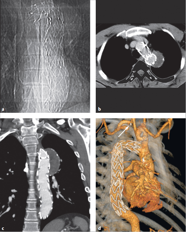
Aortic coarctation is often associated with hypoplasia of the aortic arch. It must be surgically enlarged via a median thoracotomy using a heart–lung machine and selective head perfusion, or supplied by means of a bypass from the ascending aorta to the descending aorta (▶Fig. 4.68c).
Balloon angioplasty has become the treatment of choice for older children, adolescents, and adults, particularly for short stenoses. For adolescents and adults, this is generally combined with stent placement (▶Fig. 4.71). The stenosis is often dilated gradually using balloons 2.5–3 times the diameter of the isthmus, though no larger than the diameter of the aorta near the diaphragm or of the pre-stenotic aortic arch. 72

Postoperative and Postinterventional Issues
This surgery carries the risk of damaging the phrenic and recurrent nerves, resulting in unilateral paralysis of the diaphragm or vocal cords. In rare cases, the thoracic duct can also be damaged, leading to subsequent chylothorax. In even rarer cases, paraplegia of the lower extremities (also known as post-coartectomy syndrome) can occur. The restenosis rate after surgery is high, namely 5–10% in older children (▶Fig. 4.66). For cases of critical aortic coarctation or aortic arch hypoplasia (▶Fig. 4.68c), however, this rate is substantially higher. 73 , 74
Catheter interventions carry the risk of damage near the arterial vascular access (bleeding, thrombosis, aneurysms). Dilatation can also cause the aorta to rupture or aneurysms or dissections to form, though only in rare cases. If a stent is placed, there is a risk of stent fracture, stent dislocation, or restenosis caused by neointima formation near the stent.
Over the long term, this can lead to restenosis, aneurysm formation, or persistent arterial hypertonia in a not inconsequential number of patients. Patients with associated bicuspid aortic valve have an elevated risk of restenosis or ectasia of the ascending aorta, and patients have an elevated risk of developing aneurysms near the surgical site after aortic arch or patch aortoplasty, particularly if foreign materials were used (▶Fig. 4.68). 75 , 76
Note
Arterial hypertonia is often still present immediately after aortic coarctation treatment and persists in up to 50% of patients without evidence of relevant residual stenosis or restenosis.
The lack of elasticity in the aortic arch and associated hemodynamic changes are believed to be the cause of this persistent arterial hypertonia. Thus, consistent antihypertensive treatment should be given. 77
Goals and Relative Value of Diagnostic Imaging
For infants and small children, echocardiography is the imaging method of choice due to the generally good acoustic window. In particular, this technique can be used to depict the degree of stenosis, a potentially open ductus arteriosus, left ventricular function, and associated defects. Ideally, the aortic arch is depicted via a suprasternal or jugular acoustic window (▶Fig. 4.63) when using cranial extension, or from a right parasternal view.
For older children, adolescents, adults, and especially for patients with previous surgeries, echocardiographic depiction can be significantly restricted by the limited acoustic window. In these cases, MRI and particularly contrast-enhanced MRA (including 3-D reconstruction) are the modalities of choice (▶Fig. 4.64c and d), followed by multi-slice CT (▶Fig. 4.72; also ▶Fig. 4.68b). Both of the former allow detailed depiction of the stenosis, collaterals, left ventricular function and mass, and associated defects, as well as aneurysms or restenosis in previously treated patients. Particularly after stent placement (▶Fig. 4.70 and ▶Fig. 4.71), multi-slice CT is superior to MRI if there is evidence of restenosis caused by neointima formation or stent fractures. Although performing an MRI after stent placement in the aorta is not contraindicated, and many stents (particularly nitinol ones) only generate minor artifacts, MRI quality near the stent is still limited. MRI can be used for precise quantification of an associated bicuspid aortic valve andO any stenoses it may have caused, as well as aortic valve insufficiency and ventricular function. MRI flow measurement is suited to determining the extent of collateralization of the aortic coarctation. In cases of very high-grade, subtotal stenoses, collateral flow can be significantly higher than that in the aorta immediately distal to the stenosis. This can be depicted well using 4-D flow measurement (▶Fig. 4.72). This method can also be used to estimate the relevance of a restenosis. 78 , 79 In the future, new 4-D MRI flow measurement technologies 80 could also be helpful for planning optimal surgical techniques in order to restore physiological flow, if possible (▶Fig. 4.69). Just like Doppler echocardiography, MRI also allows instantaneous pressure gradients to be estimated by determining maximum flow velocity in the stenosis by means of MRI flow measurement and the phase contrast technique, and by using the simplified Bernoulli equation. This correlates well to invasively measured pressure gradients, at least for minor-to-moderate stenoses. 78

Note
All tomographic procedures measure the diameter of the ascending aorta, the transverse and distal aortic arch, and the descending aorta distal to the stenosis. The length of the stenosis, as well as any potentially associated vascular anomalies (head and neck vessels, renal arteries) or collaterals are determined. This is decisive for treatment planning purposes. 62
Often, the thoracic X-ray in p.-a. projection depicts an aortic coarctation in adults due to the typical rib notches, shallow recesses on the inferior margins of the third–eighth dorsal ribs (▶Fig. 4.64a). Otherwise, heart size is generally normal and only enlarged in cases of critical aortic coarctation. X-rays depict signs of pulmonary obstruction. Due to this pre-stenotic enlargement of the left subclavian artery generally present near the aortic coarctation (▶Fig. 4.64, ▶Fig. 4.66, ▶Fig. 4.72) and the post-stenotic enlargement of the descending aorta, X-ray or angiographic images depict a typical left-side “notch,” the image of a double aortic knob. In principle, Doppler echocardiography and tomographic procedures are used for preoperative diagnostics. A postinterventional stent fracture, however, can also be recognized on a simple X-ray p.-a./lateral image (▶Fig. 4.70a).
An invasive cardiac catheter examination is indicated for precise quantification and invasive measurement of the pressure gradient (▶Table 4.22). Generally speaking, the decision to perform surgical or interventional treatment can occur noninvasively using Doppler echocardiography and/or MRI or multi-slice CT tomographic procedures. To that end, invasive diagnostics are usually only performed if an interventional treatment (namely, balloon angioplasty or stent placement) is also anticipated. 81 However, there are already initial case studies using MRI-guided aortic coarctation treatment with fluoroscopy as a backup. 82
▶Table 4.22 compares the relative value of imaging procedures.
Note
The MRI and multi-slice CT tomographic procedures are each class I2 indications for diagnosing a coarctation, meaning the diagnostic precision is comparable to that of other diagnostic methods. 7
4.3.3 Interrupted Aortic Arch
Definition
This rare congenital defect is characterized by a complete interruption between two segments of the aortic arch (interrupted aortic arch, IAA), which are, at most, still connected via residual connective tissue, but possess no vascular connection to one another (like in cases of aortic isthmus atresia). Unlike aortic coarctation, IAA is a rare congenital heart defect, comprising less than 0.1% of all heart defects. In theory, the aortic arch can be interrupted at any point (▶Fig. 4.73), regardless of whether a left or right arch is present. 83

Classification
The interruption is classified as one of three types based on its location from distal to proximal (▶Fig. 4.73). Frequency is indicated using the system developed by Schumacher et al.: 83
Type A: Interruption distal to the origin of all head and arm vessels (approximately 40% of cases)
Type B: Interruption between the left subclavian artery and the left carotid artery (approximately 55% of cases)
Type C: Interruption between the left carotid artery and the brachiocephalic trunk (this is mirrored for right-side aortic arch, namely, between the right carotid artery and right subclavian artery; approximately 5% of cases)
An isolated form occurs only in about 3–4% of cases, 83 , 84 most of which are type A. Otherwise, a number of primarily left-side defects with concurrent PDA and VSD, bicuspid aortic valve and more complex defects such as TGA, truncus arteriosus, or even HLHS have been described.
Hemodynamics and Clinical Issues
“Ductal-dependent” systemic circulation is common to all types. In these cases, antegrade perfusion occurs via the descending aorta and thus all circulation in the lower body occurs solely via a PDA. Depending on the location of the interruption, the distal head and arm vessels may be supplied via the PDA and retrograde perfusion via the distal arch segment. Due to the left–right shunt through the PDA, affected children begin to display clinical symptoms caused by a difference in transcutaneously measured oxygen saturation (with a lower value in the lower extremities and a normal value in the right hand), provided that these measurements are taken during screenings. Physiologic closure of the PDA is fatal to these patients, and correlates to additional clinical symptoms. Nevertheless, an IAA can also first manifest itself clinically in adulthood. 84 , 85
Treatment
Like in cases of HLHS, a prostaglandin E infusion can be used to enlarge the PDA or hold it open, though this is a temporary, emergency treatment. If possible, surgical treatment should occur as a single intervention in newborns (namely an end-to-end anastomosis, subclavian artery angioplasty, or prosthetic interposition), based on the concurrent defects and the length and localization of the interruption. As mentioned, the mortality rate remains high. 83
Diagnostics and the Role of Imaging Procedures
Though fetal echocardiography can be used to diagnose this condition prenatally, the condition is not apparent in many patients until after birth, not infrequently after the patient has entered cardiogenic shock. In less severe cases with only partial ductal closure, symptoms may closely resemble those of a preductal aortic coarctation. In theory, it is also possible to use MRI for prenatal diagnosis. 86
Thoracic X-rays often depict pronounced cardiomegaly caused by the pronounced right–left shunt. A diagnosis cannot, however, be determined using thoracic X-rays.
Final diagnosis is usually determined solely using TTE. The interruption can often be depicted clearly from a suprasternal view. In mild cases, a tomographic method is preferable to a cardiac catheter examination. Despite the radiation exposure, 84 , 85 , 87 CT is preferable to MRI in critically ill patients due to the speed of the former method (▶Fig. 4.74). For hemodynamically stable children, MRI should be used in order to reduce radiation exposure.

In addition to diagnosing and classifying the IAA, it is beneficial to determine the course of the interruption or length of atresia, as well as its spatial relationship to airways (trachea and main bronchus) and to the esophagus prior to surgery. The often-variable origin of the left subclavian artery is important for preoperative planning. 83
Postoperative management must include not just an assessment of cardiac function, but must also rule out or quantify any restenoses and assess their hemodynamic significance. If a larger distance must be bridged surgically (and the distal arch pulled far to the front), this can lead to bronchial compression. Thus, if clinical symptoms include airway obstruction, bronchial compression must be ruled out definitively.
The preoperative and postoperative value of the various imaging procedures depends on the concurrent illnesses paramount to the aortic coarctation (▶Table 4.22). In the future, 4-D MRI will likely also provide additional insights into altered preoperative and postoperative hemodynamic situations in cases of IAA. 88
4.4 Complex Defects
4.4.1 Transposition of the Great Arteries
Definition
In cases of TGA, a discordant ventriculoarterial connection is present, in which the outflow tracts of the right and left ventricles run parallel to one another (▶Fig. 4.75) rather than crossing (as occurs in normal anatomy). 83 , 89 – 91 Thus, the aorta originates partially or fully from the morphologic right ventricle, and the pulmonary artery, from the morphologic left ventricle, respectively.

In the case of a normal atrioventricular connection between the right atrium and the morphologic right ventricle, a developmental disorder of the embryonic conotruncus is present. These cases are described as complete transposition of the great arteries with intact interventricular septum (TGA IVS—often simplified to D-TGA), because the RVOT and thus also the ascending aorta are displaced to the right (“D” stands for “dextro-,” ▶Fig. 4.75).
Ventricular inversion is present if an anomalous atrioventricular connection between the morphologic right ventricle and morphologic left atrium also occurs. The TGA is then considered “congenitally corrected” and is thus also known as “congenitally corrected transposition” (ccTGA, colloquially often also called L-TGA), 91 since, in these cases of ventricular inversion, the ascending aorta generally (in up to 85% of cases 83 ) originates left of the pulmonary artery from the left-displaced, morphologic right ventricle (“L” stands for “levo-,”; ▶Fig. 4.76 and ▶Fig. 4.77; also ▶Fig. 4.75b). However, the correct nomenclature for this congenital heart defect is ccTGA.


Note
In cases of ccTGA, the morphologic right ventricle and its tricuspid valve (▶Fig. 4.77d) are located on the left side, except for in cases of situs inversus (▶Fig. 4.78). The left-displaced aorta then originates from the morphologic right ventricle (▶Fig. 4.76a,c and ▶Fig. 4.77c,e). The morphologic right ventricle is supplied by the normal left atrium (▶Fig. 4.77a). Morphological characteristics of the right ventricle include the following:

Moderator band (▶Fig. 4.76c, ▶Fig. 4.77a, ▶Fig. 4.78b)
Subvalvular muscular conus (▶Fig. 4.75c,d, ▶Fig. 4.76b, ▶Fig. 4.77b,c and, ▶Fig. 4.78b)
Significant trabeculation (▶Fig. 4.76c, ▶Fig. 4.77a,d, f and, ▶Fig. 4.78b)
A tricuspid valve (▶Fig. 4.77d)
Related posts:
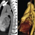
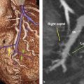

Stay updated, free articles. Join our Telegram channel

Full access? Get Clinical Tree


