Chapter 11 Alternating current (AC) flow
Chapter contents
11.1 Aim
This chapter introduces the reader to alternating current (AC) flow. The various parameters used to measure such a current will be discussed. Simple AC circuits and three-phase power supplies will be considered.
11.2 Introduction
Direct current (DC) electricity (Ch. 7) is representative of a flow of electrons in one direction only. This chapter deals with the situation where electrons flow through a circuit first in one direction and then in the other (due to the changing polarity of the ends of the circuit) – this is known as an AC flow.
11.3 Types of DC and AC
Figure 11.1 shows different types of DC and AC in graphical form – the magnitude of the current (the dependent variable) is plotted on the vertical axis against time on the horizontal axis.
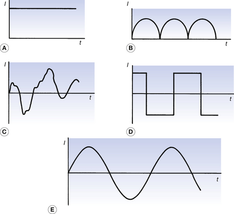
Figure 11.1A is a case where the number of electrons passing a point per second in the circuit is constant producing a horizontal straight line. This is an example of the type of DC described in Chapter 7. Figure 11.1B is a case where the electrons always move in the same direction but the number of electrons passing a point varies with time – the electrons move as a series of pulses and this is known as pulsatable or pulsating DC. In Figure 11.1C there is no discernable pattern in the flow of electrons, except to say that they flow in both directions at different times. This is an example of an irregular AC waveform. Figure 11.1D shows a situation where the number of electrons travelling in one direction is constant for a short period of time and then the same number of electrons travel in the opposite direction for the same period of time. This is an example of a square waveform. Figure 11.1E shows an example of a sinusoidal AC wave form. This is the most common AC waveform and will be discussed in detail in the remainder of the chapter.
11.4 Sinusoidal AC
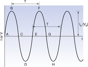
The sinusoidal AC waveform is shown in more detail in Figure 11.2, together with some of the quantities used to measure it.

For a sinusoidal current, this equation may be rewritten as:

where It is the current at a time t and Ip is the amplitude or the peak value of the current. A similar equation can be produced for the voltage.
11.4.2 Average current (or voltage)
As we can see from Figure 11.2, the average current flowing in one cycle of a sinusoidal waveform is zero, as the current flowing in one direction during the positive half-cycle has the same overall value (but of the opposite sign) during the negative half-cycle. The same conclusion applies to any number of complete cycles. A similar argument suggests that the average voltage for a sinusoidal waveform is also zero. Thus, for a sinusoidal waveform:

However, if the waveform is rectified (or made unidirectional; Ch. 28) then a value of the average current (or voltage) is obtained. The voltage waveform produced for half-wave rectification is shown in Figure 11.3A. This results in a pulsating voltage which (assuming a complete external circuit) results in a net electron flow in one direction – this allows us to consider average values of voltage and current which are not zero.
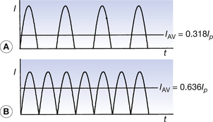
Figure 11.3 Forms of rectified sinusoidal alternating current: (A) half-wave rectification; (B) full-wave rectification.
The voltage waveform for a full-wave rectified circuit is shown on the same scale in Figure 11.3B. Again, a pulsating voltage is produced where the average value is twice that for the half-wave rectified circuit as there are twice as many peaks in unit time.
Thus, we can say for half-wave rectification:

and for full-wave rectification: