and Siddharth P. Jadhav2
(1)
Department of Radiology, University of Texas Medical Branch Pediatric Radiology, Galveston, TX, USA
(2)
The Edward B. Singleton Department of Pediatric Radiology, Texas Children’s Hospital, Houston, TX, USA
Abstract
This chapter deals with injuries of the ankle and foot. Various types of fractures and other injuries are presented. MR is discussed where it significantly adds to evaluation of these injuries.
Ankle
Normal Soft Tissues and Fat Pads of the Ankle
In the infant and child, three fat pads around the ankle usually are visualized on lateral view. The largest is the pre-Achilles fat pad, located just anterior to the Achilles tendon, but this fat pad is not utilized for the detection of joint fluid. Rather, the anterior and posterior fat pads lying against the joint capsule are the ones that are used (Fig. 11.1a).
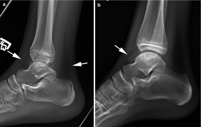
Fig. 11.1
Normal fat pads and joint fluid. (a) Note the normal anterior and posterior fat pads (arrows). (b) Note the teardrop sign (arrow) indicative of joint fluid
Detecting Fluid in the Ankle Joint
In determining whether fluid is present in the ankle joint, it is best to study the lateral view [1, 2]. On frontal view, only soft tissue swelling around the ankle is seen, but on lateral view, outward displacement of the anterior (more often) and/or posterior fat pads is seen (Fig. 11.1b). The fluid collection under the anterior fat pad has been referred to as the “teardrop” sign [2]. No joint space widening usually is seen, for the ligaments around the ankle joint are very sturdy and do not allow for much in the way of joint distraction.
Injuries of the Distal Tibia and Fibula
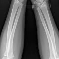
A variety of injuries can be sustained in the distal tibia and fibula, and most often these result from a combination of inversion, eversion, and rotational forces. In the young infant, cortical buckle (torus) fractures through the distal tibia and fibula are very common, especially the tibia (Fig. 11.2). In the older child, however, the more common injury is some type of Salter–Harris epiphyseal–metaphyseal fracture [3]. In the ankle, all Salter–Harris fractures types are common with the exception of the type V injury. With any of these fractures, if the fracture is overt, detection of the fracture is relatively easy (Fig. 11.3). However, in other cases, detecting the fracture is more difficult. The key to detecting these more subtle fractures lies in comparing the width of the epiphyseal plates in the injured ankle to those on the normal side and in assessing the soft tissues for evidence of swelling. Examples of Salter–Harris fractures are presented in Figs. 11.4 and 11.5.
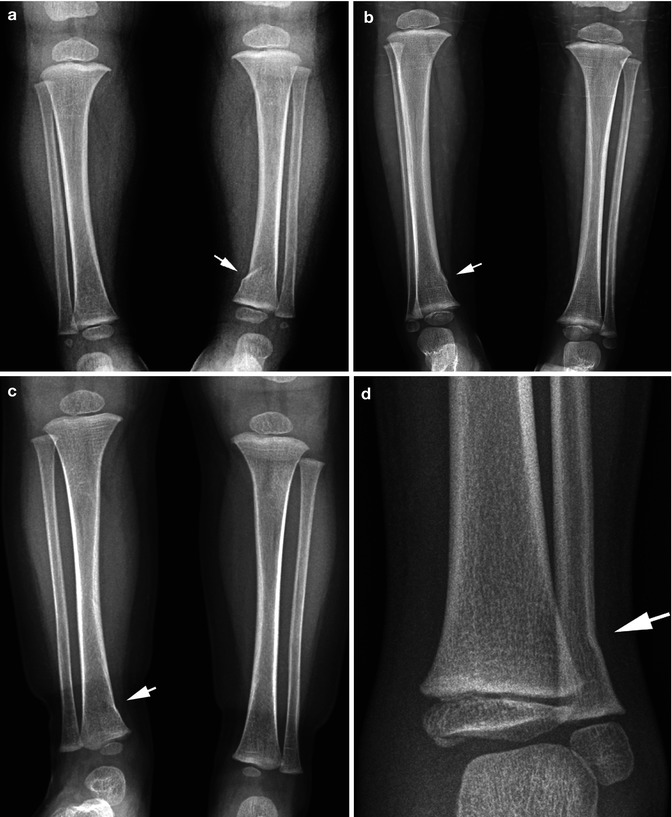
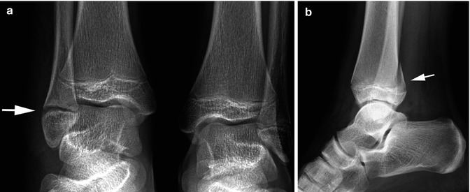
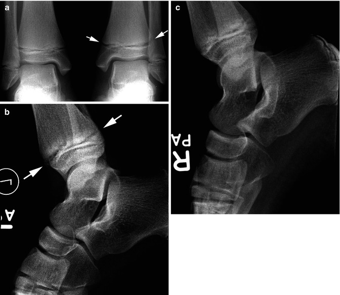
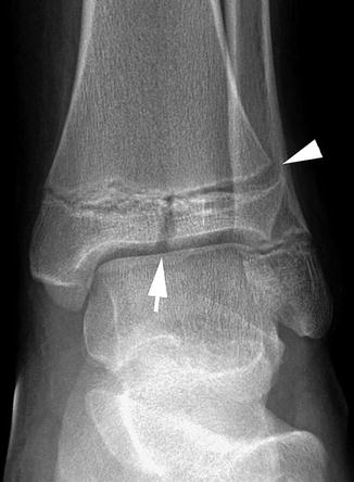
Fig. 11.2
Fractures: buckle. (a) Note the typical buckle fracture through the distal tibia (arrow). (b) A more subtle buckle fracture (arrow) through the distal tibia. (c) Another subtle angled buckle fracture (arrow) through the distal tibia. (d) Angled buckle fracture (arrow) through the distal fibula
Fig. 11.3
Salter–Harris I fracture fibula. (a) Note the widened epiphyseal plate (arrow) through the right distal fibula. Compare with the other epiphyseal plates and especially the one through the normal distal left fibula. (b) Typical Salter–Harris II through the distal tibia (arrow)
Fig. 11.4
Salter–Harris fractures: subtle findings. (a) Note widening of the epiphyseal plate (arrows) through the distal left tibia. Compare with the normal plate on the other side. The findings in the tibia are consistent with a Salter–Harris I fracture. There may be slight widening of the fibular epiphyseal plate. (b) Note the slightly widened distal tibial epiphyseal plate (arrows).The findings are subtle. (c) Normal side for comparison. Compare the normal epiphyseal plate with the slightly widened one seen in (b)
Fig. 11.5
Salter–Harris III fractures. Note the typical Salter–Harris III fracture through the distal tibia (arrow) and the widened tibial epiphyseal plate (arrowhead)
The Salter–Harris type III injury is quite common in the distal tibia (Fig. 11.5). The reason for this is that the distal tibial epiphysis fuses earlier medially than it does laterally. Consequently, with an inversion injury of the ankle, there is separation of the epiphysis laterally but not medially, and then the forces are directed downward through the epiphysis and a Salter–Harris III fracture results.
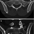
This fracture often is difficult to detect on initial inspection of the AP and lateral views. On the other hand, very often it is seen on the oblique view of the ankle (Fig. 11.6). In other cases, gross displacement of the fracture can be seen (Fig. 11.7).These fractures are the childhood equivalent of the Tillaux fracture [4] and are best assessed with CT imaging (Fig. 11.8). This is performed to define the degree of fracture fragment displacement and to determine whether internal fixation is required. The usual maximum allowable limit of the diastatic fracture is 3 mm.
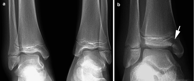
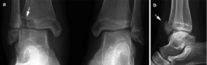
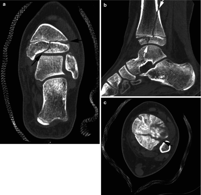
Fig. 11.6
Salter–Harris III fracture: occult on AP view. (a) Note swelling over the lateral malleolus and some suggestion of a minimal Salter–Harris I fracture through the distal fibula. The tibial epiphysis appears intact. (b) Oblique view, however, demonstrates a typical Salter–Harris III fracture (arrow)
Fig. 11.7
Salter–Harris III fracture: displaced fracture fragment. (a) Note swelling of the ankle and a Salter–Harris I injury through the distal fibula. Also note the lucent gap (arrow) through the distal lateral tibial epiphysis. (b) Lateral view demonstrates the avulsed and displaced epiphyseal fragment (arrow)
Fig. 11.8
Salter–Harris III fracture: CT findings. (a) Coronal view. Note the Salter–Harris III fracture (arrows). (b) Sagittal view. Note the Salter–Harris III fracture (lower arrow) and the associated Salter–Harris II fracture (upper arrow). (c) Axial view through epiphysis. Note the widened fracture line (arrow)
Inversion–rotation injuries of the ankle are very common, and although in most cases they result only in a sprained ankle, in other instances, Salter–Harris injuries result. In adults, the Ottawa ankle rules can, if applied, significantly reduce the number of ankle injuries requiring radiographic examination [5]. This also probably is true in children, but unfortunately there is no uniform adherence to these rules.
With inversion ankle injuries, one may only see an epiphyseal–metaphyseal separation (Salter–Harris I fracture) of the distal fibula [6, 7]. In other cases, an associated tibial Salter–Harris III fracture can be seen (see Fig. 11.6), while in still other cases, both the fibular and tibial epiphyses are involved in Salter–Harris fractures (see Fig. 11.3a). In either case, however, a more serious associated fracture through the medial malleolus of the tibial can be seen (Fig. 11.9a). In still other cases, one may encounter only a small cortical avulsion off of the distal fibula (Fig. 11.9b, c). These latter fractures must be differentiated from normal accessory ossicles occurring in this area (see Fig. 11.25).
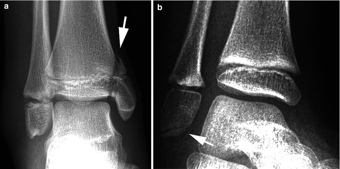
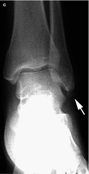
Fig. 11.9
Eversion ankle injuries. (a) Note the Salter–Harris IV fracture through the medial malleolus (arrow). There also is a Salter–Harris I fracture through the distal fibula. Marked soft tissue swelling is seen over the lateral malleolus. (b) Thin avulsed sliver of bone (arrow) off the distal fibular epiphysis. (c) In this patient, a small avulsed ossicle (arrow) is seen off of the distal fibula
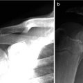
With eversion injuries, the ankle mortise often is seriously disturbed, and a wide range of relatively readily detectable injuries can be encountered (Fig. 11.10a). In other cases, only a small avulsion fracture off of the medial condyle is present (Fig. 11.10b). So-called posterior malleolar fractures actually are Salter–Harris type II epiphyseal–metaphyseal fractures, and many times the fracture is visible only on the lateral view (see Figs. 11.3b and 11.8b). This fracture is usually part of a Salter–Harris III or IV fracture and often referred to as a triradiated fracture. It is best assessed with CT scanning.
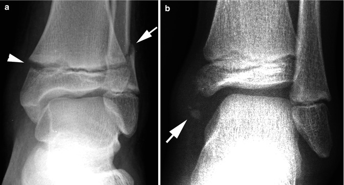
Fig. 11.10
Eversion ankle injury. (a) First note the widened tibial epiphyseal plate (arrowhead) and then the oblique fracture through the distal fibula (arrow). (b) In this patient, there is an avulsion fracture of the medial condyle (arrow). Significant edema supports the diagnosis
Injuries of the Tarsal Bones
Fractures and dislocations of the tarsal bones are generally less common in childhood than in adulthood. This is especially true in the infant and young child. In the older child, one can encounter fractures of the navicular and talus and occasionally of the other tarsal bones. Talar fractures are probably more common than the other fractures. These fractures tend to occur through the neck of the talus and there often is rotation/dislocation of the distal fracture fragment (Fig. 11.11), and subsequent aseptic necrosis is a known complication. The navicular bone also can be fractured, but very often it undergoes a stress/compression fracture which results in increased density (compressed trabeculae) of the navicular bone (Fig. 11.12). Less commonly they can occur through the talus. Fractures of the other tarsal bones are not rare but not common. Perhaps the cuneiform is one of the more involved bones (Fig. 11.13).
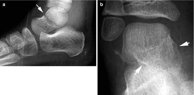
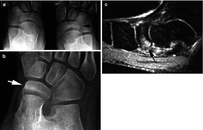
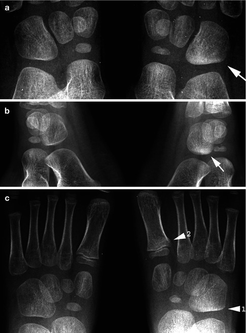
Fig. 11.11
Talar fracture. (a) Note the fracture (arrow) through the neck of the talus. The two bony fragments are of different density because there is rotation of the distal fragment. (b) Note the position of the distal fragment (arrows) consistent with rotation
Fig. 11.12
Navicular compression fracture. (a) Note increased density (arrow) of part of the navicular bone on the right. (b) Oblique view confirms the increased density (arrow). (c) Another patient. MR STIR sagittal view demonstrates increased signal (arrow) in the navicular bone consistent with a compression fracture
Fig. 11.13
Compression–impaction fracture cuboid bone. (a) Note the increased density over the lower part of the right cuboid bone (arrow). The cuboid bone also is a little shorter and squarer than the one on the left, all consistent with a compression injury. (b) Oblique view confirms the area of increased density (arrow). (c) In this patient, both types of bunk bed fractures are present. First note the area of increased density in the cuboid bone of the right (1). Then note the subtle buckle fracture through the base of the first metatarsal (2)
Impaction cuboid fractures are more common than generally appreciated and tend to occur in younger children and infants. They can be considered as part of the expanded toddler fracture concept [8–11] for these patients frequently present with limping; the cause of which remains unclear until the fracture is detected. As with all toddler fractures, diagnosis is a matter of knowing what to look for and where to look for it. In this regard, with cuboid fractures, the most significant finding is an increase in density and, in many cases, decrease in size of the cuboid bone (Fig. 11.14). At first, increased density is due to trabecular compression, but eventually, it is due to a combination of trabecular compression and new bone healing. Plain films usually suffice, but nuclear scintigraphy and MR imaging also can detect these injuries.
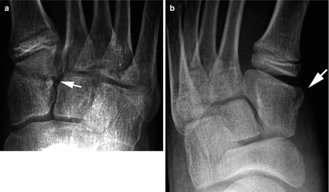
Fig. 11.14
Cuneiform fractures. (a) Note the avulsion-type fracture (arrow) through the cuneiform bone. (b) Another avulsion fracture (arrow)
Fractures of the calcaneus usually result from patients jumping or falling on their heels, and many are subtle or occult [12–16]. In some cases, a clear-cut fracture line is visualized, but otherwise one must look for indirect findings such as soft tissue swelling, loss of Bohler’s angle, decreased height of the calcaneus, and increased density (impaction) of the calcaneus (Fig. 11.15). Often these fractures are finally best seen on tangential views of the calcaneus.
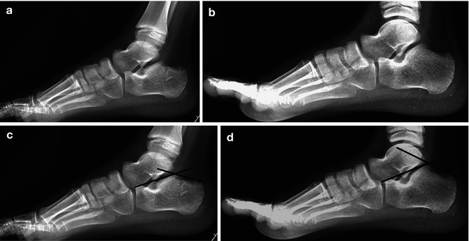
Fig. 11.15
Calcaneal fracture. (a) Note the slightly irregular contour of the calcaneus, a buckle fracture over the posterior inferior surface, and some increase in density. (b) Normal side for comparison. Note the normal appearance of the calcaneus with clearly visible trabeculae. These are not seen as clearly in Fig. 11.5a. (c) Bohler’s angle is reduced on the affected side. (d) Bohler’s angle is normal on the normal side
Other fractures which can involve the calcaneus include fractures of the anterior process (Fig. 11.16) and simple buckle fractures (Fig. 11.17a). In addition, the apophysis of the calcaneus can be fractured (Fig. 11.17b, c). It is important, however, to not misinterpret normal irregularity of the normally sclerotic calcaneal apophysis for a fracture (see Fig. 11.26).
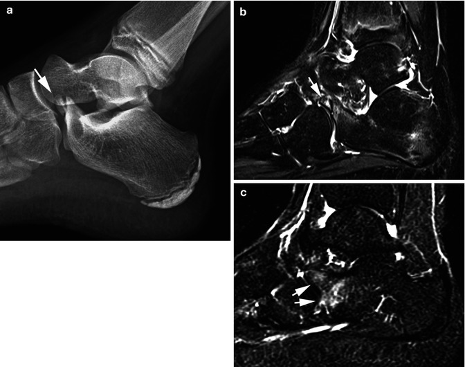
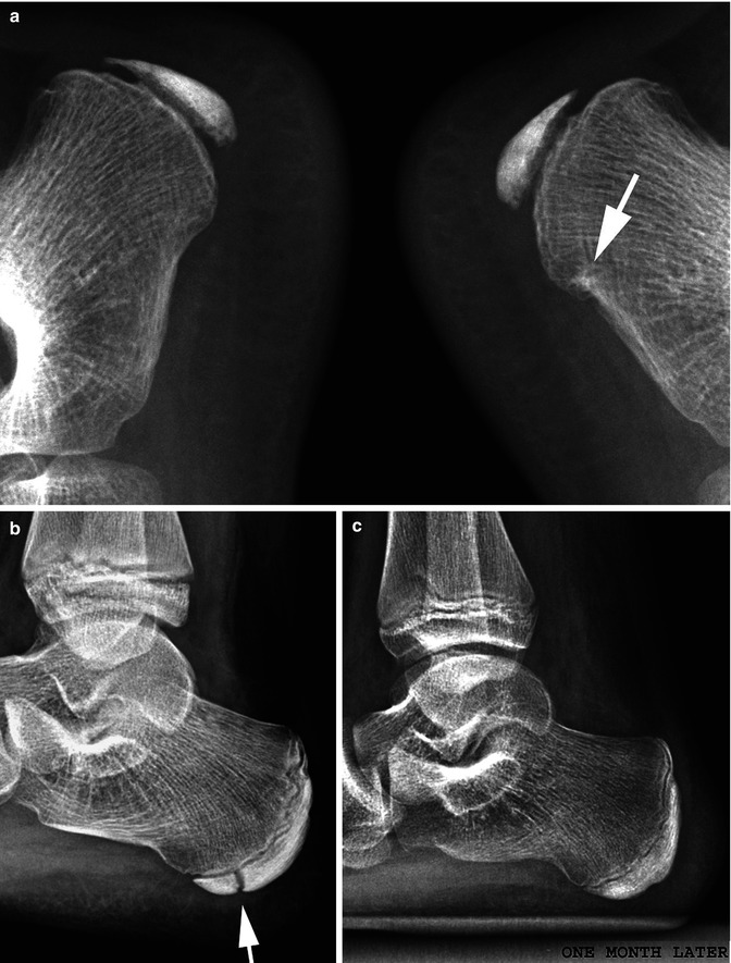
Fig. 11.16
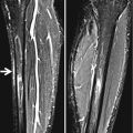
Calcaneal anterior process fracture. (a) Note the avulsion fracture of the anterior process of the calcaneus (arrow). (b) Sagittal STIR MR image demonstrates the avulsed fracture fragment with internal marrow increased signal (arrow). There also is some increased signal in the adjacent calcaneus. (c) Another patient. The plain radiographs were normal in this patient. However, in a STIR MR study, sagittal plane demonstrated increased signal in the anterior process and the adjacent calcaneus (arrows)
Fig. 11.17
Other calcaneal fractures. (a) Note the subtle buckle fracture (arrow) of the right calcaneus. (b) Fracture of the calcaneal apophysis (arrow). Note that the fracture edges are very sharp. (c) One month later, healing has occurred and the fracture is no longer visible. It is important to differentiate these fractures from normal fracture-like findings in the normal calcaneal apophysis. With the latter, the edges of the lucency are not sharp (see Fig. 11.26)
Small avulsion fractures of the various tarsal bones and other bones around the ankle also can be encountered. These are more common than generally appreciated, and although they may be visible on standard views, very often oblique views first bring these fractures to light (Fig. 11.18). Indeed, in some cases, visualization of these fractures is strictly fortuitous, and all of them must be differentiated from normal accessory ossification centers of the various bones around the ankle (see Fig. 11.25).
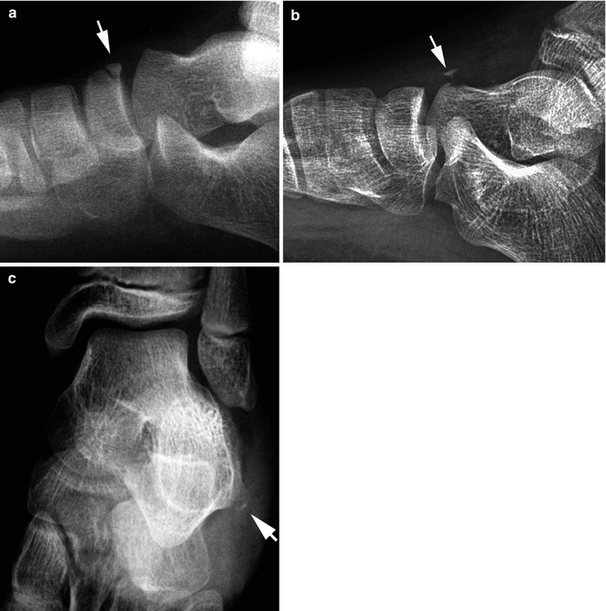
Fig. 11.18
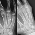
Avulsion fractures of the ankle. (a) Note the subacute avulsion fracture (arrow) off of the tarsal navicular bone. (b) Acute avulsion fracture (arrow) off of the talus. Note adjacent soft tissue swelling. (c) Acute avulsion fracture (arrow) off of the calcaneus
Tarsal bones are often the site of stress reactions and fractures. This may be a fatigue fracture (Fig. 11.19) or an insufficiency fracture from weight bearing after bone resorption secondary to immobilization.
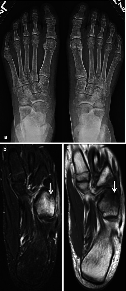
Fig. 11.19
Stress fracture. (a) AP radiograph of the feet in a gymnast complaining of right lateral foot pain. No abnormality was seen. (b) Coronal STIR image of the foot shows high-signal edema in the cuboid with a hypointense fracture line distally (arrow). (c) The fracture (arrow) is confirmed on the T1-weighted image
Sprained Ankle
Unlike the sprained wrist, a sprained ankle most often turns out to be nothing more than a sprained ankle. Of course, this is not to say that fractures never occur but only to point out that the high incidence of underlying fracture that accompanies wrist sprains is not present with ankle sprains. Another important aspect of a sprained ankle resulting from an inversion injury is that very often there is an associated fracture of the base of the fifth metatarsal. The peroneus brevis muscle inserts into this bone, and with inversion injuries, an avulsion fracture frequently occurs. This fracture usually is initially overlooked clinically but almost always is detectable roentgenographically (see Fig. 11.33).
Related posts:

Stay updated, free articles. Join our Telegram channel

Full access? Get Clinical Tree


