Fig. 24.1
Two-dimensional transthoracic echocardiogram using a parasternal long-axis view of the aortic root demonstrating a thickened, bright aortic valve. The aortic dimensions shown here include diameter of the left ventricular outflow tract (yellow line A), diameter of the aortic annulus (yellow line B), diameter of the aortic sinus (yellow line C), diameter of the aortic sinotubular junction (yellow line D), and sinotubular height (yellow line E)
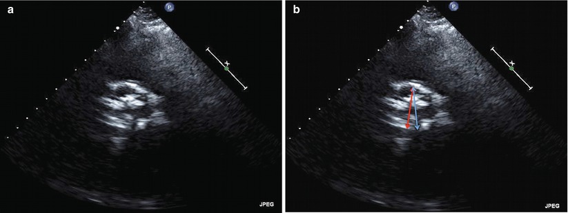
Fig. 24.2
Two-dimensional transthoracic echocardiogram from the parasternal short-axis window of the aortic root demonstrating maximal valve opening in systole. (a) Although there is heavy calcification, TTE is usually adequate to identify the number of aortic cusps, three in this image. (b) The annular distance as measured by transthoracic echocardiography does not correspond to the maximum diameter of the annulus. In this short-axis image, the red double arrow corresponds to the annular dimension as measured from the parasternal long-axis view. The full diameter of the outflow tract (blue double arrow) is shown in this short-axis image
TEE
Transesophageal echocardiography (TEE) is useful for technically complicated or challenging cases, when annular size is uncertain or close to established cutoffs and for determining the number of cusps when transthoracic imaging is equivocal [3, 9, 15]. A mid-esophageal long-axis image at 120–140° traditionally provides adequate views of the LVOT and annulus in a sagittal plane similar to TTE (Fig. 24.3). Single-plane short-axis views at 35–60° can also demonstrate the shape of the annulus but should not be used in isolation due to limitations in identifying the identical plane obtained from long-axis views. Employing biplane imaging to obtain a short-axis image, however, augments the usefulness of this view to demonstrate the elliptical shape of the annulus (Fig. 24.4a–c). TEE-based annular measurements generally correlate with TTE (r = 0.89) although TTE-based measurements are usually larger with mean difference of 0.22 mm and absolute difference between TEE and TTE of 0.6 ± 0.8 mm [16]. TEE measurements demonstrate higher intra- and interobserver concordance than TTE and computed tomography and have been shown to alter prosthesis selection in 16 % of cases compared to dual-source computed tomography [17, 18].
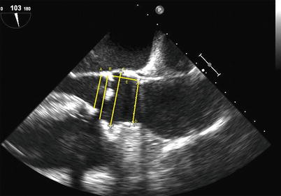
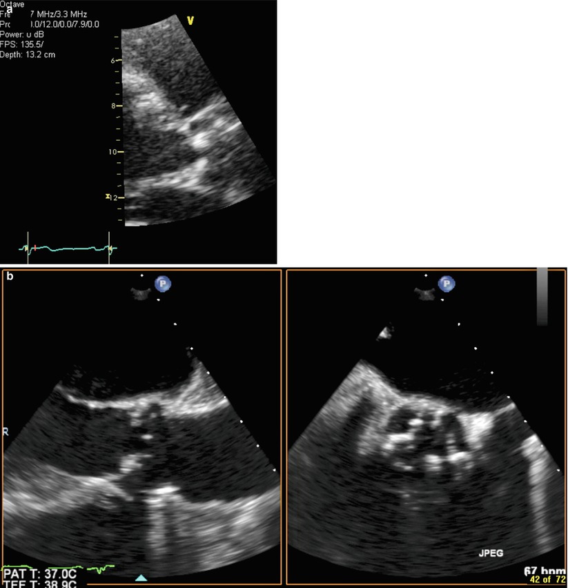
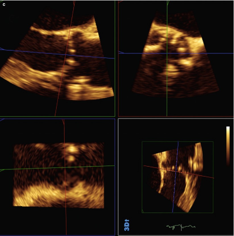
Fig. 24.3
Two-dimensional transesophageal echocardiogram showing a long-axis view of the aortic root demonstrating a thickened and bright aortic valve. In this view, the following aortic dimensions are shown: diameter of the left ventricular outflow tract (yellow line A), diameter of the aortic annulus (yellow line B), diameter of the aortic sinuses (yellow line C), diameter of the aortic sinotubular junction (yellow line D), and sinotubular height (yellow line E). Calcification of the aortic annulus may make measurement difficult
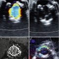
Fig. 24.4
Use of biplane imaging to view the true elliptical shape of the aortic annulus. (a) Two-dimensional transthoracic echocardiogram of left parasternal long-axis view of aortic root showing calcified aortic leaflets. (b) Two-dimensional transesophageal echocardiogram biplane images showing the aortic root in long axis and short axis. (c) Three-dimensional transesophageal echocardiogram full-volume data set cropped to show the aortic root in the same patient from (a) and (b)
Comparison to Other Noninvasive Imaging Modalities
There is no gold standard for noninvasive assessment of aortic annulus dimensions. Whether it is TTE, TEE, or another noninvasive method, the ultimate decision will fall to the operator depending on local expertise and availability. Each technique has its advantages and disadvantages [4]. It is important, however, to recognize the unique characteristics of echocardiography. The sagittal plane measurement by TTE and TEE usually approximates the minor axis of the elliptically shaped annulus as measured by multi-detector computed tomography (MDCT) scanning. The difference between MDCT and TTE (1.22 ± 1.3 mm) or TEE (1.52 ± 1.1 mm) is larger than the difference between TTE and TEE [16]. In addition, traditional TTE or TEE measurement of the annulus uses long-axis images of the aorta in which the cusp opening is centered in the aorta; however, this view does not bisect the aorta at its largest dimension but rather images a plane just lateral to the maximum dimension which may cause significant underestimation of the true maximal annular diameter [2]. This is the most likely cause of undersizing of the annulus by echocardiographic measurement. Preprocedural MDCT-based measurements of annular diameter and post-procedural comparisons of THV area to annulus area predict paravalvular aortic regurgitation slightly better than TEE annular diameter (area under the curve: 0.81 compared to 0.70, respectively) [19]. Newer MDCT-based approaches which employ three-dimensionally derived cross-sectional measurements of the aortic annulus affect device sizing and patient selection and reduces paravalvular aortic regurgitation for the Edwards SAPIEN™ THV compared to traditional two-dimensional TEE [20]. This underscores the added value of routinely employing three-dimensional techniques for aortic annulus sizing such as by MDCT, cardiac magnetic resonance imaging (CMR) [21], or three-dimensional TEE [18, 22].
Echocardiography, however, has limitations in some patients being considered for TAVR. Most notable is the acoustic shadowing that can obscure interpretation of the annular complex due to heavily calcified aortic leaflets or root. With TEE, mitral annular calcification can also cause acoustic shadowing over the LVOT. In addition, with two-dimensional imaging, the imaging field is in a single plane that can lead to different measurements compared to three-dimensional real-time imaging and multiplanar reconstruction which allows complete morphologic analysis [23].
Echocardiographic Assessment of the Aortic Leaflets
The major implications of aortic leaflet morphology for TAVR are related to the number of cusps present, the degree of leaflet calcification, and the height of the leaflets with respect to the coronary ostia. The latter is addressed in a separate section. Bicuspid aortic valves are considered a contraindication for TAVR due to concerns of poor seating, asymmetrical stent expansion, and/or paravalvular aortic regurgitation due to severe distortion of the native valve leaflets [10, 11]. Although there are now numerous reports of successful TAVR procedures in patients with congenitally bicuspid aortic valves [24–28], incomplete deployment may lead to aortic regurgitation or impairment of valvular function [29].
Echocardiography can evaluate the extent, location, and distribution of AoV calcification and provide important information helpful for the success of TAVR. Severe, asymmetric calcification of the AoV leading to asymmetry of leaflet excursion may also result in incomplete expansion of the THV, limited orifice size and paravalvular regurgitation. One grading system used for surgical AVR which discriminates calcium being confined to leaflet tips (mild), calcium extending from the leaflet tips to the leaflet bases (moderate), and bulky calcification that extended from tip to base in all three leaflets (severe) has shown modest correlation with the actual weight of the excised native valve (Box 24.1) [30]. Bulky AoV calcification is a risk factor for left main coronary artery occlusion during THV deployment, and in rare cases, with creation of a membranous septal defect due to inferior displacement of extensive annular or basal leaflet calcifications during stent expansion [31]. Valvular calcification poses a risk with either the SAPIEN™ or CoreValve® THV; however, positioning of the CoreValve® is more independent of valvular calcification owing to its constrained waist and larger length.
Box 24.1 Echocardiographic Grading of Aortic Valve Calcium
Aortic Valve Calcification Grading System (adapted from that used for surgical aortic valve replacement) | |
Mild | Calcium being confined to leaflet tips |
Moderate | Calcium extending from the leaflet tips to the leaflet bases |
Severe | Bulky calcification that extended from tip to base in all three leaflets |
TTE
TTE is usually adequate to identify the number of aortic cusps and to quantify severity, location, and symmetry of calcification (see Fig. 24.2a). A long-axis parasternal view of the LVOT and aorta is used to identify the severity of calcification and overall valve mobility. While the right coronary cusp and left or noncoronary commissure are visible in the traditional long-axis view, short-axis views of the aortic valve from the parasternal or subcostal window are also often necessary to identify the exact number of cusps, location of calcification, and commissural fusion, if present.
TEE
It must be noted that significant AoV calcification may limit further analysis by TTE due to acoustic shadowing. If this is the case, TEE may be helpful [32]. A mid-esophageal short-axis image at 35–60° or biplane imaging from the long-axis image traditionally provides adequate views of the aortic cusps and commissures. In addition to classifying calcification, valve opening (e.g., concentric, eccentric) should also be described. The role of three-dimensional transesophageal echocardiography in the preprocedural assessment is still evolving but has mostly involved providing an accurate depiction of the annulus and measurement of the annular-coronary ostial distance and, less often, providing an assessment of the aortic cusps when TTE is indeterminate. Limitations related to acoustic shadowing by calcium deposits also apply to imaging of the aortic leaflets especially if the calcification extends into the annulus, the sinuses of Valsalva, and mitral annulus. Image acquisition from deep gastric views allows the operator to avoid shadowing from calcification in the aortic annulus and ascending aorta but does not usually overcome shadowing from calcification of the mitral valve apparatus. Resolution is also decreased compared to esophageal views because of the valve’s greater distance from the transducer.
Comparison to Other Noninvasive Imaging Modalities
There are few published direct comparisons between various noninvasive multimodality imaging techniques for assessment of the aortic leaflets themselves. However, given that calcification and morphology are major aspects of this component of the aortic annular complex, there are strengths and limitations that deserve consideration. Severe and bulky calcification of the aortic leaflets and annulus may render echocardiography and CMR unreliable, while less severe calcification may not pose as much limitation [33]. CMR delineates calcium as a low signal permitting visualization of the valve but may limit the ability to perform precise measurements [34]. MDCT, on the other hand, allows imaging of the exact location and quantification of calcification that may aid in prognosis of patients with aortic stenosis (AS) and planning for TAVR [35, 36]. The choice of modality must also take into consideration comorbidities such as renal dysfunction, dye allergy, arrhythmias, and pulmonary disease as these may limit the use of potentially nephrotoxic intravenous contrast, ECG gating, and breath holds for MDCT and CMR, respectively.
Echocardiographic Assessment of the Coronary Ostia
Coronary artery compromise is an important but fortunately infrequent complication of TAVR occurring in <1 % of patients in clinical trials and single-center reports [37, 38]. The SAPIEN™ Aortic Bioprosthesis European Outcome (SOURCE) Registry reported a 0.6 % incidence of coronary obstruction over 30 days in their post-marketing registry [39]. The possible mechanisms for coronary ostial obstruction during TAVR have been described and include (1) impingement of the coronary ostia by the THV support structure; (2) inappropriately high positioning of the sealing cuff of the THV; (3) embolization of atheroma, calcium, thrombus, air, or vegetation; (4) an oversized THV; (5) aortic root dissection; and (6) displacement of the native and bulky aortic leaflets towards the coronary ostia (Box 24.2) [37, 40–42]. Webb described risk factors for coronary ostial obstruction which include a low-lying coronary ostium <10–12 mm from the basal leaflet insertion to the coronary ostium, bulky calcification of native leaflets, and a narrow aortic root [42]. These risk factors have been present in many of the reported cases of coronary ostial obstruction during TAVR [41, 43] although no definite criteria exist to exclude patients on the basis of risk for coronary obstruction.
The normal adult aortic cusps vary in height even in apparently tricuspid valves without congenital malformation. Vollebergh et al. described the natural variation in leaflet height with right, noncoronary, and left coronary leaflets measuring on average 14.1, 14.1, and 14.2 mm, respectively. In adults with calcific AS, the average right, noncoronary, and left coronary leaflet heights are slightly smaller: 13.9, 13.6, and 14.0 mm, respectively [44]. Minimum recommended annular-ostial heights for the 23 and 26 mm SAPIEN™ THVs are >10 and >11 mm, respectively [4], although some suggest a more cautious approach using >14 mm as a general guideline for a safe annular-ostial distance [31]. The annular-ostial height is not relevant for the CoreValve® THV because of its unique structure and constrained waist which sits within the SoV to avoid “jailing” the coronary ostia [3]. For the self-expanding valve, however, the height of the SoV is an important consideration, with a preferred SoV height of >15 mm. SoV heights of <10 mm are generally considered so low as to preclude successful THV implantation [45].
Box 24.2 Possible Mechanisms for Coronary Ostial Obstruction During TAVR
1. Impingement of the coronary ostia by the THV support structure |
2. Inappropriately high positioning of the sealing cuff of the THV |
3. Embolization of atheroma, calcium, thrombus, air or vegetation |
4. Oversized THV |
5. Aortic root dissection |
6. Displacement of the native and bulky aortic leaflets towards the coronary ostia |
TTE/TEE
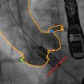
On the basis of the likely mechanisms of coronary ostial obstruction and to minimize the risk, echocardiography can provide important preprocedural information. It is crucial to know the distance from the virtual basal ring (“aortic annulus”) to the ostia of the left and right coronary arteries and to compare this with the length of the cusps. TTE is inferior to TEE in this regard due to low resolution and limited views of the cusps and coronary ostia in the long axis. Two-dimensional TEE is able to define the annular-ostial distance and length of the right coronary cusp using a mid-esophageal long-axis view of the LVOT and aortic root. This is best achieved in the long-axis view of the LVOT slightly off-axis to show the right coronary ostium and proximal right coronary artery. For the left main coronary ostium, three-dimensional TEE is required as the left main ostium lies in the coronal plane that cannot be imaged using standard two-dimensional TEE imaging. By using a three-dimensional full-volume data set of the aortic root complex and multiplanar reconstruction, the left annular-ostial and cusp length can be acquired (Fig. 24.5a, b).
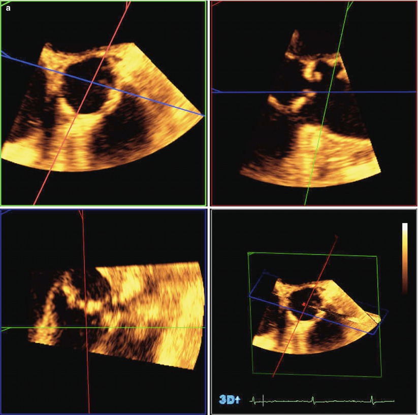
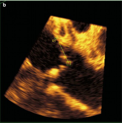
Fig. 24.5
Three-dimensional transesophageal echocardiography used to identify the relationship between the aortic valve and left coronary ostium. (a) Full-volume data set acquired by transesophageal echocardiography cropped to show the aortic root and the origin of the left coronary artery. (b) The full-volume data set from 6A has been cropped to show the origin of the left coronary artery. Yellow line D1 represents left coronary leaflet length, and Green line D2 represents distance from leaflet insertion to left coronary artery ostium
Comparison to Other Noninvasive Imaging Modalities
Aortic cusp length and annular-ostial height can be measured noninvasively using echocardiography, CMR, and MDCT [46]. Severe calcification may cause acoustic shadowing with TTE. Moreover, severe calcification can cause a signal void with CMR, leaving MDCT scanning or TEE as noninvasive imaging methods of choice for determining annular-ostial height and leaflet length. There have been no trials comparing various noninvasive imaging modalities in assessing the relationship of measures of annular-ostial height with clinical outcomes.
Echocardiographic Assessment of the Sinotubular Junction and Proximal Aorta
The sinotubular junction (STJ) describes the upper most ring of the aortic root complex representing the interface between the aortic root and the tubular ascending aorta and plays an important role in maintaining competence of implanted prosthetic valves [47]. Echocardiographic studies demonstrate the dynamic nature of the aortic root during the cardiac cycle with the STJ width increasing by 3.4 ± 1.9 mm from diastole to systole [48]. Echocardiographic and ex vivo studies have also demonstrated that the STJ and ascending aorta are usually larger in patients with calcific AS compared to patients with normally functioning valves with a mean difference of 1.3 mm [2, 49]. For TAVR, STJ width and the presence and degree of calcification appear to be critical and may be related to the incidence of patient-prosthesis mismatch (PPM) [50, 51]. Small and heavily calcified STJs may predispose patients to balloon migration, THV embolization, or aortic root rupture during implantation of the THV and is associated with more severe atherosclerotic aortic arch disease [3, 52–54]. Although consideration of the STJ width and degree of calcification appear critical for correct and lower-risk positioning, quantitative data on the impact of the STJ and tubular aorta size and morphology on TAVR outcomes are limited [55].
TTE
Two-dimensional TTE images should be used to visualize the aortic root in different views in varying intercostal spaces and at different distances from the left sternal border. Right parasternal views, with the patient in a right lateral decubitus position, can also be useful to focus on the root including the STJ. In the long-axis view from parasternal views (i.e., corresponding to the sagittal plane by other noninvasive modalities), the STJ is measured in a similar manner to the aortic annulus and SoV from tissue-blood interface to blood-tissue interface (see Fig. 24.1). Significant calcification may limit accurate measurement by TTE.
TEE
The thoracic aorta is generally better imaged using TEE as it lies in the near field of the transducer. The STJ can be seen in the mid-esophageal long-axis view between 120 and 140° or slightly higher in the esophagus depending on the orientation of the heart and aorta.
Comparison to Other Noninvasive Imaging Modalities
Noninvasive imaging assessment of the STJ varies significantly depending on the modality. Two-dimensional TTE measurements of the STJ and ascending aorta are usually significantly smaller than CMR-based measurements [34]. While MDCT and CMR measurements of the STJ and ascending aorta are usually in close agreement, the agreement between TTE and either noninvasive method is poor. For the STJ, Jabbour et al. described 95 % limits of agreement for the largest measurement of −4.7 to 3.1 mm comparing CMR to MDCT, −8.4 to 7.0 mm comparing CMR to TTE, and −9.0 to 9.1 mm comparing MDCT to TTE [56]. Poor agreement between CMR and MDCT scanning with TTE was also found comparing the ascending aorta in that study; however, MDCT- and TTE-based measurements of a dilated sinotubular junction or ascending aorta (i.e., as with aortic aneurysm) are comparable [57]. TEE, while not a routine part of TAVR preprocedural assessment in all centers, provides more reliable measurements of the STJ and tubular aorta than TTE [58]. Little data exists with direct comparisons between MDCT, CMR, echocardiography, and angiography for sizing of the STJ and proximal aorta in relation to clinical outcomes. Despite these shortcomings, outcomes have been excellent when echocardiographic assessments of the aortic root have been used and are comparable to those obtained using MDCT scanning [16]. Systematic comparisons of the accuracy and TAVR-related clinical implications of different multimodality techniques measuring the STJ and ascending aorta are needed.
Echocardiographic Assessment of Concomitant Cardiac and Aortic Root Pathology
Anterior Mitral Valve Leaflet
The aortic annulus is in close proximity to the mitral valve apparatus with the majority of the noncoronary leaflet and a portion of the left coronary leaflet in fibrous continuity with the anterior mitral valve leaflet. The two interleaflet triangles abutting the noncoronary leaflet are also in fibrous continuity with the right and left fibrous trigones, the anterior mitral valve annulus (the aorto-mitral curtain), and a portion of the membranous septum. Anterior mitral valve morphology is especially important to characterize in the preprocedural phase in order to avoid unintentional impingement of the anterior leaflet with placement of the THV too low within the ventricle [52]. Moreover, dense calcification within the aorto-mitral curtain or mitral annular calcification may increase the risk of paravalvular regurgitation due to asymmetric expansion of the THV [59].
Mitral Regurgitation
Most (76 %) patients with severe AS have some degree of mitral regurgitation (MR), and moderate-to-severe MR is seen in 22–48 % of patients undergoing TAVR [10, 40, 60]. Most of these patients have organic as opposed to functional MR [61]. During implantation, the guidewire or introducer sheath may interfere with the mitral subvalvular apparatus and cause or worsen the degree of MR. Worsening MR is included in the differential diagnosis of acute hemodynamic instability during implantation, and as such the operator should be aware of any baseline mitral insufficiency. Therefore, determining the presence, nature, and degree of MR should also be a routine aspect of the TAVR preprocedural assessment. This is usually adequately achieved with two-dimensional transthoracic echocardiography imaging of the left atrium, mitral valve, left ventricle, and pulmonary veins using two-dimensional, color, and spectral Doppler in standard manner to characterize MR [62]. TEE with biplane or full-volume three-dimensional image acquisition may be particularly helpful intraprocedurally to identify the situation when the guidewire is caught within the mitral subvalvular apparatus.
Septal Thickness and Ventricular Thrombus
Both self-expandable and balloon-expandable THVs extend their lower edge into the LVOT. Abnormalities within this region should be identified during the preprocedural assessment in order for the operator to be able to anticipate and take steps to minimize complications (Fig. 24.6). A marked upper septal bulge, for example, protruding into the LVOT, may create a significant challenge to the proper seating of the THV and may risk repositioning after cessation of the pacing runs [4]. A prominent septal bulge has also been associated with atrioventricular (AV) block and need for pacemaker implantation post-TAVR [63, 64]. Hemodynamically significant LVOT obstruction due to septal hypertrophy is a contraindication to TAVR; however, there are reports of successful implantations performed with modifications of the THV for such patients [65].
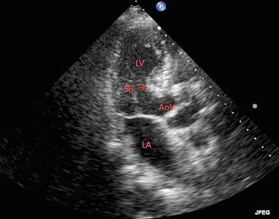
Fig. 24.6
 Transcatheter Aortic Valve Replacement: Current Evidence from Large Multicenter Registries
 Positron Emission Tomography Evaluation of Aortic Stenosis
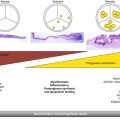 Pathologic Findings in Aortic Stenosis
 Fusion Imaging for TAVR
 Aortoiliofemoral Assessment: MDCT
 Valve-in-Valve for Transcatheter Aortic Valve Replacement: Do Imaging Requirements Change?


Two-dimensional transthoracic echocardiogram in an apical long-axis view of the left ventricle demonstrating a prominent septal bulge in the left ventricular outflow tract. LV left ventricle, LA left atrium, AoV aortic valve, SB septal bulge
Related posts:
Transcatheter Aortic Valve Replacement: Current Evidence from Large Multicenter Registries
Positron Emission Tomography Evaluation of Aortic Stenosis
Pathologic Findings in Aortic Stenosis
Fusion Imaging for TAVR
Aortoiliofemoral Assessment: MDCT
Valve-in-Valve for Transcatheter Aortic Valve Replacement: Do Imaging Requirements Change?
Stay updated, free articles. Join our Telegram channel
Full access? Get Clinical Tree
