1 Basic Principles Sound waves are mechanical waves that require a medium through which to propagate. Sound cannot travel through a vacuum. Different materials have different acoustic properties and therefore vary in their ability to transmit sound waves and reflect them at interfaces. The human ear is unable to hear sounds at frequencies higher than approximately 20,000 Hz (20 kHz). Frequencies beyond this range are known as ultrasound. Diagnostic ultrasound instruments generally operate at frequencies of 3–10 million Hz (3–10 MHz). High frequencies have shorter wavelengths, providing better spatial resolution and visualization of small tissue structures. To understand how images are produced with ultrasound, it is necessary to know something about the physics and technology of ultrasound. The most important basic concepts in ultrasound physics involve sound waves, the speed of sound, and acoustic impedance. The following formula is used to calculate wavelength, λ: λ = c/f, where c is the propagation velocity of sound in m/sec and f is the frequency or number of complete cycles in a unit of time (sec−1 or 1/sec). Here are some examples of how wavelengths are calculated: Let us assume that a pure tone has a frequency of 262 Hz. The speed of sound in air is 330 m/s. The wavelength, λ, of the tone is calculated as follows: λc = 330/262 = 1.3 m In soft tissue, the propagation velocity averages 1540 m/s. Using an ultrasound frequency of 5 million Hz (5 MHz), and taking into consideration that sound travels at greater speed through soft tissue than through air, in soft tissue λ = 0.308 mm.
Physics
Wavelength
Air | 330 |
Water | 1520 |
Fatty tissue | 1450 |
Muscle tissue | 1580 |
Liver tissue | 1560 |
Bone | 3800 |
Speed of Sound
The propagation speed of sound in air is very low. It is intermediate in water and soft tissues and relatively high in bone (Table 1.1).
Acoustic Impedance
In addition to propagation speed, tissue density has a major influence on the transmission and reflection of sound, and both propagation speed and physical properties of tissues are determinants of acoustic impedance (Table 1.2). As acoustic impedance increases, more of the sound energy is reflected and less is transmitted.
Because different soft tissues have similar impedances, most of the energy is transmitted at soft-tissue interfaces and a relatively small proportion of it is reflected. In diagnostic ultrasound, this permits the clear visualization of different tissues located at different depths within the body. If the sound encounters air or bone, however, the impedance mismatch is so great that almost all of the acoustic energy is reflected and nearly none is transmitted. This creates an acoustic shadow that obscures structures located deep to the air or bone.
Attenuation
As sound propagates through tissue, its amplitude and intensity are gradually decreased (attenuated) due to interactions between the sound waves and the medium. Causes of attenuation include sound absorption due to mechanical energy losses and the conversion of mechanical energy to heat. Reflections at interfaces also decrease the sound amplitude in proportion to increasing distance of travel. Sound is scattered when it bounces off small objects and is further attenuated by refraction when encountered by structures obliquely situated with respect to the direction of the beam such as the curved interfaces of fat lobules. These components do not return to the transducer, so that their energy is lost and no echo signal is detected. The higher the frequency of the sound beam, the more it is attenuated. Thus, while high frequencies are theoretically desirable in imaging to optimize spatial resolution, attenuation limits the use of high frequencies in the deeper portions of the field of view. As a result, lower frequencies are needed for penetration to greater imaging depths, with the higher frequencies used in examining superficial structures. Broad bandwidth linear transducers offer the frequency ranges appropriate for breast imaging, up to 17 MHz in the near field and decreasing to 5 MHz for penetration of deeper areas.
Air | 0.04 |
Water | 152 |
Fat | 138 |
Muscle | 170 |
Liver | 164 |
Bone | 722 |
The critical angle between skin and connective tissue and between fat and parenchymal structures is approximately 50°. The refraction occurring at this angle is so great that the sound wave cannot penetrate the tissue interface. As a result, an acoustic shadow is formed, and the underlying structure is not visualized. Ultrasound examination technique can be modified to compensate for this effect (Chapter 2).
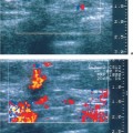
The various causes of attenuation explain why an acoustic shadow is frequently seen deep to carcinomas that have a heterogeneous internal structure (Fig. 1.1). Acoustic shadowing is an important feature to be applied in lesion analysis. The many fibrous elements present in scars lead to diffuse sound refraction, causing the tissue to appear hypoechoic and cast an acoustic shadow (Fig. 1.2). It is important to understand the cause of this phenomenon, because external compression can be applied to the breast with the transducer to flatten out the fibrous structures and decrease the refraction artifacts, bringing out the internal structural details of the scar tissue and diminishing acoustic shadowing (Fig. 1.3). This is a useful technique for helping to differentiate scar tissue from a malignant tumor.
Acoustic Enhancement
The structures located behind fluid and homogeneous tissues generally appear brighter (whiter) than other structures, creating an impression that the echoes have been amplified (Figs. 1.4, 1.5). In reality, however, the amplitude of the sound has not changed. When sound traverses a structure that absorbs less acoustic energy than surrounding tissues, the area located behind that structure will appear relatively brighter than its surroundings. This acoustic enhancement phenomenon is a typical feature of cysts and homogeneous solid masses, such as lymphomas.
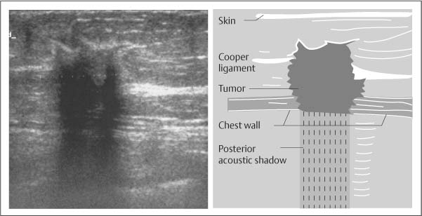
Fig. 1.1 Heterogeneous breast carcinoma with posterior acoustic shadowing. Sound is diffusely scattered within the heterogeneous internal structure of the tumor. The scattering, along with sound absorption in the tissue, creates a posterior acoustic shadow, associated with approximately 60% of primary breast carcinomas.
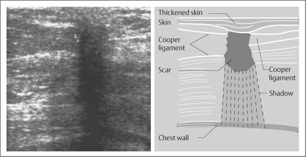
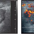
Fig. 1.2 Surgical scar with shadowing. The numerous connective tissue elements in this scar scatter the sound. Because of the refraction and attenuation, the scar appears hypoechoic and casts an acoustic shadow.

Fig. 1.3 Effect of compression. The same scar as in Fig. 1.2, but with slight pressure applied with the transducer. The external pressure flattens the connective tissue structures, improving sound penetration and reflection. This reduces acoustic shadowing and improves delineation of the internal structures. Scars also may change shape in orthogonal projections.
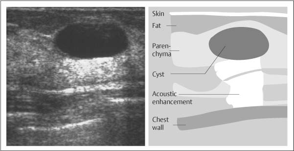
Fig. 1.4 Simple cyst with acoustic enhancement. Sound absorption in the surrounding parenchyma is higher than in the cyst. TGC (time gain compensation) corrects for the absorption, causing an apparent enhancement of echoes behind the cyst, where less attenuation occurs.
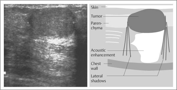
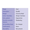
Fig. 1.5 Typical fibroadenoma. This solid, circumscribed homogeneous mass oriented parallel to the skin is less attenuating than the breast tissue, producing an acoustic enhancement effect similar to that in Fig. 1.4. Some complicated cysts with low-level internal echoes have a similar appearance.
Sound is attenuated as it travels through tissue, and ultrasound scanners (p. 12) can correct this effect with time gain compensation (TGC), which boosts the amplitude of echoes that are returned from more distant sources and can decrease overly bright echoes from superficial structures. A uniform brightness level is created over the full depth of the image, helping to improve the diagnostic quality of the image.
Technical Aspects of Ultrasound Equipment
Pulsed Sound Waves
When a continuous sound wave (constant tone) is emitted, there is no way to calculate the travel time of the sound. To generate an image, it is necessary to transmit the sound in pulses of brief duration. The piezoelectric crystal in an ultrasound transducer is caused to vibrate by electronic impulses. A damping material at the back of the crystal limits the duration of the vibration, causing a short ultrasound pulse to be emitted. This pulse travels through the tissue, and sound waves are reflected back to the transducer from various depths. The reflected sound waves (echoes) that return to the transducer set up new vibrations in the piezoelectric crystal, which are converted to electrical signals. Given the relatively constant speed of sound in tissues, the time interval between the transmission and reception of the signal is proportional to the distance of the reflector from the transducer.
Display Modes
An ultrasound pulse can be used to interrogate a series of reflectors situated along a straight line. The different amplitudes that are received from various depths correspond to the impedance differences that are encountered in the tissues. The echoes registered along the path of the ultrasound pulse can be plotted on the x-axis of a monitor and their amplitudes on the y-axis to generate a one-dimensional sectional image. This display mode, in which distance is represented on the horizontal axis and amplitudes on the vertical axis, is called A-mode or amplitude modulation (Fig. 1.6). In the early years of ultrasound development, this was the only mode available for echo signal display. The disadvantage of the A-mode trace is that it makes spatial and anatomic orientation difficult. Its advantage is that it allows the precise measurement of echo amplitudes. The sharp amplitude peaks provide accurate reference points for measuring transducer-to-reflector distances, and therefore A-mode is still used today for various applications.
Instead of displaying the different amplitudes of a one-dimensional image along the vertical axis, the amplitudes can be represented as spots of varying brightness: lower amplitudes appear darker, and higher amplitudes appear brighter. In this brightness-modulated mode, the one-dimensional display can be swept across the screen to depict changes along a temporal axis. This M-mode or motion mode is commonly used in echocardiography. The two-dimensional display represents the motion of the different tissue structures along a temporal axis (Fig. 1.7).
In the B-mode (brightness modulation) technique, multiple brightness-modulated lines of ultrasonic beams are displayed adjacent to one another on the monitor. This creates a two-dimensional sectional image in which different echo amplitudes are represented as different shades of gray, optimized by a broad dynamic range that offers the opportunity to perceive subtle differences in tissue echogenicity.
Real-time, gray-scale, B-mode display is currently the mainstay of diagnostic sonography. The impression of motion is obtained by rapid production of numerous individual two-dimensional images viewed in rapid sequence at rates of 15–60 frames per second.
Focusing
Various transducer design principles are employed in two-dimensional ultrasound imaging. The selection of a transducer for a particular imaging application is guided by its characteristic field of view and the way in which the sound beam can be steered. If the beam were not focused, the sound waves would diverge in a conical pattern and it would not be possible to accurately locate adjacent reflectors and portray them as separate structures. Beam focusing is critical for achieving acceptable lateral resolution. Different transducers employ a variety of focusing methods, such as mechanical rotation, oscillation of the transducer, or electronic steering.
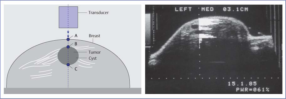
Fig. 1.6 Schematic diagram and monitor display of the A-mode (amplitude modulation) technique. This mode registers the echo amplitudes that are detected along one image line, producing a one-dimensional display of the sound amplitudes. Because the A-mode image does not provide anatomic orientation, it has been superimposed over a two-dimensional B-mode image of the breast. The image demonstrates a cyst. The one-dimensional display of echo amplitudes in the A-mode image shows a circumscribed anechoic area, representing the cyst, flanked by high-amplitude echoes from the adjacent parenchyma. Acoustic enhancement accounts for the slightly higher amplitudes registered behind the cyst. High amplitudes appear bright in the B-mode image, and low amplitudes appear dark.
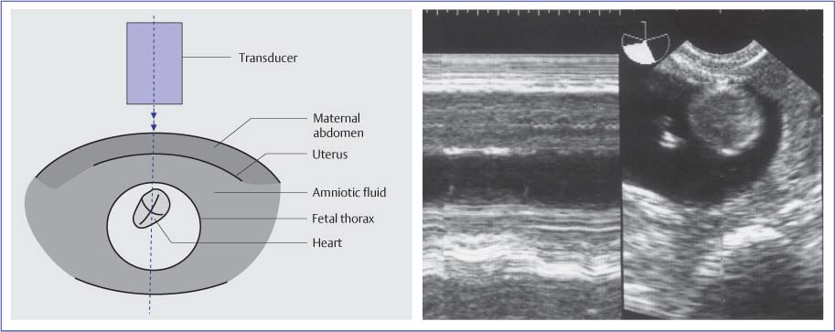
Fig. 1.7 Schematic diagram and monitor display (left) of the M-mode (time–motion) technique, illustrated here for a fetal heart. The motion of brightness-modulated spots is registered along a temporal (horizontal) axis. The echo amplitudes are represented as different levels of gray. Corresponding B-mode image is also shown (far right).
Transducers
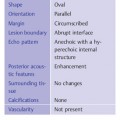
Several types of transducers are available for two-dimensional B-mode imaging, the mode used for most clinical imaging studies (Figs. 1.8–1.11 a–c, Table 1.3). These transducers, along with their advantages and disadvantages in various applications, are discussed below.
Mechanical Sector Transducer
This type incorporates the simplest design principle (Fig. 1.8). A piezoelectric crystal is mounted on a rotation axis and driven by an electric motor that moves the crystal in a short circular or sector-shaped pattern. With each slight change in the crystal angle, a sound pulse is transmitted and received. The pattern of adjacent scan lines results in a sectional image of triangular shape, its apex at the top of the image. The advantage of this transducer is its relatively simple design. Disadvantages are the limited focusing options, the nonuniform field of view, and mechanical wear of the moving parts. The transducer is focused by using a curved piezoelectric crystal or interposing an acoustic lens to narrow the beam. This design results in a fixed focal zone located at a specific depth. One problem is the change in beam width at the near and far sides of the focal zone; variable focusing often cannot be achieved. Some transducers contain two or three crystals with different radii of curvature, providing a limited capacity for focusing at different depths.
Another disadvantage of the sector transducer is that the tissue directly beneath the probe is compressed during scanning. This unequal pressure distribution may displace mobile lesions out of the scan plane. Moreover, the small acoustic window of sector transducers provides more restricted near-field coverage than linear transducers, making sector transducers less useful for systematically surveying the entire breast. When a sector transducer is used for breast imaging, it should be used with a standoff pad to improve the visualization of more superficial structures as well as to obtain a broader and more linear coupling surface. Also, the standoff pad should be of appropriate thickness to place the focal zone of the transducer within the superficial breast layer.
These fixed-focus mechanical sector transducers are no longer commonly used for breast imaging.
|
|
|
|
|
 Mechanical sector transducer
 Electronic linear-array transducer
 Electronic convex-array transducer
 Electronic sector transducer
 Annular-array sector transducer
Electronic Linear-Array Transducer
This transducer incorporates a different design principle. The transducer is elongated and contains many small piezoelectric crystals arranged side by side (Fig. 1.9). Each of these crystals (or small subgroup of crystals) is electronically fired in sequence, and each of the pulsed units transmits and receives one scan line. The parallel arrangement of the scan lines produces a two-dimensional, rectangular image. The time delay between successive crystal firing pulses can be varied as a means of directing and focusing the beam (Fig. 1.10). Pulsing the outer crystals first and then pulsing the inner crystals with a specified time delay results in a convergent sound wave with a variable focal distance. Increasing the pulsing delay between the outer and inner crystals shortens the focal distance and moves the focal point more into the near field. Decreasing the delay moves the focal point deeper in the field. A two-dimensional image is produced not by exciting individual crystals but by pulsing small groups of neighboring crystals in succession, each time shifting the pulsing sequence laterally by one crystal so that an image is built up line by line. The advantages are that the focal distance can be varied electronically, and that multiple focal zones can be produced simultaneously at various depths.
Variable focusing is an important advantage of linear-array transducers. Additionally, the parallel scan lines provide a uniform image field that is as broad in the near field as it is at greater depths. The flat transducer face is also advantageous for evaluating superficial structures, as it provides a relatively uniform coupling pressure at the skin surface. This avoids excessive deformation of the breast that would hamper the evaluation of anatomic structures. Electronic linear-array transducers used for breast imaging generally do not require a standoff pad except for the skin and most superficial tissues, and currently available transducers can focus to depths of less than 1cm in the near field. With older or low-frequency transducers that do not provide acceptable near-field focusing, a standoff pad or thick mound of coupling gel should be used for examining superficial structures.
One disadvantage of linear transducers is that variable focusing is possible only in the image plane, resulting in a greater “image thickness” or slice thickness in the plane perpendicular to it. This adversely affects spatial resolution, although the effect may be difficult to appreciate in two-dimensional sectional images. Sector transducers focus the beam not just in the image plane but also in a circumferential pattern, but the focal zone of these probes is confined to a narrow region.
Electronic Convex-Array Transducer
Convex (curved) arrays are frequently used for abdominal imaging. The crystals are arranged side by side, as in the linear array, but the surface of the transducer is curved. This causes the beams to fan out, producing a trapezoidal image. The advantage over sector transducers is that the image can be electronically modified. As in the linear array, individual crystal groups can be pulsed with different time delays to modify the focal distance. The larger coupling surface provides a broader acoustic window in the near field, which is advantageous for evaluating superficial structures. Also, the scan lines are less divergent than in a sector transducer, resulting in a more uniform image field.
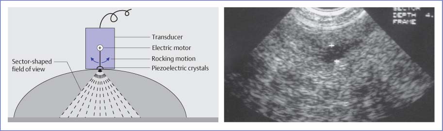
Fig. 1.8
Related posts:
Stay updated, free articles. Join our Telegram channel

Full access? Get Clinical Tree


