1 Basic Tenets of Upper Extremity Ultrasound
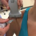
The ultrasound transducer (probe) contains piezoelectric crystals that generate highpitched sound waves (Fig. 1.1) and transmits them to body tissues and receives the returning echoes, providing spatial and contrast information to create an image.
♦ Basic Physics
Sound waves encounter various tissue interfaces such as fluid-muscle or cortical bone-soft tissue interfaces. These interactions result in echoes that create images and/or artifacts. Understanding these allows the operator to eliminate problems and create quality images.
Reflection
The sound beam generated from the transducer travels into variable tissues, striking interfaces (Fig. 1.2). Some beams continue into deeper tissues, and some are reflected directly back to the transducer to be converted to a bright signal. Signal brightness varies with different tissues; some impede the transmission of sound waves (acoustic impedance) more than others. A large difference between two adjacent tissues results in sound waves being intensely reflected back to the transducer.

Fig. 1.1 Frequency spectrum of sound waves. The medical diagnostic frequency is in the 1 to 20 MHz range.

Fig. 1.2 Interfaces. Multiple interfaces created by proximal forearm muscle fascia reflect bright echoes. (Transverse imaging of the proximal forearm with a 15 MHz linear array transducer.) Sub Q, Subcutaneous.

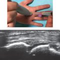
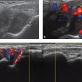
Fig. 1.3 Refraction. Signal loss occurs at the edge of a tendon (white arrows) and the edge of a muscle fascia (yellow arrows), and refractile shadowing occurs deep to this structure as the original sound beam is bent at the sharp margin of the structures. (Transverse imaging of the distal forearm with a 15 MHz linear array transducer.)
Refraction
Refraction occurs when the ultrasound wave is bent and redirected, failing to return an echo signal to the transducer (Fig. 1.3). This may happen when the sound beam strikes the edge of a tendon, resulting in refractile shadowing posterior to the structure.
Attenuation
The ultrasound beam strength is affected by reflection of some of the echoes, refraction, and redirection as well as scatter and absorption. This results in loss of returning echoes in the deeper soft tissues (Fig. 1.4).

Fig. 1.4 Attenuation. A loss of discrete and well-defined echoes occurs in the deeper soft tissues (yellow arrows) as the ultrasound beam is attenuated by the superficial structures and becomes less effective. (Transverse imaging of the distal forearm with a 13 MHz linear array transducer.)

Fig. 1.5 Time gain compensation. (a) Multiple sliding buttons allow manual adjustment of the gain at multiple depths of the image to even the gray scale over varying depths. (b) The echoes and gray scale appear even (yellow arrows) from superficial to deep. (Transverse imaging of the distal forearm with a 13 MHz linear array transducer.)
Time Gain Compensation
To maximize the detail as much as possible, many modern ultrasound units have an option to adjust the gain in specific segments of the image. This allows amplification of the weaker, deeper returning echoes (Fig. 1.5).
♦ Equipment
Various brands and styles of ultrasound machines are currently available (Fig. 1.6). They vary in size, portability, image quality, capability, ease of use, and price. Selection of the proper unit is an individual choice.
Once a decision has been made, the equipment needs to be optimized for use. Practice with the individual unit is essential before it is used with a patient.
The following should be considered when purchasing (or leasing) an ultrasound machine:
• How will the ultrasound machine be used? What is the user’s specialty and specific use?
• What special features are desired?
• What transducers are needed?
• What software options are needed?
• How much portability is necessary?
• What is the budget for this purchase or lease?
Optimal Image Quality
Proper Transducer
A wide variety of frequencies and shapes are available (Fig. 1.7). The frequency is related to the depth of imaging and quality possible (Fig. 1.8).
1. Low frequency (5-7 MHz)
a. Results in excellent depth of image but low resolution
b. May be curvilinear or linear; lower frequency is used to cover a larger area and more depth

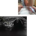
Fig. 1.6 Ultrasound machines. A portable ultrasound machine (a) offers various standard functions and is price friendly but may lack the sophistication and range of functions seen in a more expensive full-size standard diagnostic unit (b).
a. Results in high resolution but less depth
b. Linear with variable size heads; a smaller head linear transducer (“hockey stick”-shaped probe) is excellent for superficial structures
Therefore selection of the proper transducer for the area to be scanned is essential.