11 Evaluation of Distal Biceps
Anterior Approach
♦ Setup
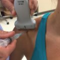
• The patient is seated in a chair with the arm placed on a table between the operator and the patient (Fig. 11.1).
• The table should be draped with a towel or sheets to increase patient comfort.
• The elbow is extended and the forearm supinated.
• A high-frequency (12-15 MHz) linear transducer is used for the examination. A high-frequency small-footprint transducer (hockey stick) can be used as needed.

Fig. 11.1 Patient setup for the distal biceps anterior approach. The patient’s arm is placed on the examination table with the elbow extended and the forearm supinated.
♦ Landmarks
The following landmarks should be noted (Fig. 11.2):
• Medial epicondyle
• Brachial artery
• Distal biceps tendon
♦ Probe Positioning
Transverse, Short Axis
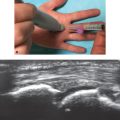
• The probe should be placed on the ventral aspect of the distal upper arm perpendicular to the long axis of the arm (Fig. 11.3).
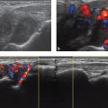
• At this level, the biceps brachii is identified superficial to the brachialis (Fig. 11.4a).
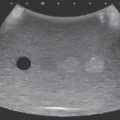
• Keeping the probe perpendicular to the long axis of the arm, scanning proceeds distally until the biceps tendon is visualized lateral to the neurovascular bundle(Fig. 11.4b).
• The tendon is relatively hyperechoic with a fibrillar pattern.
• The identity of the biceps tendon is confirmed by using anisotropy. Changing the orientation of the transducer in the cranial-caudal dimension will cause the echogenicity of the tendon to transition from hyperechoic to hypoechoic.
• Scanning continues distally until the insertion of the biceps tendon on the radial tuberosity is identified. As the tendon dives deep to the insertion, taking an oblique course, the ultrasound beam is angled cranially to keep the tendon fiber long axis perpendicular to the ultrasound beam (Fig. 11.4c-f).
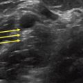
• The lacertus fibrosus (biceps aponeurosis) can be visualized as a thin hyperechoic band extending from the biceps tendon to the superficial fascia of the medial forearm (see Fig. 11.4b).

Fig. 11.2 Surface landmarks for the distal biceps anterior approach. Yellow circle, Medial epicondyle; red line, brachial artery; yellow line, distal biceps tendon.


Fig. 11.4 (a-f) Transverse evaluation of the distal biceps tendon using the anterior approach. The serial images progress from proximal to distal detailing the distal biceps tendon. The lacertus fibrosus is indicated by the thick arrows. B, Biceps; Br, brachialis; BT, biceps tendon; H, humerus; NVB, neurovascular bundle; R, radius; RT, radial tuberosity; U, ulna.
Longitudinal
• The probe is placed on the ventral aspect of the antecubital fossa parallel to the long axis of the arm (Fig. 11.5).
• The brachial artery is identified, with color Doppler if necessary.
• The transducer is moved laterally until the biceps tendon is identified (Fig. 11.6a).
• Alternatively, the biceps tendon is identified in the transverse plane and then the transducer is rotated 90 degrees into the longitudinal plane with the tendon kept in view.
• In the longitudinal plane the tendon is followed proximally to the myotendinous junction.
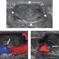
• Finally the tendon is followed distally until the insertion of the biceps tendon on the radial tuberosity is identified (Fig. 11.6b-d).
• Extended-field-of-view applications can be used to visualize the distal tendon from the myotendinous junction to the radial tuberosity insertion in a single image (Fig.11.6e).


Fig. 11.6 Longitudinal evaluation of the distal biceps tendon (solid white arrows) using the anterior approach. (a-d) Serial images from proximal to distal detailing the distal biceps tendon. (e) Extended-field-of-view image of distal biceps tendon. Br, Brachialis; C, capitellum; H, humerus; RH, radial head; RT, radial tuberosity.
Lateral Approach
♦ Setup
• The patient is seated in a chair with the arm placed on a table between the operator and the patient (Fig. 11.7).
• The table should be draped with a towel or sheets to increase patient comfort.
• The elbow is flexed to 90 degrees, and the forearm is supinated. The medial surface of the elbow should rest on the table.
• A high-frequency (12-15 MHz) linear transducer should be used for the examination. A high-frequency small-footprint transducer (hockey stick) can be used as needed.
♦ Landmarks
• Lateral epicondyle (Fig. 11.8)
• Radial head
• Distal biceps tendon

Fig. 11.7 Patient setup for the distal biceps lateral approach. The patient’s arm is placed on the examination table with the elbow flexed and the forearm supinated. The medial aspect of the elbow is placed on the table to expose the lateral surface of the elbow.

Fig. 11.8 Surface landmarks for the distal biceps lateral approach. Yellow circle, Lateral epicondyle; blue circle, radial head; yellow line, distal biceps tendon.
♦ Probe Positioning
• The probe should be placed on the lateral aspect of the upper arm, parallel to the long axis of the arm at the level of the elbow (Fig. 11.9).
• The radial head should be identified and then the probe moved distally down the radius until the radial tuberosity and the insertion of the biceps is observed (the probe moves ventrally in relation to the upper arm because of elbow flexion).
• The distal insertion is along the deep surface of the radius, with portions obscured by shadowing (Fig. 11.10).
• The biceps tendon can be followed proximally to the myotendinous junction.
• Dynamic imaging (pronation and supination of the forearm) can be used to further assess the distal insertion of the biceps tendon (Video 11.1).
• The tendon can also be evaluated in the transverse plane as needed.