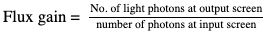
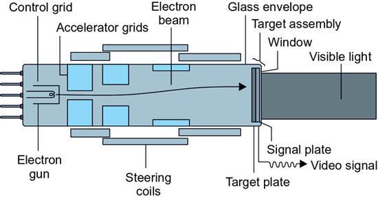
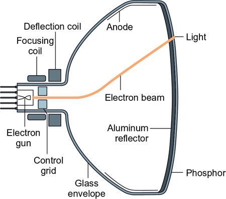
Ankita Aggarwal, Rohini Gupta Ghasi, Padma V. Badhe Mozart’s music is like an X-ray of your soul – it shows what is there and what is not. Issac Stern FLUOROSCOPY-BASICS OF FLUOROSCOPIC IMAGING SYSTEM Fluoroscopy is a real-time imaging investigation which utilizes X-rays for imaging and detects internal motion of fluids or devices. Fluoroscopy has come a long way from dark room days when the images were too dim, to the modern era where no dark room is required and the images can be recorded. This has been made possible with the advent of image intensifiers (IIs) and flat panel detectors (FPDs). There has been a drastic reduction in radiation dose to the patient as well as to the operator due to avoidance of close contact of operator to the screen. With the advancements in cross-sectional imaging techniques, the use of fluoroscopy has largely been overtaken; however, it retains a diagnostic role in many conditions. Although the radiation exposure with fluoroscopy is less than radiography, prolonged exposures can result in large cumulative dose. Hence fluoroscopy should be judiciously used after thorough screening of the clinical indication. This chapter covers the development and components of fluoroscopy and basic principles. In early days of its inception, the fluoroscope had an X-ray tube and fluorescent screen, which produced a very dim image. Hence the technician had to stay in the dark room and wait for at least 10 minutes for retinal adaptation before conducting fluoroscopic examination. The initial fluorescent material used in the screen was barium platinocyanide, followed by cadmium tungstate and later zinc–cadmium sulphide. The technician/radiologist would place himself in front of the patient. X-ray tube would be behind the patient and screen would be between the patient and the technician. Lead covering was provided over the screen to reduce radiation exposure to the technician. To overcome the shortcoming of dull images, IIs were developed in 1953, which dramatically improved the brightness of image and contrast resolution, thereby omitting the use of dark room. These IIs were coupled to optical mirrors to view the final image. A major drawback with this system was narrow-viewing angle, which required the technician to move often with movement of II. Also the images could be viewed by only one person at a time, and no storage of image was possible. The X-ray generator used here is quite similar to that of radiography with additional features as follows This is similar to that used in radiography. It converts electrical energy into X-ray beam. Electrons produced from negatively charged cathode (heated filament) move towards positively charged anode. X-rays are produced when electrons strike the anode. The area where the electrons strike is called the focal spot. Two sizes of focal spot can be there with larger one having size of 1–1.2 mm and smaller one having a size of 0.3–0.6 mm. Smaller focal spot is advantageous for sharper images. Anode is usually placed at an angle of 7–20 degrees to reduce the size of focal point. Vacuum is created within the X-ray tube, and further outer shielding is provided by the metal. Fluoroscopic X-ray tube must be capable of producing continuous (continuous fluoroscopy) as well as bursts of X-rays (pulsed fluoroscopy). A grid-controlled X-ray tube is required for pulsed fluoroscopy, which reduces the radiation dose markedly. Efficient heat-dissipating system is essential for fluoroscopy due to rapid image acquisition. High-speed anodes, coolers, and water or oil exchangers are provided to achieve this purpose. These are provided between X-ray tube exit port and collimator to attenuate low-energy X-rays, as they only increase the patient radiation dose and have no role in image formation. Aluminium or copper is used as the filtering material. Half value layer (HVL) is measured for determining the penetrating ability of X-rays. It is the thickness of the material which will attenuate half the rays passing through it at a specific kilovoltage. It is generally between 2.3 and 3 mm Al at 80 kVp for fluoroscopy. In some systems, the operator can chose between high-dose and low-dose modes while in others it is automatically adjusted depending on beam attenuation and image brightness. This is essential to reduce the radiation exposure to the patient, scatter radiation and glare from the edges. It makes the images sharper. It can have shape varying from round to rectangle depending on shape of image receptor and shutters the X-ray beam to the size of field of view (FOV). The collimators are just larger than the field of view. They adjust depending on source to image distance (SID) so as to prevent any radiation outside the FOV. This is made up of carbon alloys which provide high strength to bear the weight of the patient and at the same time has minimum radiation absorption as that would increase the radiation dose of the patient and reduce the contrast resolution of the image. Foam pads may be used in between the table and the patient for the patient’s comfort without further increasing the radiation dose. Grids are provided to decrease the scatter radiation to image receptor and thus increase contrast resolution. They, however, increase the radiation dose. The grid ratio is 6:1 to 10:1 for fluoroscopy. It can be removed when the area of interest is small. It can be circular or rectangular in shape. There is reduction of radiation dose by about 50% when grid is removed. The role of II is to convert the X-rays into small image having a large brightness gain. All the components of II are within a vacuum tube made up of ceramic which further has a metal housing to protect from external magnetic field or light source. The various components, shown in Fig. 1.7.1.2, are described as follows: It further has four parts (Fig. 1.7.1.3): (Made up of metal or glass): It is convex in shape and made up of aluminium or titanium. X-rays pass through this to the substrate. The size of input windows can vary from 10 to 40 cm depending on the area of the body part to be imaged. (Made up of aluminium). Phosphor (made up of sodium activated caesium iodide): It converts X-rays into light photons which have very high X-ray absorption capacity to the tune of 70%–80%. These are needle-shaped crystals with a size of micrometer and having fibre-optic characteristics. The layer of CsI: Na is ~400–500 μm thick and is laid over aluminium substrate. Each X-ray can produce up to 300 light photons in blue spectrum. It is made up of a thin layer of antimony caesium alloy which absorbs fluorescent light emitted from input phosphor, matching to the blue spectrum. It absorbs light photons to emit electrons in II. One X-ray photon can release up to 200 electrons at 60 KeV. Multialkali photocathodes containing sodium, potassium and caesium are much more effective than single-alkali photocathodes, as they emit thrice the number of photoelectrons. Electron lens which steers, focuses, and accelerates electrons from cathode to anode. Anode and three electrodes which create negative potential of about 25 kV to accelerate and focus the electrons towards the anode and output screen. It has output phosphor which converts electron beam into visible light photons and the output window through which the beam moves out of the II system. The output beam is 1/10th the diameter of input screen, thereby minifying the image. Also the image is inverted upside down at the output screen. Activated silver-activated zinc cadmium sulphide (ZnCdS:Ag) crystals are coated on the inner surface of output window. It is about 25–35 mm in diameter and few micrometers thick. There is a thin coating of aluminium in the output screen to prevent light from back emission to cathode by phosphor. Overall there is brightness gain of 5000–20,000 due to rapid acceleration of the electrons and reduction in width of the output beam as compared with the input rays. Brightness gain is defined as the ratio of brightness of output screen to that of input screen. It can vary from 5000 to 3000. G(brightness) = G(minifaction gain) × G(flux gain) Minifaction gain is the increase in the brightness of the image due to demagnification: G ( minifaction gain ) = { Diameter of input screen diameter of output screen } 2 Flux gain is gain due to difference in voltage at two ends. Higher the difference, the greater the flux gain. The images can be magnified with II by focussing a small part on to the larger output image screen. Flux gain = No. of light photons at output screen number of photons at input screen These days, brightness gain is replaced by II conversion factor (Gx) due to difficulty in measuring the brightness of input screen. Gx = Luminance of output screen ( candela / m 2 ) dose rate of II input ( microgray / sec ) The conversion factor can vary from 50 to 300. The higher the conversion factor, the more efficient the II. It is the ability to resolve fine details. Due to convexity of the input screen of II, spatial resolution is greater at the centre than at the periphery of the input screen. It is around 4 lines/mm at 25 cm mode for CsI II. It is the brightness of the image at the periphery to that at the centre of output screen. It is generally in the range of 20:1 and can vary from 10:1 to 30:1. Image noise is high in II due to low mAs. To reduce the noise, mAs have to be increased, which will proportionately lead to rise in radiation dose. CsI input phosphor due to its inherent high DQE produces little noise with good quality images. It is the persistence of emission of light from the screen even when the radiation beam has been switched off. It is the reduction in brightness at the periphery of the image than the centre due to which image formed at the centre is sharper. It is produced due to scattering of light in the II. This results due to the presence of electromagnetic field near the II. This occurs with the rectangular grid due to curved nature of the input screen within II. Beam-splitting mirror is provided, which splits the light photon beam and transmits the visible light photons from output layer of II partially to the recording video camera (~10%) and rest to the photospot film camera (90%) for viewing. Another small mirror is present between collimating lens and beam splitting mirror, which transmits part of beam to automatic exposure control sensor (Fig. 1.7.1.4). Depending on the size of aperture through which the rays pass, radiation exposure as well as noise can be controlled. The coupling can also be done with a bundle of fibre optics, which, though is compact and easy to handle, cannot have additional optics for photospot camera. Modern fluoroscopic units are linked to television monitor for many people to view the images simultaneously and also linked to the recording systems for storage and postprocessing. Image can be modified by controlling its brightness and contrast level. It is a closed circuit consisting of a video camera, which converts light image into voltage signal, and a monitor, which converts this voltage signal into display image on the monitor (Fig. 1.7.1.5). These are connected by a coaxial cable. Video camera is a thermionic television camera tube, which is cylindrical in shape and has vacuum inside. It has two parts: one is the photoconductive target and other is the electron beam. Photoconductive target is the one on which optical coupling devices project the photon image from the II output and form a latent image. This latent image is scanned by the electron beam forming an electronic signal, which is the image in the form of raster lines. This is further converted into an image by the display monitor. Examples of television camera tube are vidicon and plumbicon: it is modified version. A classical vidicon (Fig. 1.7.1.6) is composed of a glass envelope to maintain vacuum. Inside, there is a cathode end consisting of an electron gun and anode end on the other side, formed by the target assembly. Electron gun is a heated filament, which, by thermionic emission, gives constant electron current. It is surrounded by a control grid which accelerates these electrons towards the anode. Electron beam further passes through electrostatic grids, which further accelerate and focus the electron beam. This is followed by multiple electromagnetic coils (deflection, focussing, alignment coils) which control the size and position of electron beam. Electron beam then reaches the target assembly (anode end), which is composed of three parts: target plate, signal plate and window. Target plate is composed of a photoconductive antimony trisulfide which is swept by the electron beam. This is followed by signal plate which is composed of a thin layer of metal or graphite which conducts video signal out of the tube through window (thin part of glass envelope) to the external video circuit. These days, conventional cameras are replaced by more robust, smaller and powerful charge-coupled devices (CCDs), which consist of an array of solid light sensors which convert light image into pixels which are further read out as voltage signals representing image. A layer of crystalline silicon acts as the sensitive component, which produces electrical charge when illuminated, which is then sampled to produce an image. Major advantages of CCDs as compared with conventional video cameras are no image lag, absence of spatial distortions, wider dynamic range (3000:1), high SNR and better contrast resolution. All these features help in reducing the patient radiation dose. Video monitor converts video signal into visible image. It has a television picture tube (Fig. 1.7.1.7), which is also called cathode ray tube. The composition is same as that of video camera tube except it is larger in size and the anode is composed of a fluorescent screen and a graphite lining. The electron beam intensity in picture tube is modulated by the control grid, which is then accelerated and focussed onto the output phosphor screen resulting in burst of light. The phosphor screen is composed of linear crystals with thin aluminium coating. These are arranged perpendicular to glass envelope, thereby preventing lateral dispersion.
1.7: Basics of fluoroscopy
Uses
Development
Advancements in fluoroscopy
Components of fluoroscopy machine (Fig. 1.7.1.1)
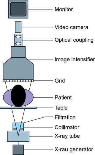
1. X-ray generator
2. X-ray tube
3. Filters
4. Collimator
5. Patient table
6. Grids
7. Image intensifiers
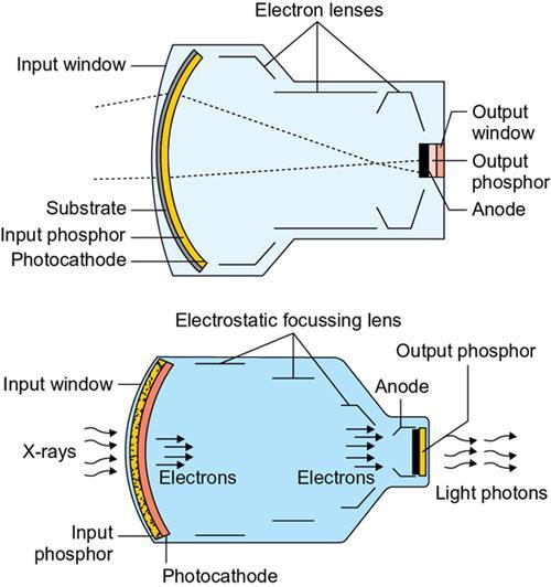
a. Input layer
Input window.
Substrate.
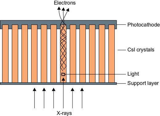
Input.
Cathode.
b. Electron lens
c. Anode
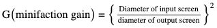
d. Output layer
Properties of image intensifier
Spatial resolution.
Contrast resolution.
Noise.
Artefacts
Image lag.
Vignetting.
Veiling glare.
S distortion.
Pincushion distortion.
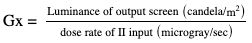
8. Optic coupling devices
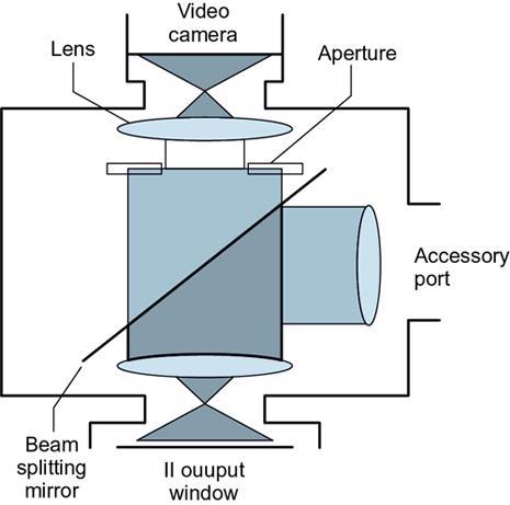
9. Television monitor and image recording systems
Video camera
Video monitors
Related posts:


Stay updated, free articles. Join our Telegram channel

Full access? Get Clinical Tree


