, Bernd Heinzl1 and Michael Riccabona2
(1)
Division of Pediatric Cardiology, Department of Pediatrics and Adolescent Medicine, University Hospital Graz, Auenbruggerplatz 34/2, Graz, 8036, Austria
(2)
Division of Pediatric Radiology, Department of Radiology, University Hospital Graz, Auenbruggerplatz 34, Graz, 8036, Austria
5.1 Introduction
5.2.1 Transducers
5.2.2 Standard US Techniques
5.2.3 Patient Position
5.2.4 Sedation
5.4.1 Parasternal Views
5.4.2 Apical Views
5.4.3 Subcostal Views
5.5 Other Techniques
5.5.2 Doppler Sonography
5.6.4 Contrast-Enhanced US
5.7 Normal Values
5.9.1 Cardiomyopathies (CMP)
5.9.2 Acute Myocarditis
5.9.5 Kawasaki Disease
5.9.6 Intracardiac Thrombi
5.9.7 Cardiac Tumours
5.10.2 Cardiac MRI and CT
5.11 When to Do What
5.11.2 Trauma and Emergency
Abstract
Most important non-invasive tool for evaluation of the child’s cardiovascular system provides exact morphological diagnosis and enables hemodynamic assessment in most cases – often avoiding invasive diagnostic heart catheterisation.
Abbreviations
Ao
Aorta
AS
Aortic stenosis
ASD
Atrial septal defect
AVSD
Atrioventricular septum defect
CMP
Cardiomyopathy
Co A
Aortic coarctation
CW-Doppler
Continuous wave Doppler
PW-Doppler
Pulsed wave Doppler
DORV
Double outlet right ventricle
IAS
Interatrial septum
IVS
Interventricular septum
LA
Left atrium
LV
Left ventricle
PA
Pulmonary atresia
PDA
Patent ductus arteriosus
PS
Pulmonary stenosis
PV
Pulmonary vein
RA
Right atrium
RV
Right ventricle
TAPVR
Total anomalous pulmonary venous return
TGA
Transposition of the great arteries
TOF
Tetralogy of Fallot
UVH
Univentricular heart
VSD
Ventricular septum defect
5.1 Introduction
Most important non-invasive tool for evaluation of the child’s cardiovascular system, provides exact morphological diagnosis and enables hemodynamic assessment in most cases – often avoiding invasive diagnostic heart catheterisation.
5.2 Equipment Needs and Specific Considerations
5.2.1 Transducers
Age and size of patients from preterm infants to adolescents – variety of (mostly sector) transducers necessary to fulfil all imaging requirements:
8–10–12 MHz transducer for good near-field resolution in premature/newborn infants, in this age also linear transducers can be used.
5–3 MHz transducer for far-field penetration and high-flow velocities in older children/adults.
5.2.2 Standard US Techniques
M-Mode.
Two-Dimensional Ultrasound (2DUS).
Continuous Wave Doppler (CW-Doppler).
Pulsed Wave Doppler (PW-Doppler).
Colour Doppler Sonography (CDS).
5.2.3 Patient Position
Ideally transthoracic echocardiography is performed in reclined position with patient lying left side down – to avoid interference from lung tissue (especially in older children). A supporting pillow helpful.
For suprasternal views neck has to be hyperextended to gain access.
5.2.4 Sedation
Transthoracic echocardiography is mostly feasible without sedation.
Sometimes sedation is essential to obtain accurate diagnostic information.
5.3 Standard Planes and Standardised Course of Examination
Three Basic Planes:
Long-axis plane parallel to major axis of left ventricle (LV).
Short-axis plane orthogonal to major axis of LV.
Coronal plane through cardiac apex (four-chamber view).
Transducer positioned to four echocardiographic windows to obtain planes (Fig. 5.1):
Fig. 5.1
Schematic drawing of typical transducer positions for echocardiography. Suprasternal, parasternal, intercostal, apical and subcostal window, with respective transducer orientation
1.
Parasternal area near to sternum in second, third or fourth intercostal space.
2.
Region of cardiac apex.
3.
Subcostal region.
4.
Suprasternal notch.
Long or short axis plane can be generated in each of these areas. Moreover, additional views are obtained by tilting transducer from right to left, from superior to inferior, or rotating clockwise and counterclockwise.
Ideally every examination should follow standardised protocol:
1.
Define visceral situs, describe relationship between descending aorta and inferior vena cava (IVC).
2.
Specify position and morphology of atria.
3.
Describe systemic and pulmonary venous return, hepatic veins, continuity of IVC and interatrial septum (IAS).
4.
Assess atrioventricular junction: atrioventricular valves and interventricuar septum (IVS).
5.
Ventriculoarterial junction: origin and course of great vessels.
5.4 Normal 2D Echocardiogram Findings
5.4.1 Parasternal Views
5.4.1.1 Parasternal Long Axis View (Fig. 5.2)
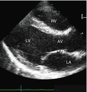
Fig. 5.2
Long axis view. Part of right ventricle (RV) seen behind chest wall. Inflow part of left ventricle (LV) with mitral valve (MV) as well as outflow tract of LV with aortic valve (AV) depicted; LA left atrium
Obtained by applying transducer to second till fourth intercostal space, orienting plane along major axis of heart – from left hip to right shoulder – right ventricle (RV) and outflow-tract of LV can be identified.
In infants thymus seen between thoracic wall and heart-improves visualisation and enlarges sonographic window.
Next structures: interventricular septum, left ventricle and atrium; inflow portion of left ventricle with mitral valve, outflow portion with aortic valve and ascending aorta – visualised in same plane.
5.4.1.2 Parasternal Short Axis Views (Figs. 5.3 and 5.4)

Fig. 5.3
Parasternal short axis view at base of the heart. Aorta (Ao) visualised in cross section, pulmonary artery (PA) with its bifurcation seen left to Ao
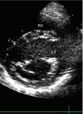
Fig. 5.4
Parasternal short axis view – at level of mitral valve. Left ventricle (LV) depicted in cross section, with leaflets of mitral valve appearing as fish mouth (→) in diastole; RV right ventricle
Obtained by rotating transducer 90° clockwise from long axis view. Several short axis planes can be generated by tilting transducer from apical region inferiorly to base of heart superiorly. Doing this, cross section of LV and part of RV seen at different anatomic levels: cardiac apex, papillary muscles, mitral valve, heart base with origin of great vessels.
Leftward angulation of transducer: RV outflow tract and main pulmonary artery (PA) with its bifurcation visualised.
At base of heart: origin of coronary arteries.
5.4.2 Apical Views
Apical four-chamber view (Fig. 5.5).
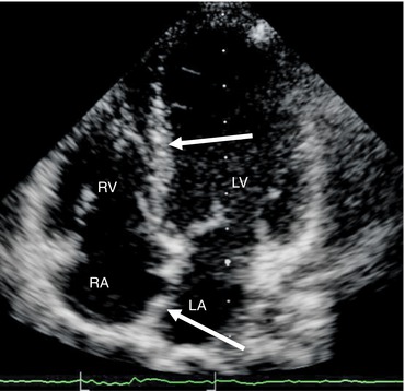
Fig. 5.5
All four chambers of the heart – apical 4-chamber view. Interventricular and interatrial septum (→) seen. LV left ventricle, RV right ventricle, LA left atrium, RA right atrium
Standard apical four-chamber view: transducer applied to cardiac apex, plane oriented perpendicular to atrial and ventricular septa.
All four cardiac chambers, mitral and tricuspid valve, IAS and IVS imaged with anterior angulation of transducer LV outflow tract and ascending aorta visualised (“five-chamber view”).
5.4.3 Subcostal Views
5.4.3.1 Sagittal Subcostal View
Transducer placed in subcostal region in sagittal plane: descending aorta visualised left to IVC.
5.4.3.2 Subcostal Four-Chamber View (Fig. 5.6)
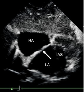
Fig. 5.6
Interatrial septum (IAS) – subcostal view. IAS (→) imaged especially well, RA right atrium, LA left atrium
Transducer applied to subcostal region, plane tilted superiorly: all four cardiac chambers imaged like in apical four-chamber view; especially in newborns and infants, interatrial septum visualised, especially well also drainage of pulmonary veins (PV) can be demonstrated.
5.4.4 Suprasternal View (Fig. 5.7)
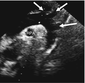
Fig. 5.7
Aortic arch – suprasternal view. Entire aortic arch with origin of supra-aortal vessels (→) imaged, right pulmonary artery (RPA) seen in cross section beneath aortic arch
Transducer placed in suprasternal notch with overextended neck: entire aortic arch with arising supra-aortic vessels visualised. Right PA imaged in cross section beneath aortic arch.
This view particularly helpful for differentiating between left or right aortic arch and assessing supra-aortic great vessels.
5.5 Other Techniques
5.5.1 M (Motion)-Mode Echocardiography
M-Mode – first US application in cardiac imaging; based on 1D view of heart. Amplitude and motion recorded in real time.
Today M-Mode generated from 2DUS, imaging plane used to position M-Mode beam.
Applications of M-Mode in paediatric echocardiography:
Measurement of cardiac chambers, vessels and cardiac septa.
LV systolic function (shortening fraction).
Study of valve motion and interventricular septum.
5.5.2 Doppler Sonography
5.5.2.1 CDS with 2DUS
Demonstrates several aspects of blood flow in heart and great vessels.
Assesses direction of intra- and extracardiac shunts, valvular stenoses and regurgitations.
5.5.2.2 PW- and CW-Doppler
Used in combination with 2DUS and CDS to measure direction and velocity of blood flow in cardiac chambers, great vessels or across intra- and extracardiac shunts.
Advantage of PW-Doppler: ability to sample blood flow in small specific area.
Limitation of PW-Doppler: maximum detectable velocity limited. Therefore CW-Doppler used for quantification of severe stenosis and high flow velocities, etc.Related posts:

Stay updated, free articles. Join our Telegram channel

Full access? Get Clinical Tree