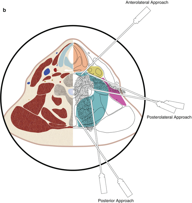
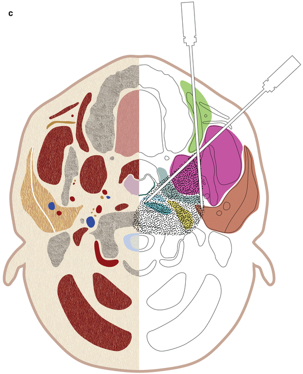
Fig. 22.1
(a–c) Schematic drawings showing the needle trajectories for the anterolateral, posterolateral, and posterior approaches at the (a) C4 and (b) C6 vertebral levels. (c) Schematic drawing showing needle trajectories for the paramaxillary approach for C1 and C2 lesions
Anterolateral Approach
The anterolateral approach allows access to lesions of the mid and lower cervical vertebrae (C4–C7) and discs and to lesions in the prevertebral space [10, 21]. This approach allows easier access to the anterior aspect of the vertebral body and also allows access to the intervertebral disc because it is not hidden by the uncovertebral joint, which is located more posterolaterally. This approach can also be used to access lesions involving the transverse process of the vertebrae as long as the vertebral artery is not in the needle path [22].
For the anterolateral approach, the patient is placed in the supine position with the head turned toward the opposite side, with the neck in extension, and with a pillow or bolster under the shoulders. The needle is inserted anterior to the sternocleidomastoid muscle and is advanced posteromedially between the visceral space and the carotid space (Fig. 22.2) [10, 13, 14, 21]. Care should be taken to avoid the hypopharynx and especially the piriform fossa and esophagus. In some cases, it may be helpful to manually retract the great vessels laterally, especially if the procedure is performed with fluoroscopic guidance [19, 20].
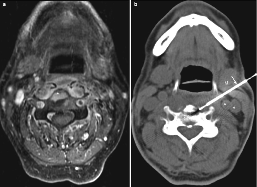

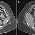
Fig. 22.2
(a, b) Cervical spine. Anterolateral approach. (a) Contrast-enhanced axial magnetic resonance image shows an abnormal area of enhancement (asterisk) in a C4 vertebral body. (b) Computed tomography image during the biopsy procedure shows the biopsy needle (arrow) inserted through the sternocleidomastoid muscle (M) and advanced medial to the carotid artery (A) and jugular vein (V) into the C4 vertebral body
As the needle is pushed posteriorly toward the vertebral body, care should be taken to avoid the vertebral artery. From the subclavian artery, the vessel goes upward toward the foramen in the base of the transverse process of the sixth cervical vertebra and then passes upward through the canal in the transverse processes. Between the foramina, the vertebral artery is located lateral to the mid or posterior part of the vertebral body or disc; care should be taken to avoid the lateral aspect of the vertebral body. Because the needle is directed posteriorly and medially in this approach, theoretically, the spinal canal could be penetrated through the neural foramina, which are directed anterolaterally. However, the use of intermittent CT scans to check the position and trajectory of the needle tip can protect against the penetration of the spinal canal and prevent possible damage to vascular and neural structures. Furthermore, the presence of the carotid sheath tends to keep the needle pointed medially and away from the neural foramen and the vertebral artery [22].
Other important structures that could be in the needle path when this approach is used include the superior and middle thyroid vessels, the superior and inferior laryngeal nerves, the loop of the hypoglossal nerve, and the cervical ganglia of the sympathetic system. However, the small-caliber needles used for the biopsy are unlikely to cause serious damage to the blood vessels or nerves.
Posterolateral Approach
The posterolateral approach is used for sampling lower cervical (C4–C7) vertebral lesions that involve the transverse process, pedicle, articular pillar, or lamina and for sampling lesions in the prevertebral and lateral paraspinal portions of the perivertebral space [7, 19]. This approach can also be used for sampling lateral masses involving C1 and C2.
With the patient in the supine, prone, or lateral decubitus position, the needle is inserted through the sternocleidomastoid muscle and the posterior cervical space and advanced posterior to the carotid sheath (Fig. 22.3). Depending on the vertebral level (mid vs. lower cervical), the patient’s position, and the size and location of the carotid sheath, the needle may be advanced anteromedially or posteromedially. The soft tissues overlying the clavicles and shoulder may interfere with needle placement in the lower neck, particularly in patients with prominent clavicles and short necks. An out-of-plane angled approach with a caudal needle angulation can be used in this situation; the needle is inserted in a plane cranial to the level of the target lesion and advanced caudally and medially (Fig. 22.4).
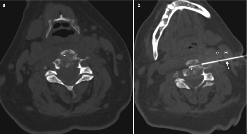
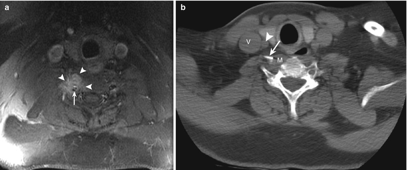

Fig. 22.3
(a, b) Cervical spine. Posterolateral approach. (a) Computed tomography (CT) scan shows a lytic process (asterisk) involving the C3 vertebral body. (b) CT image during the biopsy procedure shows the biopsy needle (arrow) inserted through the sternocleidomastoid muscle (M) and advanced posterior to the carotid sheath vessels (V) into the C3 lesion (asterisk)

Fig. 22.4
(a, b) Cervical spine. Angled posterolateral approach. (a) Magnetic resonance image shows a hyperintense lesion (arrowheads) involving the right transverse process of the C6 vertebra extending into the prevertebral space. The vertebral artery (arrow) is immediately posterior to the mass. (b) CT scan shows the needle tip (arrow) in the prevertebral portion of the mass (M). The needle was inserted at a more cranial level, directed caudally, and advanced posterior to the internal jugular vein (V) and the common carotid artery (arrow)
With this approach, the vertebral artery is the structure most vulnerable to injury during the biopsy, especially at levels between the transverse foramina, where the vessel is located lateral to the vertebral body and disc. Also, a needle inserted behind the carotid sheath and advanced posteromedially toward a lesion involving the seventh cervical vertebra could potentially injure the vertebral artery. Using contrast medium to identify the vertebral artery can reduce the risk of injury. Because the intervertebral foramina run from the spinal canal in an oblique medial-to-lateral and posterior-to-anterior direction, penetrating the spinal canal with this approach is not possible. Furthermore, a small-caliber needle puncture of the brachial or cervical plexus as it runs between the scalene muscles is not dangerous, although it may cause transient pain. When this approach is used for biopsy of C1 and C2 lesions, care should be taken to identify and avoid the vertebral artery (Fig. 22.5).
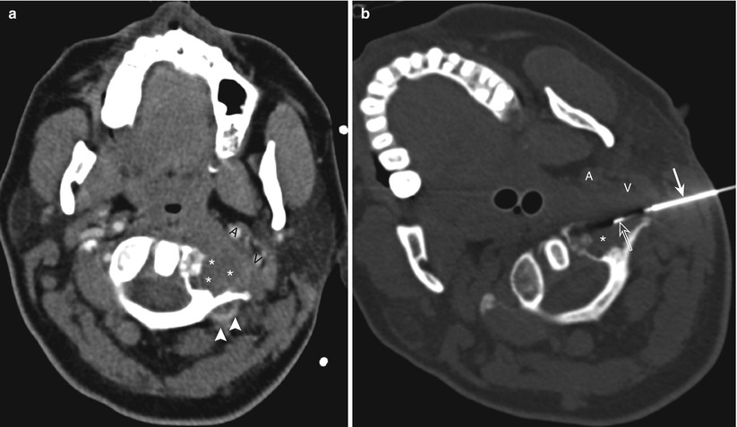

Fig. 22.5
Cervical spine. Posterolateral approach. Use of contrast agent to identify and avoid the vertebral artery. (a) Contrast-enhanced computed tomography scan with the patient in a supine position shows a lytic lesion with soft-tissue extension (asterisks) involving the lateral mass of the C1 vertebra. The carotid artery (A) and jugular vein (V) are displaced anteriorly by the mass. Note the posterior location of the vertebral artery (arrowheads). (b) Computed tomography scan shows the coaxial biopsy system with an outer guide needle (arrow) and an inner core biopsy needle (open arrow) advanced posterior to the carotid artery (A) and jugular vein (V) into the mass (asterisk)
Posterior Approach
The posterior approach is used for biopsy of lesions involving the spinous process, lamina, and articular pillars and processes of the cervical vertebrae as well as lesions in the posterior and lateral paraspinal portions of the perivertebral space [22]. This approach also can be used occasionally for sampling lateral masses involving C1 and C2, provided care is taken to identify and avoid the vertebral artery[22].
With the patient in the prone or lateral decubitus position, the needle is advanced through the posterior paraspinal muscles in an anterior direction toward the target lesion (Fig. 22.6). Risk of injury to major vessels or nerves with this approach is extremely low. During biopsy of lesions involving the laminae, care should be taken to ensure that the needle does not penetrate the spinal canal or thecal sac. For sampling lesions involving a lateral mass of C1 using a posterior approach, the needle should be advanced under the lamina, not above it [22]. The vertebral artery, after exiting the C1 foramen, courses posteriorly along the upper surface of the C1 lamina. If necessary, intravenous administration of contrast medium can be used to help identify and avoid the vertebral artery (Fig. 22.7).
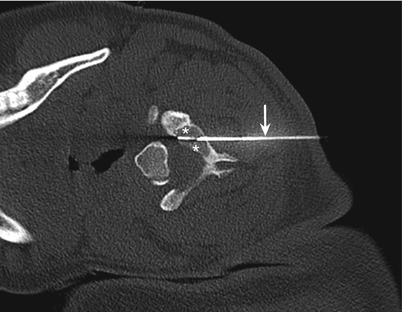
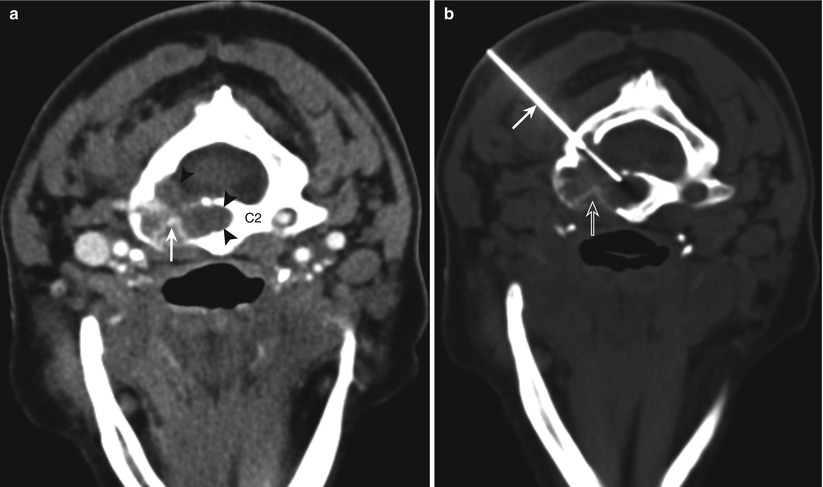

Fig. 22.6
Cervical spine. Posterior approach. Computed tomography scan with the patient in the decubitus position shows the needle (arrow) passing through the posterior paravertebral muscles into a lytic process (asterisks) involving the left lamina of C3 vertebra

Fig. 22.7
Cervical spine. Posterior approach. Use of contrast administration to identify and avoid the vertebral artery. (a) Contrast-enhanced computed tomography scan with the patient in a prone position shows a lytic lesion (arrowheads) involving the body and lateral mass of C2 vertebra. Note the vertebral artery (arrow) encased and narrowed by the lesion. (b) Computed tomography scan shows the biopsy needle (arrow) passing through the anterior portion of the lamina into the lesion posterior to the expected location of the vertebral artery (open arrow)
Transoral Approach
The transoral approach can be used for percutaneous access to lesions involving the anterior portions of the C1 and C2 vertebrae, including the odontoid [19, 22, 23]. The use of this approach requires general anesthesia. An otolaryngologic retractor is placed in order to provide adequate visibility of the oropharyngeal space. The uvula is pushed away with a retractor or a nasal tube. Some operators recommend placement of an inflatable bronchial blocker into the esophagus to prevent antiseptic fluids or blood from entering the stomach. The oral pharynx and cavity is prepared with antiseptic solution. The posterior pharyngeal wall is sprayed and infiltrated with local anesthetic. The needle is inserted through the posterior pharyngeal mucosa and is advanced posteriorly through the retropharyngeal space and prevertebral muscles toward the target lesion (Fig. 22.8). This is a relatively safe approach because no important structure lies between the posterior pharyngeal wall and the bone. Use of antibiotics in this setting is recommended because of the difficulty in maintaining a sterile field with the transoral approach.
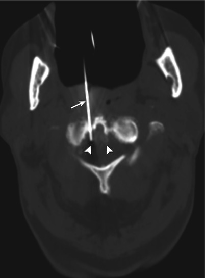

Fig. 22.8
Transoral approach. Computed tomography scan shows the needle (arrow) inserted through an open mouth and advanced through the retropharyngeal and prevertebral tissues into a soft-tissue mass (arrowheads) involving the tip of the odontoid and the anterior arch of atlas
Paramaxillary Approach
Although the presence of facial skeleton precludes the use of the standard anterolateral approach for C1 and C2 lesions, a transfacial paramaxillary approach offers safe anterior access to anterior C1 and C2 lesions [22]. The needle is inserted inferior to the zygomatic process of the maxilla and advanced posteriorly through the buccal space between the maxilla and mandible. The needle is advanced through the lateral and medial pterygoid muscles and the parapharyngeal and retropharyngeal spaces for accessing C1 and C2 lesions (Fig. 22.9).
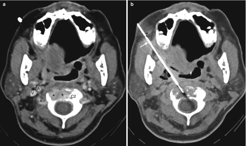

Fig. 22.9
Cervical spine. Paramaxillary approach. (a) Contrast-enhanced computed tomography scan with the patient in a supine position shows a lytic lesion (asterisks) involving the body of C2 vertebra. Note the position of the carotid artery (A), jugular vein (V), and the vertebral artery (VA). (b) Computed tomography scan shows the biopsy needle (arrow) advanced through the masticator, parapharyngeal spaces, and prevertebral muscles into a lytic lesion (asterisks) involving the C2 vertebral body
It is important to avoid the carotid artery; administration of contrast may occasionally be required to visualize this artery. Other structures present in the needle path that could potentially be injured with this approach include the facial artery, internal maxillary artery and its branches, the pterygoid venus plexus, branches of the mandibular and maxillary nerves, and the external carotid artery as it courses laterally deep to the lateral pterygoid muscle. Using a Hawkins-Akins needle (Meditech, Westwood, MA) with a blunt-tip stylet as the outer guiding needle decreases the risk of injury to the vessels and nerves in these spaces [22].
Thoracic Spine
Various approaches can be used for thoracic vertebral biopsies (Fig. 22.10). The vertebral level, the location of the lesion in or adjacent to the vertebral body, and the lesion size are the major determinants to use in selecting an approach. Selection of an approach is also affected by the body habitus and the presence and severity of kyphosis and scoliosis.
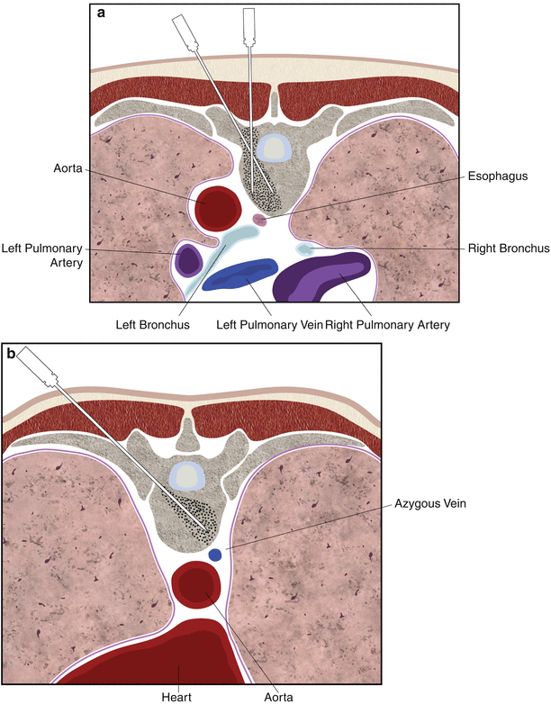
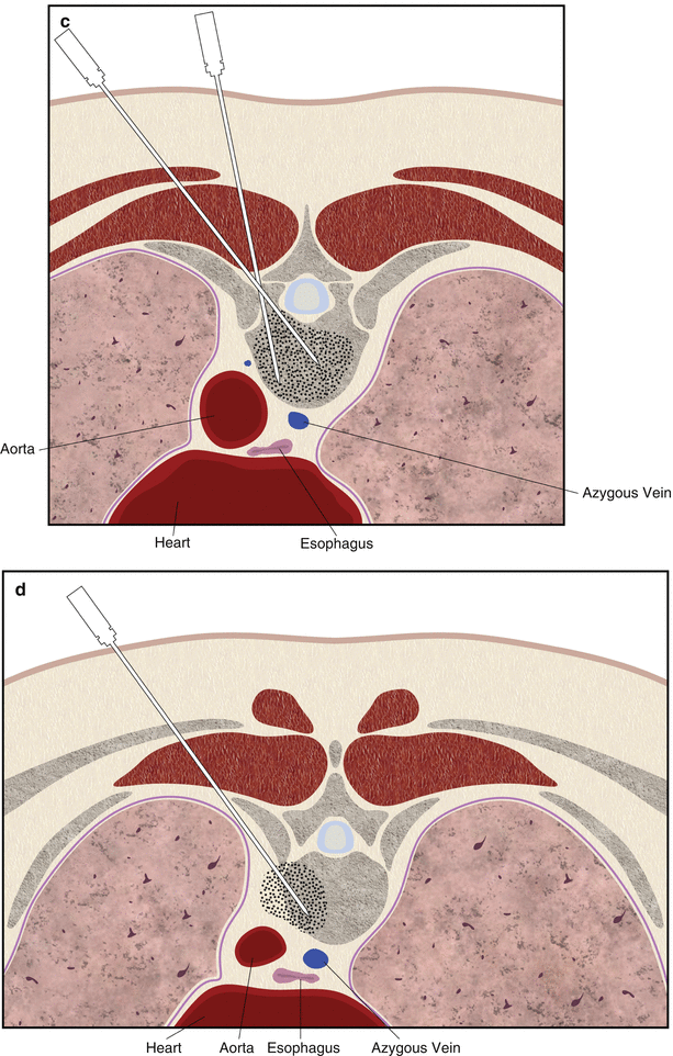


Fig. 22.10
(a–d) Schematic drawing showing needle trajectories for the transpedicular (a), costotransverse (b), costovertebral groove (c), and intercostal (d) approaches for thoracic vertebral lesions. The shaded areas represent the region that can be accessed with each approach
Transpedicular Approach
The pedicle provides a short and safe path to the vertebral body [24]. A transpedicular approach is generally used for lesions located within or just anterior to the pedicle (Fig. 22.11). This approach is also the preferred approach for lesions that involve the entire vertebral body.
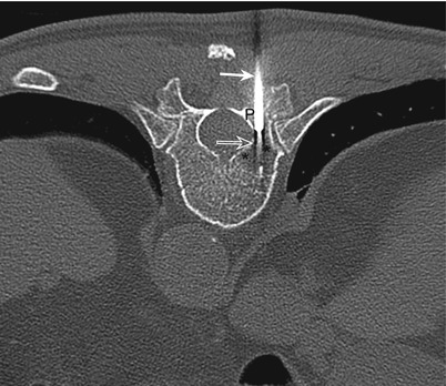

Fig. 22.11
Thoracic spine. Transpedicular approach. Computed tomography scan with the patient in the prone position shows the guide needle (arrow) and the coaxially inserted core biopsy needle (open arrow) advanced through the right pedicle (P) of the T11 vertebra for biopsy of a lytic lesion (asterisks) located immediately anterior to the pedicle
The transpedicular approach avoids risk of injury to major vessels, the thecal sac and the cord, and the nerve roots [25, 26]. Another advantage of the transpedicular approach is that the needle is perpendicular to the bone cortex at the point of entry. In addition, the cortical bone of the posterior pedicle is typically thin, thus facilitating needle insertion. Since the pedicle is attached to the cranial half of the vertebral body, this approach is generally suitable for lesions involving the upper part of the vertebral body. However, the use of craniocaudal needle angulation with this approach, wherein the needle entering the cranial part of the pedicle is angled caudally, allows access to lesions involving the mid to lower part of the vertebral body (Fig. 22.12).
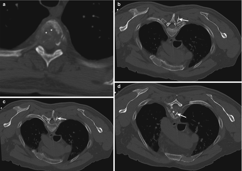

Fig. 22.12
Thoracic spine. Angled transpedicular approach. (a) Computed tomography scan with the patient in the supine position shows a lytic process (asterisks) involving the T5 vertebral body. Note the lesion is located caudal to the level of the pedicle, precluding a direct transpedicular approach. (b–d) The needle (arrow) was inserted at a level cranial to the lesion and directed caudally through the pedicle (P) into the lesion (asterisk)
The transverse diameter of the thoracic pedicle is smaller than that of the lumbar pedicle, leaving less room for error when placing a large-caliber needle through the pedicle [27, 28]. The transverse diameter of the pedicle is smallest (4.6 mm on average) at the T5 level. Thus, a biopsy needle with an outside diameter of 3 mm might injure the medial walls of the pedicle [25]. The small size of the pedicle also restricts the entry angle of the biopsy needle. Although thoracic pedicles generally will accommodate an 11-gauge needle, smaller gauge needles may be preferable, especially at upper and middle thoracic vertebral levels.
Thoracic transpedicular biopsy can be performed with fluoroscopic or CT guidance. Because of the occasional difficulty in visualizing the small thoracic pedicle with X-ray fluoroscopy, CT guidance is the preferred method.
Costovertebral/Transcostovertebral/Costotransverse Joint Approach
For the transcostovertebral approach, the needle is inserted laterally and advanced anteromedially, passing in between the tubercle of the rib and the corresponding transverse process (Fig. 22.10b) [29]. The needle enters the posterolateral aspect of the vertebral body across the costotransverse ligament (Fig. 22.13). CT guidance is necessary to directly visualize accurate needle positioning between the transverse process and the rib.
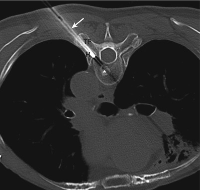

Fig. 22.13
Thoracic spine. Costotransverse approach. Computed tomography scan with the patient in the prone position shows the biopsy needle (arrow) advanced in between the left ninth rib (R) and the transverse process (TP) for biopsy of a sclerotic lesion (asterisk) involving the left posterior part of the T9 vertebral body
The needle trajectory is dependent on the orientation and the thickness of the rib and transverse process. With this approach, the bony structures do not leave much room for needle angulation. The head of the rib articulates with the superior costal facet of the corresponding thoracic vertebra, which is located in posterolateral aspect of the upper half of the vertebra immediately caudal to the superior end plate. Thus, this approach allows access to lesions involving the upper part of the vertebral body. This approach allows access to lesions involving posterior or posterolateral parts of the vertebral body on the ipsilateral side (Fig. 22.13) and also to lesions involving the anterior part of the ipsilateral pedicle (Fig. 22.10b). However, lesions involving the ipsilateral anterior or anterolateral portion of the vertebral body cannot be reached with this approach. However, this approach allows access to a much larger area of the vertebral body, including the anterior half, on the side contralateral to the needle insertion (Fig. 22.14). This approach can also be used to access the intervertebral disc one level above the level of the corresponding thoracic vertebra.
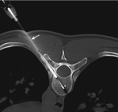

Fig. 22.14
Thoracic spine. Costotransverse approach. Computed tomography scan with the patient in the prone position shows the biopsy needle (arrow) advanced in between the left tenth rib (R) and the transverse process (TP) for biopsy of a lytic lesion (asterisk) involving the right anterior part of the T10 vertebral body
With this approach, the bony structures (namely, the transverse process and the rib) keep the biopsy needle away from the lung, pleura, and the exiting nerve roots. The presence of rib anterior to the needle path prevents inadvertent pleural transgression and prevents the needle from sliding forward along the lateral cortex of the vertebral body. The transverse process prevents passage of the needle into the spinal canal. Damage to the costotransverse articulation remains a theoretical possibility with this approach.
Stay updated, free articles. Join our Telegram channel

Full access? Get Clinical Tree


