ROLE OF RADIATION THERAPY FOR BREAST CANCER
Radiation therapy (RT) plays an important role in the management of patients with breast cancer. In patients who have undergone mastectomy for a large primary lesion or who have positive axillary nodes, postmastectomy RT (PMRT) significantly improves locoregional control and survival.
1,
2,
3 Following breast-conserving surgery, breast RT improves local control and overall survival.
4,
5,
6 The survival rate with lumpectomy and breast RT is equal to that of mastectomy,
7,
8,
9 and breast-conserving therapy is recommended by the National Cancer Institute as the treatment of choice for most women with early-stage invasive breast cancer.
8,
9,
10
GENERAL IMPORTANCE OF SETUP ACCURACY
The quality and therapeutic ratio of RT for breast cancer can be degraded if the patients are not setup accurately. Inaccurate setup can lead to underdosage of target tissues and/or increased incidental irradiation of normal tissues, either of which can reduce the therapeutic ratio of RT. For example, a substantial body of evidence suggests that RT for breast cancer (particularly using older techniques) can cause cardiac morbidity.
11,
12Older RT methods often exposed the coronary arteries, pericardium, and myocardium to significant doses of radiation, particularly in patients receiving left-sided irradiation.
13 To minimize the potential cardiotoxic effects of RT, RT techniques were modified to reduce exposure to the heart. For an example, the use of an anterior
photon field to treat both the supraclavicular and internal mammary nodes (IMNs) (the so-called “hockey stick” field) was largely abandoned.
14 Current approaches to treat the IMNs include the use of an anterior electron (with or without photon) beam to minimize exit dose to the heart. Alternatively, one can eliminate the problem of exit dose all together by including the IMNs within the tangential fields used to treat the breast/chest wall
15 and by reducing the target tissues to include only the superiorly-placed internal mammary nodal basins.
16 In addition, newer techniques in target definition (e.g., partial breast irradiation), target localization (e.g., computed tomography [CT]-based planning), dosimetric planning, and treatment delivery (e.g., intensity-modulated RT [IMRT] and respiratory control)
17,
18 may further improve the therapeutic ratio.
Conventional RT included relatively wide treatment margins and dose distributions that were not necessarily conformal. The newer approaches (e.g., partial breast, three-dimensional [3D], and IMRT) generally result in more conformal 3D dose distributions, often with rapid dose gradients toward adjacent normal tissues. The use of these newer approaches increases the need for accurate patient setup due to the high dose gradients. In this regard, very conformal dose distributions may be considered to be
more sensitive to setup errors than conventional RT. In recognition of the limitations of daily setup accuracy, it is customary to define a planning target volume (PTV) with a margin around the clinical target volume (CTV) that includes microscopic diseases to account for interfraction and intrafraction motion.
19,
20,
21Several investigators have studied the potential dosimetric/clinical impact of setup variations (
Table 12.1). Using plans based on traditional tangential fields, Das et al.
22 and Baroni et al.
23 computed that there would be only modest dosimetric consequences for the target for interfraction variations of up to 1.0 cm. In patients receiving left-sided breast tangents, Evans et al.
24 noted that the incidence of RT-associated cardiac perfusion defects was greater in patients whose tangential fields were systematically “setup” too deep. This finding was only seen in the patients whose RT beams were designed such that the deep RT field edge was immediately adjacent to the heart (i.e., if they had a “fragile plan,” with a very rapid dose gradient at the edge of the heart). Therefore, accurate setup is particularly important in patients with a tight margin on critical normal tissues. It is important for the physician to understand the expected magnitude of setup variations because this may impact upon the selected PTV margins. Obviously, the extent of margin impacts the volume of normal tissue irradiated.
25 Setup accuracy may be more important in patients undergoing accelerated partial breast irradiation (APBI) with external beams compared with patients receiving conventional whole-breast tangent fields because, with the former, the treatment margins are smaller, the number of fractions is fewer, and the dose per fraction is higher. Conversely, depending on the location of the tumor bed, the therapeutic dose volume may be closer to the heart in patients receiving conventional tangents compared with those receiving APBI.
IMAGING TECHNIQUES FOR BREAST IMAGE-GUIDED RADIATION THERAPY
Position verification has traditionally started with alignment of the patient on the treatment couch based on room lasers and “setup” marks on the skin/immobilization cradles. However, such external marks may not always accurately represent the internal target. Image guidance may increase the accuracy of patient setup. Several image-based verification methods are described.
MEGAVOLTAGE PORTAL IMAGING
Portal imaging using the treatment megavoltage (MV) beam is the most common positioning verification method.
30,
31 Portal images generated using film/screen system, computed radiography (CR), or electronic portal imaging device (EPID) provide information regarding the treatment beam location relative to internal anatomy. Portal images can be compared to reference images either obtained from a simulator by film/CR device or from digitally reconstructed radiography (DRR) calculated from planning CT. In general, MV portal imaging uses a double-exposure technique—one exposure of a shaped treatment beam with a block or multileaf collimator (MLC) and another exposure with an open field. This technique provides beam aperture information superimposed on the patient anatomy. Therefore, isocenter and beam aperture with respect to patient anatomy can be verified.
Film
Film imaging provides excellent resolution and a large field of patient anatomy. However, there are some disadvantages; it requires a film development process and therefore is generally used for offline verification. To provide geometric scale, a dotted tray (physical graticule) should be attached to the head of a linear accelerator; thus, film-based portal imaging requires extra time to allow a therapist for entering into the room between imaging and treatment delivery. Films take a physical space for storage and are not reusable. The usual delivered dose from film-based port imaging is approximately 10 cGy because one exposure requires 2 to 4 MU and a double-exposure technique is used.
32
Computed Radiography
The CR imaging system includes some of the disadvantages of the hardcopy film imaging system. CR imaging does not require a processor with wet chemical and a physical storage space. In addition, CR plates are reuseable after scanning.
33 Because CR images are digitally processed, an imaging processing method can be applied to enhance the display contrast.
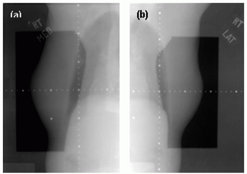
Figure 12.1 shows CR images of the right breast medial and lateral tangential fields. These images used 2 MU for the planned field and 1 MU for the opened field for the double exposure. Just like film imaging system, CR uses the double-exposure technique to verify positioning and treatment beam. The same amount of monitor units, or less, is required, and a dotted tray should be used for scaling. CR also needs time for scanning process, so it is typically used for offline verification.
Electronic Portal Imaging Device
The EPID system is capable of acquiring/viewing port images in real time with a lower dose to a patient than film or CR images. This system allows for immediate review by clinical staff to verify patient position, which then can be corrected online prior to treatment. Port images using EPID also use the double-exposure technique, and each exposure requires 1 to 2 MU and thus approximately 2 to 8 cGy to patients, which is less
than film or CR systems.
31 Another advantage of EPID over conventional film is its speed. A digital image can be acquired in a few seconds and displayed on a monitor in real time. The EPID system recognizes physical position of the detector relative to the isocenter; a digital graticule is overlaid on an image, providing position and scale information. In addition to the basic image acquisition for positioning verification, EPID is capable of acquiring continuous images, called cine images. Cine images visualize patient motion throughout the beam-on treatment time at a rate of approximately 1 image per second. This cine imaging technique allows for verification of intrafraction motion during treatment.
34 However, the field of view with EPID is often limited to approximately 20 × 30 cm
2 due to the detector size. For a large patient, a whole tangential field might not be acquired within one image field.
KILOVOLTAGE IMAGING
Kilovoltage (kV) imaging affords some potential advantages over MV imaging, including improved soft tissue contrast, a lower radiation dose needed to generate images, and image quality close to the simulation images for facilitating comparisons.
33 Gantry-mounted kV imaging systems use a kV x-ray beam to provide better image quality for patient positioning verification than MV imaging systems.
35,
36,
37,
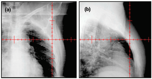
38 An x-ray tube and an a-Si flat-panel detector are mounted to the gantry orthogonally to the electronic portal imager. These kV x-ray imaging systems provide fluoroscopic and radiographic modes. Radiographic mode is useful to verify isocenter and patient positioning, whereas fluoroscopic mode enables monitoring of breathing motion or organ motion. Current kV imaging systems do not provide images of the treatment aperture. Rather, they provide only “open images” (
Fig. 12.2). A major advantage of kV over MV imaging is the dose; kV doses are approximately 100 times smaller than MV doses.
36
CONE BEAM COMPUTED TOMOGRAPHY
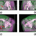
The three-dimensional images provide additional anatomic information that may improve setup accuracy. Cone beam CT (CBCT) images are reconstructed from multiple kV or MV projection images acquired during a full gantry rotation.
39,
40,
41 CBCT can then be registered with the planning CT to assess online setup accuracy. Unlike two-dimensional (2D) MV and KV images, CBCT provides full 3D information, including the external body contour and internal soft tissues (e.g., heart, lung, and postlumpectomy seroma). Therefore, setup variations due to translations, rotations, and even deformation can be considered.
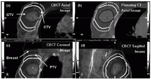
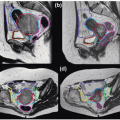
Figure 12.3 shows a representative CBCT and a corresponding planning CT.
29,
42 CBCT renders patients’ anatomy in 3D but incurs a relatively large dose (3 to 11 cGy)
36,
43 and long image acquisition/processing time (2 to 5 minutes) and requires a large clearance for full gantry rotation. Effective dose reduction techniques
44,
45,
46 are being developed to improve the procedure.
DIGITAL TOMOSYNTHESIS
Digital tomosynthesis (DTS)
47,
48 is a method for reconstructing 3D planar images from cone beam x-ray projection data acquired with limited source angles (e.g., 40 degrees). Because DTS images primarily reconstruct a specific plane of tissue, rather than projecting 3D data onto a 2D image (as is done with kV or MV film, CR, or EPID imaging), DTS may provide more accurate data for localization. Compared to CBCT, DTS requires less of a scanning angle, and hence, the concerns related to dose, clearance, and time are similarly reduced. The shorter scan time is more conducive for imaging during breath-hold compared with a CBCT. Clinically
reasonable DTS images can be acquired during a 10-second breath-hold acquisition, making breath-hold DTS an effective alternative to CBCT for 3D thoracic or abdominal image guidance.
33,
47 Localization can be assessed by comparing DTS images obtained on the treatment unit to reference DTS images computed from planning CT data. Reference DTS images are reconstructed from simulated cone beam projections through a planning CT image volume so that the onboard DTS images are compared to corresponding reference images. DTS still requires some gantry rotation, and thus, the clearance issue is not completely eliminated. The quality of DTS images is variable, depending on the degree of tissue density variation in any given plane. With the limited angle scanning (e.g., 40 degrees), objects blur in plane-toplane direction, possibly causing inaccurate positioning in the direction normal to the plane. Furthermore, it may be cumbersome for the physician to review multiple DTS images. The projection of 3D data onto a 2D image (as is done with film and EPID) is an efficient way for the physician to view anatomic information from many planes.
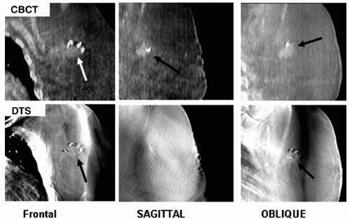
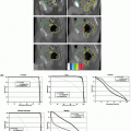
Figure 12.4 shows CBCT and DTS images for comparison.
49
SURFACE MONITORING (RENDERING) USING AN OPTICAL CAMERA
The 3D surface data of the breast are obtained from a 3D optical camera that is rigidly mounted on the ceiling of the treatment room. This technique uses visible light, and thus, there is no ionizing radiation to the patient. The camera visualizes the skin markers overlaid on the 3D surface image, which allows for determination of the isocenter position and the beam angles in the breast tangential fields automatically. Thus, this system enables capturing of daily 3D surface images of the target, adjusting of the treatment beams to accommodate the changes in the target shape and volume, and correcting of the patient position by shifting the couch. The major disadvantage of the video system is that images do not contain information of the internal structures (
Table 12.2).
50,
51,
52,
53
APPLICATION OF IMAGE-GUIDED RADIATION THERAPY IN RADIATION THERAPY FOR BREAST CANCER
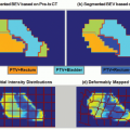
Techniques for image-guided RT (IGRT) are adapted to improve setup accuracy in various ways, including general patient positioning, target localization, presence of lung or heart, interfractional/intrafractional motion, and so on. The utility of IGRT for patients with breast cancer can be inferred by studies that have addressed the degree of inter- and intrafraction motion (
Table 12.3). The parameters described previously and in
Figure 12.5 are commonly used to analyze the setup variation using imaging modalities. These parameters appear clearly in the projection images taken by conventional films, CR, or EPID.
The average interfraction setup variations assessed in the 2D radiographic images range from 2 to 6 mm,
28,
34,
60,
61,
62,
63,
64,
65,
66,
67,
68 which could have been overlooked without IGRT. 2D IGRT can reduce these variations to the range of approximately 3 mm, especially if immobilization systems are used as well.
60,
62,
67 3D IGRT (e.g., CBCT or surface rendering) can further reduce these uncertainties to approximately 2 mm in one direction or 6 mm in vector.
29,
53 2D IGRT appears to provide an efficient manner to assess the location of the lung, heart, and localization clips. The additional accuracy provided by the 3D IGRT is often modest unless soft tissue or tomographic information is desired. Images (e.g., EPID) taken before and after, or during, quantify the degree of intrafraction motion.
34,
50,
61,
63,
64,
65,
69 The noted average degree of intrafractional motion usually ranges from 0 to 3 mm in each of the primary directions. Variations in the cranial-caudal direction are generally larger than in the other directions. Surface
imaging techniques suggest similar results with intrafraction motions of approximately 2 mm in the cranial-caudal direction.
50,
53 The need for imaging before or during RT is thus a clinical decision based on the conformality of the therapeutic dose volume to the target tissues, the risks to adjacent normal tissues, and patient-specific assessments of motion.
The utility of IGRT may increase as treatment delivery techniques become more complex. Conventional RT for breast cancer includes two tangential fields, often shaped with a block or MLC to shield the lung and heart. This conventional treatment includes large margins, and the resulting dose distributions are relatively insensitive to the setup errors. For example, misalignment of the isocenter by 1 cm results in only modest (2%) effects on the dose distribution.
22 The newer approaches (e.g., partial breast RT and IMRT) typically provide a more rapid dose gradient close to the main targeted areas, and thus, there may be increased need for accurate patient setups. IGRT may also play an increased role for patients treated in the prone or decubital positions, because these may be more challenging to setup in a reproducible fashion.
Table 12.4 illustrates some interactions between treatment technique and IGRT.
CHALLENGES FOR THE FUTURE
Current radiation techniques for patients with breast cancer provide excellent results. Local control and normal tissue reactions are generally acceptable. One might argue that possibilities for dramatic improvements are limited. This may make it difficult to detect improvements afforded by IGRT. Furthermore, because IGRT may increase the complexity and cost of RT, it may become challenging to justify the extra expense/effort. Nevertheless, conventional radiation fields are relatively large in part due to the use of a relatively large PTV to accommodate setup uncertainty, and a clinically meaningful number of patients do develop acute and/or late normal tissue reactions. Therefore, because improved patient setup (e.g., through IGRT) may lead to improvements in the therapeutic ratio, it is reasonable to further study the utility of IGRT for patients with breast cancer. As we are implementing various IGRT techniques for breast radiation treatment, challenges appear for the current and future applications. This section discusses some of challenges discovered by researchers who have been investigating improvement for breast RT.
MOTION AND DEFORMATION
Many of the IGRT methods described earlier are best suited to address interfraction variations in setup. Intrafraction motion (e.g., respiration-induced tumor motion) is also a potential concern. However, the available data suggest that intrafraction motion is typically of smaller magnitude than interfraction motion. Kron et al.
34 used EPID to monitor intrafraction motion in patients with breast cancer undergoing conventional tangential RT. Movements of the lung/chest wall interface and the edges of the breast were assessed. The largest variability was 1.3 mm detected in the cranial-caudal direction. The lung/chest wall interface movement was only 1.1 mm. For patients receiving tangents, Chui et al.
83 computed that intrafraction motion essentially broadened the penumbra at the posterior field edge. The dose in the rest of the treatment volume was not significantly affected. The same effects were observed for both IMRT and conventional treatment techniques. This is not surprising because conventional tangents include “flash” round the anterior, superior, and inferior surfaces of the breast contour and movements of these boundaries will not typically affect the dose delivered to most of the breast. Thus, it appears that intrafraction motion is not a major concern for most patients receiving breast/chest wall tangential irradiation.