Image-guided Adaptive Radiation Therapy and Practical Perspectives
Image-guided Adaptive Radiation Therapy and Practical Perspectives
Lei Xing
Louis Lee
Robert Timmerman
With the development of intensity-modulated radiation therapy (IMRT) in the 1990s, radiation therapy (RT) entered a new era. By optimally modulating the incident beam fluences, exquisite dose distribution can be planned and delivered. IMRT offers a valuable tool for dose escalation and/or radiation toxicity reduction and shows significant potential to improve therapeutic ratio.1, 2, 3, 4, 5 In reality, however, a highly conformal dose distribution is not enough; the dose should also be delivered to the right place at the right time. Indeed, IMRT alone does not completely solve the problem of beam targeting in RT. The patient anatomy changes from day to day (interfractional organ motion) and even during the dose delivery process (intrafractional organ motion) due to patient setup inaccuracy and voluntary or involuntary physiologic processes of the patient. For example, organ motion happens involuntarily for structures that are part of or adjacent to the digestive or urinary systems. Changes in the patient’s condition, such as weight gain or loss, can also affect the relative position of the clinical target volume (CTV). The advantage of IMRT can only be fully exploited with effective means of eliminating the uncertainties caused by these factors.
The adverse effects of inter- and intrafractional organ motions have been studied extensively in the literature.6,7 Because of the anatomy change, the actual received dose distribution of the patient may well differ from the planned one. The two scenarios of relevance are insufficient dose coverage of the tumor volume and overdosage of normal tissues. To account for the uncertainties caused by patient setup inaccuracy and organ motion and avoid potential geographic miss of the tumor target, a population-based safety margin encompassing the tumor target is usually introduced (see Chapter 3 for details). Similar strategy applies to the sensitive organs to ensure the sparing of the structures. The margins are often too large for some patients or too small for others and significantly compromise the treatment outcome. Clinically, the patient setup relies primarily on information from the simulation and planning. The same treatment plan and setup digitally reconstructed radiographs (DRRs) are usually used throughout the whole course of treatment, with effort being focused on reproducing the patient’s geometry at the simulation stage using translations (and occasionally rotations). This procedure is fundamentally deficient in that it attempts to tackle a multidimensional internal anatomy change by only a few degrees of freedom (i.e., translation and possibly rotation of the patient). The unreliable correspondence between the anatomies at the times of simulation and the actual treatments represents one of the weakest links in the quality chain of the current RT practice.
Effective image guidance and seamless integration of the imaging data into daily dose delivery process are the keys to circumvent the various uncertainties mentioned above. Although imaging has always been a part of the RT process, its role has never been as important as it is today. A general trend in image-guided RT (IGRT) is to image the patient at a frequency commeasuring with or finer than the time scale of the anatomy changes and to use the data as an online/offline feedback to better direct the subsequent treatment. Briefly, adaptive RT (ART) is about how to attain the feedback information and how to compensate the anatomic or even biologic changes by effectively modifying the patient’s treatment plan upon receiving feedback data.8, 9, 10, 11, 12 An adaptive approach breaks the conventional sequential procedure of RT simulation, treatment planning, and dose delivery and is thus dramatically different from today’s “one plan for all fractions” approach.
In reality, due to the difference in the nature and characteristics of organ motion in different disease sites, the requirement for image guidance and plan adaptation may well be different. For a site where intrafractional organ motion is less of a problem, such as the brain or head and neck (HN), a daily imaging prior to the patient’s fractionated treatment seems to be adequate to capture the patient setup error and interfractional anatomy change. However, for a disease site where intrafractional organ motion exists, such as lung and liver cancers, an ideal solution should consist of not only pretreatment three-dimensional (3D) or four-dimensional (4D) imaging, but also frequent imaging with duration shorter than that of anatomy change caused by respiration motion.13, 14, 15, 16, 17 Real-time image feedback of anatomic information is essential for us to take advantage of the latest gating and any other organ motion-harmonized beam delivery techniques.18, 19, 20, 21, 22 In a broad sense, all of these scenarios are examples of image-guided adaptive RT (IGART) because of the involvement of feedback data in subsequent dose delivery. To be specific, in this chapter, we will focus our discussion on a special type of IGART designed to tackle the problem caused by patient setup inaccuracy and interfractional organ motion. An important feature of this type of IGART is the use of pretreatment feedback for subsequent treatment decision making. Technical solutions developed to deal with intrafractional organ motion, such as respiratory gating and motion-harmonized RT, are described in other related chapters of this book.
EVOLUTION OF ADAPTIVE RADIATION THERAPY
Due to the limitations in computation, imaging, and delivery techniques, the efforts in improving RT have been along two major directions. The first is to come up with better immobilization devices to reproduce the patient setup, and the second is to develop a better target localization strategy to reduce the planning target volume (PTV) margin. The development of the stereotactic radiosurgery frame and stereotactic body frame represent examples of the first attempt. Although this approach is effective for some disease sites, such as the brain, the use of an immobilization device is ultimately limited by the poor correlation between the external or bony landmarks and the internal anatomy in many disease sites. The concept of adaptive therapy was brought into the radiation oncology discipline by the group at the William Beaumont Hospital in 1997,8 but the implications and implementation of ART have evolved dramatically over the years. Adaptive therapy is a generic term for a therapeutic process in which the treatment strategy is updated from time to time upon receiving updated system information. Not surprisingly, the level of improvement of a specific adaptive approach depends critically on the form and quality of the feedback. It is important to emphasize that the content of ART is a moving subject and becomes more sophisticated with the advancement of the on-treatment feedback techniques. In the 1990s, the electronic portal image device (EPID) and stand-alone computed tomography (CT) scanner were the only technologies available for acquiring feedback data during the course of a patient’s treatment, and the focus was on adaptively defining the margin in delineating the tumor PTV.8 The early offline or online CT-based adaptive strategy23,24 aims to partially compensate for organ motion by carrying out multiple CT scans in consecutive days in the first week of treatment. The image data are then used to construct a patient-specific PTV model from the composite CTV with inclusion of statistical variations of the observed motions. However, the approach relies on establishing a statistical ensemble of all possible setup scenarios under a strong assumption that a limited number of offline CT scans can adequately describe the inherently complex and often unpredictable interfractional organ motion.
Imaging has been a critical element that drives the evolution of IGART. Many methods are developed to meet the increasing clinical need of better “seeing” the tumor and soft tissue structures. For convenience, the major imaging and target localization techniques and their characteristics are summarized in Table 2.1. In principle, all of the techniques listed in the table are useful in providing feedback information for adaptive modification of a patient’s treatment plan. However, it seems to be fair to state that clinically meaningful ART starts with the introduction of onboard volumetric imaging in radiation oncology clinics. In essence, the volumetric imaging provides the patient’s on-treatment geometric model upon which adaptive replanning can be performed to cater for any anatomic change, not only concerning the tumor target but also the involved sensitive structures. A flowchart of modern adaptive therapy is shown in Figure 2.1 together with the conventional treatment process.
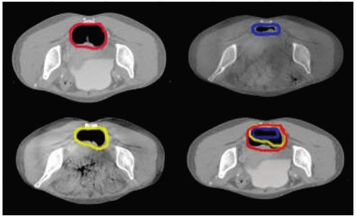
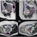
To emphasize the potential implication of volumetric imaging in ART, Lee et al.25 have recently analyzed the routine cone beam CT (CBCT) images acquired during the RT course for eight rectal cancer patients. Clinically, rectal volume motion and deformation can cause significant uncertainties pertaining to the adequacy of actual dose delivered to the CTV, which has been a major obstacle in the implementation of IMRT in rectal cancer. Onboard CBCT is valuable for assessing rectal volume and dosimetric changes during a course of RT. Figure 2.2 shows the planning CT (pCT) and three CBCT images of a rectal cancer patient acquired at the beginning of every week for the first 3 weeks. Significant target volume motion and deformation were observed. It was found that the ranges of deformation changes in the lateral direction at the superior, middle, and inferior slices were 0 to 2.54, 0 to 2.60, and 0 to 1.98 cm, respectively. Similarly, the ranges in the anterior-posterior direction were 0 to 2.44, 0 to 3.77, and 0.07 to 2.53 cm, respectively. Ranges in the distances of the geometric centers of the rectal contours between the paired CTs at the three slices were found to be 0 to 2.24, 0 to 2.07, and 0 to 2.07 cm, respectively. To cope with such a broad range of tumor motion by a margin-based approach or any other nonvolumetric imaging technique is clearly difficult without significantly compromising the normal tissues. Volumetric CBCT imaging provides a basis for us to model the multidimensional organ motion and to adaptively modify the treatment plan to compensate any interfractional anatomy change of the target as well as the sensitive structures.
KEY COMPONENTS OF MODERN ADAPTIVE RADIATION THERAPY
Currently, RT simulation, treatment planning, and dose delivery are done sequentially. With the emergence of the onboard volumetric imaging device, the implication of ART has dramatically changed. The volumetric feedback data make it possible, for the first time, to construct the patient’s on-treatment geometric model. Thus, one can adaptively modify not only the PTV margin, but also the spatial dose distribution to best accommodate any change in patient anatomy as well as the dosimetric deviation from the prescription incurred in previous fractions. IGART promises to eliminate or minimize the adverse influence of interfractional geometric or even biologic changes in a fundamental fashion. In the last few years, much research has been devoted to the subject. Also notably, various vendors are making significant efforts along these line (see Chapter 19). There are strong indications that IGART will likely become practical and affordable through continuing developments and automation of the various steps involved.
Different from the current practice, IGART does not insist on reproducing the patient’s simulation geometry. Instead, it compensates the anatomic changes through optimal adjustment of incident beam parameters. Depending on the specifics of the clinical problem and implementation, the adaptive replanning can be done offline or online. In this approach, the role of simulation geometry and treatment plan is different from that in current practice. A treatment plan provides an overall estimate of the treatment specifics and dosimetry and serves as a reference and starting point for subsequent replanning. In a broad sense, IGART has already been in the clinics for years. In conventional 3D conformal RT (CRT), for example, it is not uncommon for a physician to modify a beam portal under the guidance of on-treatment portal films/images, which is a preliminary version of ART. With technical advancements, particularly in computer and network technology and optimization algorithms, online IGART is becoming increasingly feasible and may likely become a “standard practice” in the near future. Ultimately, whether or not IGART can improve patient survival and reduce side effects can only be established through extensive clinical trials. However, it is important to note that there are already some reports showing the impact of image guidance with respect to improving actual clinical outcomes.26, 27, 28
TABLE 2.1 Summary of Major Imaging and Feedback Techniques for IGRT and IGART
Technology
Major Applications
Advantages
Disadvantages
Availability
Stereoscopic kV x-ray imaging
Patient setup and pretreatment target localization
Monitoring of intrafraction organ motion
Relative low cost
Good soft tissue contrast
Excessive imaging dose
Limited x-ray sampling rate
Blocked views at certain gantry angles, restricting its application in arc therapy guidance
CyberKnife from Accuray Inc.
ExacTrac from BrainLab AG
Combined MV and onboard kV imaging
Patient setup and pretreatment target localization
Real-time tracking of intrafractional target motion
Low imaging dose because only one kV imager is needed
Minimal modification in hardware and workflow
Applicable to provide real-time guidance in both fixed-gantry and arc therapy
Low soft tissue contrast in MV image of inline direction
Limited field of view in MV image for certain IMRT segments and the need for software-based estimation in this particular situation
Research prototype from Stanford University
Onboard cone beam CT (CBCT)
Pretreatment volumetric imaging for patient setup and adaptive replanning
Pretreatment projection (planar) imaging for patient setup
Availability of on-treatment 3D and 4D image information
Opportunity for online replanning and adaptive radiation therapy
Possibility of real-time kV projection imaging
Excessive radiation dose when used routinely
Capital cost
Synergy from Elekta AB
Trilogy from Varian Medical Systems
In-room CT
Pretreatment volumetric imaging for patient setup and adaptive replanning
Availability of on-treatment 3D and 4D image information
Opportunity for online replanning and adaptive radiation therapy
CT images of diagnostic quality
Excessive radiation dose when used routinely
No real-time organ motion information available
Assumption of a fixed relationship between the isocenters of the two otherwise independent systems (CT and linac)
Capital cost
Requirement for enlarged treatment room
Primatom (CT-on-Rails) from Siemens Oncology Solutions
CT-in-room from Varian Medical Systems and GE Medical Systems
MV helical or CBCT (MVCT)
Pretreatment volumetric imaging for patient setup and adaptive replanning
Pretreatment MV projection imaging for patient setup
Availability of on-treatment 3D image information
Opportunity for online replanning and adaptive radiation therapy
Same isocenter for the MVCT and linac
MVCT images free from high-density artifacts
Excessive radiation dose when used routinely (a few times more than that of kV CBCT imaging)
No real-time organ motion information available
Soft tissue discrimination inferior to kVCT
Hi-Art System from TomoTherapy Inc.
MVision from Siemens Oncology Solutions
Electromagnetic localization using transponders
Pretreatment target localization
On-treatment real-time target tracking
No ionizing radiation
High accuracy
Provide temporospatial information of the target
High capital cost
No spatial information of nearby sensitive organs
Severe MRI artifacts
Limited to a few disease sites
Calypso 4D Localization System from Calypso Medical Technologies
Transabdominal ultrasound
Pretreatment localization
No ionizing radiation
Noninvasive approach; no fiducials needed
Availability of spatial information of nearby sensitive organs
Relative low cost
Interuser variability
No real-time tracking of the target
Limited to a few disease sites
BATCAM from Best Nomos
SonArray from Varian Medical Systems
Clarity from Resonant Medical
Optical surface imaging
Pretreatment patient localization for certain types of diseases
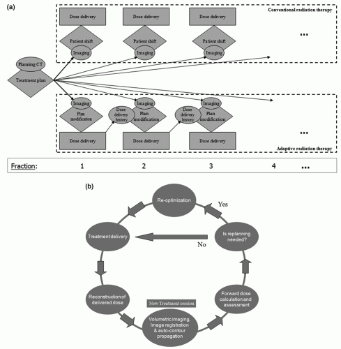
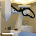
Figure 2.1. a: Conventional radiation therapy process (top) and image-guided adaptive radiation therapy process (bottom). b: Data flow of volumetric image-guided adaptive radiation therapy treatment scheme at a treatment session.
Technically, to establish the new paradigm of IGART shown in Figure 2.1, a number of enabling tools that are absent in current RT practice must be in place. These include (a) an optimized volumetric imaging protocol; (b) a reliable deformable registration technique for the calculation of cumulative dose; (c) an efficient CBCT image segmentation technique; (d) a CBCT-based dose calculation and method of reconstructing the delivered dose distribution; and (e) a closed-loop framework for ART dose optimization. These issues are discussed in the following sections in some details.
Figure 2.2. Planning computed tomography (pCT) and three cone beam computed tomography (CBCT) images of a rectal cancer patient acquired during the course of radiation therapy. The upper left image is pCT, and the remaining three images are CBCT images acquired at the beginning of the first (upper right), second (lower left), and third weeks (lower right) of the treatment course. The overlay of the rectum target at different time points is shown on the lower right image as well. (From Lee P, Xing L, Pawlicki P, et al. Image-guided radiation therapy for rectal cancer using cone beam CT. Int J Radiat Oncol Biol Phys. 2006;66:S27, with permission.)
Onboard Volumetric Computed Tomography Imaging
Both kilovoltage (kV) and megavoltage (MV) flat-panel imagers integrated with a linear accelerator (linac) have become available for therapy guidance. The former typically consists of a kV source and amorphous silicon (aSi) flat-panel detector combination mounted on the drum of a linac,29 with the kV imaging axis orthogonal to that of the MV therapy beam. The majority of linacs purchased in the past few years are equipped with the onboard volumetric imaging capability. The system provides online 3D or even 4D30, 31, 32, 33 patient anatomy data that are valuable for patient setup and, more importantly, adaptive replanning.12,23,34, 35, 36, 37 Presently, the system is primarily used for guiding the patient setup through the use of rigid 3D-3D registration technique.38, 39, 40, 41 Although the CBCT images can clearly reveal setup error and readily detect rotational errors, the rigid registration-based patient setup procedure falls short in the presence of organ deformation or relative displacement of the involved organs (e.g., movement of the prostate gland relative to the regional lymph nodes or pelvic bones). As mentioned earlier, RT in the presence of organ deformation is a multidimensional problem that cannot be solved completely by translation and rotation of the patient. The true value of onboard volumetric imaging lies in its ability to provide the patient’s on-treatment geometric model for dose reconstruction and adaptive replanning.
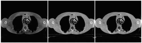
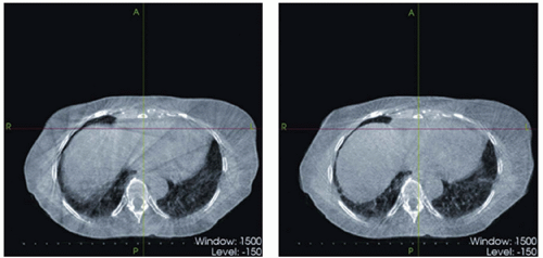
The quality of current CBCT is still far from optimal due to the high scatter-to-primary ratio (SPR) caused by the increased exposed volume in the cone beam geometry and, in the case of the thorax and upper abdomen, intrascan organ motion. Excessive radiation dose is also of concern when a patient is imaged repeatedly during a course of RT.42,43 It has been reported that using typical imaging parameters, each CBCT scan for daily patient setup results in a skin dose of approximately 3 cGy, and the dose received inside the body can be as high as 10 cGy.43 CBCT imaging is currently an active area of research. Various methods of scatter reduction and motion artifacts removal are being investigated. Briefly, there are two major types of scatter removal techniques.44 The first performs scatter suppression during the acquisition of projection data based on the incident angle difference of the primary photons and the scatter photons (e.g., the antiscatter grid method and the air gap method).45,46 The limited efficiency is a major factor limiting the practical application of the approach.46,47 Another type of scatter removal technique is through proper modeling of the scatter photons and postprocessing of the scatter-contaminated projection images.48 Along this line, Zhu et al.44,49 have proposed a patient setup and scatter removal protocol for RT applications. In their approach, a sheet of lead strips is inserted between the x-ray source and the patient to extract the patient-specific scatter profile, which is then used to correct the subsequent CBCT scans with consideration of potential patient setup variation. They noticed that model-based scatter reduction alone does not always warrant high-quality CBCT images because the high-frequency scatter noise remains after a model-based correction. Thus, a scatter correction should be used together with a noise suppression algorithm to achieve a satisfactory image. As the scatter correction techniques become more successful, this issue becomes increasingly important. In Figure 2.3, CBCT images of an anthropomorphic phantom with and without scatter removal and noise suppression are displayed. Improvement of image quality is essential not only for better seeing the anatomy, but also for accurate dose computation and replanning (see Cone Beam Computed Tomography-Based Dose Calculation and Dose Reconstruction section later in this chapter).
Figure 2.3. Reconstructed cone beam computed tomography (CBCT) images of an anthropomorphic phantom. Left: No scatter correction and no noise suppression; noise variance in the selected region of interest (ROI) (white square): 1.010 × 10⁻⁶. Middle: Scatter correction without noise suppression; noise variance in the ROI: 1.006 × 10⁻⁵. Right: Scatter correction and noise suppression; noise variance in the ROI: 9.749 × 10⁻⁷. (From Zhu L, Wang J, Xing L. Noise suppression in scatter correction for cone-beam CT. Med Phys. 2009;36:741-752, with permission.)
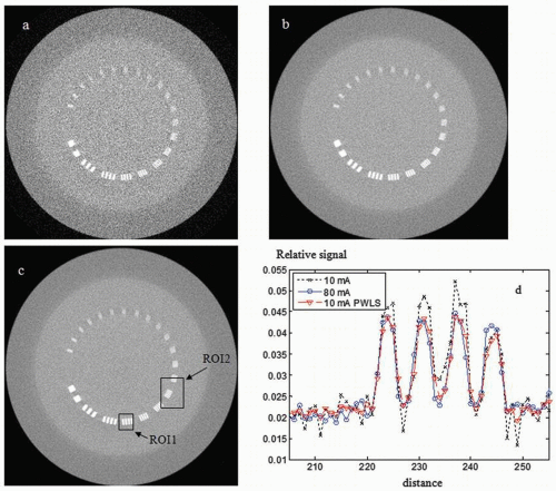
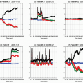
An arena for CBCT dose reduction is to image the patient with lower milliamperes and then recover the quality of the resultant images through the use of a statistical analysis-based noise removal technique.50 An iterative image reconstruction algorithm based on a penalized weighted least squares (PWLS) principle has been developed to incorporate the noise spectrum into the reconstruction calculation and to effectively suppress the adverse effect of lowering the milliamperes.50 The PWLS consists of two terms: a weighted least squares (WLS) term that models the measurement data and a penalty term that encourages image smoothness of reconstructed images. The WLS criterion is formulated in such a way that the measured projection data with a lower contrast-to-noise ratio (CNR) will contribute less to the estimation of attenuation map. The CBCT images reconstructed by minimizing the PWLS objective function using the Gauss-Seidel updating strategy show marked improvement in image quality. Figure 2.4 shows slices of the phantom images that contain several bar patterns with different widths and spacing. The image reconstructed from the PWLS processed sinogram (10 mA) is comparable to that obtained with 80-mA protocol in terms of detectability of the bars (see the region of interest [ROI] 2 in Fig. 2.4C). To show the difference between parts A, B, and C of Figure 2.4, horizontal profiles along the central bar patterns are plotted (ROI1 of Fig. 2.4C) in Figure 2.4D. It can be observed that the edges are well preserved.
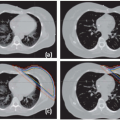
A few groups30,31,51,52 have investigated strategies to acquire 4D CBCT images based on phase-binning of the CBCT projection data. The phase-binned projections are reconstructed using either the conventional Feldkamp algorithm or a more advanced method to yield 4D CBCT images. Li et al.52 studied several factors that are important to the clinical implementation of the technique, such as the scanning time, number of projections, and radiation dose, and proposed an optimal 4D CBCT acquisition protocol for an individual breathing pattern. Figure 2.5 shows a 4D CBCT image (one phase) of a liver cancer patient with reduced breathing artifacts compared to its 3D counterpart. Li et al.53 also investigated a motion compensation method for slowrotating CBCT scan by incorporating into image reconstruction a patient-specific motion model, which is derived from 4D treatment pCT images of the same patient via deformable registration. It has been demonstrated that the algorithm can reduce the motion artifacts locally and restore the tumor size and shape, which may thereby improve the accuracy of target localization and patient positioning. 4D CBCT is important for future 4D ART because it allows one to derive the patient’s on-treatment 4D model.
Deformable Image Registration
Image registration is to establish a voxel-to-voxel correspondence between two input images to be registered: a fixed image and a floating image, described by their intensity distributions Ia(x) and Ib(x), respectively. Mathematically, this is to find the transformation matrix T(x,x′) that maps an arbitrary point x from the fixed image to the corresponding point x′ on the floating image (or vice versa). The matching of two input images is generally formulated as an optimization problem, and the best registration is obtained by iteratively comparing various possible matches until no better registration can be found. According to the nature of the transformation, the alignment can be divided into rigid or deformable registration. A rigid transformation has six degrees of freedom: three rotational plus three translational variables. The determination of the transformation matrix for a deformable registration, however, is much more complicated because the matrix consists of a huge number of unknowns. The problem is usually underdetermined due to the high dimensionality of transformation and even ill conditioned, which may result in instability of solutions and local optima. Clinically, the need for robust deformable registration algorithms to fuse images acquired under different conditions or with different modalities is ever increasing because of the extensive use of multimodality imaging and the emergence of new imaging methods. Applications of deformable model in IGART include, but are not limited to, (a) better tumor target definition25; (b) motion model-based image reconstruction53, 54, 55; (c) image enhancement56, 57, 58; (d) propagation of organ contours from one image set to another59, 60, 61; and (e) calculation of accumulated dose in organs experiencing deformation.12,62, 63, 64, 65
Figure 2.4. One slice of cone beam computed tomography (CBCT) images of the CatPhan 600 Phantom (The Phantom Laboratory, Salem, NC) containing several bar patterns: (a) from projection images acquired with 10-mA tube current; (b) from the sinogram acquired with 10-mA tube current that has been processed by the penalized weighted least squares (PWLS) algorithm; and (c) from projection images acquired with 80-mA tube current. d: Profiles through the central bar pattern in the images (indicated by region of interest 1 [ROI1]). (From Wang J, Li T, Liang Z, et al. Dose reduction for kilovoltage cone-beam computed tomography in radiation therapy. Phys Med Biol. 2008;53:2897-2909, with permission.)
Two central issues in deformable registration are (a) definition of the registration metric function and (b) algorithm to find the transformation that optimizes the metric function. A metric function is usually constructed based on some physical considerations and used to measure the goodness of an arbitrary association of the two images. A variety of metric measurements exist in the literature, which include, to name a few, mean square difference of intensities, normal cross correlation, entropy of the difference image, mutual information, and pattern intensity. Depending on the method used to model the deformation, the registration can usually be categorized into elastic model,66, 67, 68 viscous fluid model,69 optical flow model,70, 71, 72 finite element model (FEM, or biomechanical model),67,73 radial basis function (RBF) model such as basis spline (B-spline) model,74, 75, 76 and thin plate spline (TPS) model.77, 78, 79, 80, 81 Among them, the B-spline model is widely used for its simplicity and versatility. In this approach, the transformation coefficients T(x,x′) are obtained by optimizing the metric function with respect to the displacements of some sparsely sampled nodes. To facilitate the optimization, it is preferable that both the deformable model and the metric are differentiable.82 The selection of optimization algorithm is usually dependent on the metric function, and there is a whole armamentarium of tools available to carry out a task of metric function optimization.
Most, if not all, registration algorithms ignore the underlying tissue features but simply rely on the similarity of image intensity. Introduction of regularizations and incorporation of prior physiologic and anatomic knowledge into the problem formulation are valuable to eliminate nonphysiologic results, such as bone warping, and greatly enhance the success of deformable registration. In this case, a cost function often consists of a similarity measure and a penalty term that discourages undesirable transformations. In general, performance of registration can be improved by identifying the same anatomic structures across different subjects. Schreibmann et al.83,84 investigated a method of auto-identifying homologous control points on the two input images in a region where distinct image feature exists and used the association to facilitate image registration. The performance of this type of approach can be enhanced by more advanced algorithms with autodetection of inherent tissue features. Shen and Davatzikos85 used a concept of “attribute vector” and introduced hierarchical attribute matching mechanism for elastic registration (HAMMER). The attribute vector, which is attached to every voxel in the image, includes not only the image intensity and edge information, but also the geometric moment invariants. The scale invariance feature transformation (SIFT),86,87 in which the corresponding tissue feature is described by the local information in the neighborhood of a point of interest, represents another method that goes beyond a simple intensity-based approach. The obtained homologous SIFT tissue features can be treated as a priori knowledge for improved deformable registration calculation.88 The HAMMER and SIFT methods, along with other similar methods, are particularly valuable to model tumor growth and shrinkage and to deal with discontinuous movements at the boundaries of different anatomic structures.
Figure 2.5. Comparison of four-dimensional (4D) cone beam computed tomography (CBCT) (right, only one phase shown) and three-dimensional (3D) CBCT for a liver cancer patient. (From Li T, Xing L, McGuinness C, et al. Four-dimensional cone-beam CT using an on-board imager. Med Phys. 2006;33:3825-3833, with permission.)
Registration beyond Simple Deformable Models
Registration of pCT and CBCT images may be complicated by a number of factors. In addition to the relatively poor quality of CBCT images, there are anatomic changes that cannot be described by a conventional deformable model. For example, when there are image features that are not shared by the two input images (e.g., the variation of rectal contents due to the presence/absence of bowel gas and fecal matters), a direct application of an intensity-based registration may be problematic.88 The shear motion of the organs, such as the lungs and the liver, against the chest wall is also known as a complication factor in thoracic image registration. Weight loss or gain and tumor shrinkage or growth are additional examples that the conventional deformable registration methods may fail to consider. For these applications, more sophisticated image registration tools need to be developed.
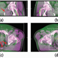
Xie et al.89 have recently reported a tissue feature-based image registration strategy with explicit inclusion of the differential motions of thoracic structures. The technique started with auto-identification of a number of corresponding points with distinct tissue features by using the SIFT method. The control point pairs were then sorted into different “colors” according to the organs they reside and used to model the involved organs individually. A TPS method was then used to register a structure characterized by control points with a given “color.” In a digital phantom test, a comparison with the conventional TPS method showed that the registration accuracy was markedly improved when the differential motions of the lung and chest wall were taken into account. On average, the registration error was reduced from 3.0 to 0.5 mm when the new method was used. A similar level of improvement was achieved for the clinical cases. Figure 2.6 presents a comparison between the results obtained using their method (top row) and the conventional TPS method (bottom row) for a lung case. It is clearly shown that the unphysical bony structure warping, which occurs in several regions in conventional TPS registration, is effectively avoided.
During the course of radiation treatment, many patients develop significant anatomic changes due to multiple factors, including shrinkage of the tumor and/or nodal masses, weight loss, and resolution of postoperative changes.90, 91, 92, 93, 94, 95 In a recent study of 13 patients with tumors or lymph nodes measuring ≥4 cm in diameter, Barker et al.90
Only gold members can continue reading. Log In or Register to continue