Errors, Margins, Localization, and Correction
Jan-Jakob Sonke
Marcel van Herk
In external-beam radiotherapy (RT), patients are treated with multiple megavoltage (MV) photon beams generated with a linear accelerator (linac). The treatment plan is generally designed based on a single computed tomography (CT) scan acquired before treatment, and the plan is delivered in several fractions on different days. This process introduces a number of inherent inaccuracies. In this chapter, we will first describe the most important sources of geometric uncertainty and ways to account for these. The aim of image-guided RT (IGRT) is to reduce geometric uncertainty. We will describe the use of advanced imaging for treatment planning, image registration, and imaging for delivery to increase the precision of RT. Finally, different styles of correction strategies to address these uncertainties will be described.
GEOMETRIC UNCERTAINTIES
SYSTEMATIC AND RANDOM ERRORS
There are many sources of uncertainty that act during preparation of RT and its delivery. Each of these uncertainties might be small in general, but the combined effect of all associated errors can be substantial and will limit the precision of treatment. Here, we define “error” as any discrepancy between planning and treatment, however small it is. In this context, errors are unavoidable, and it is through methods such as image guidance that their magnitude is limited. The expected range of errors (or uncertainty) is expressed in statistical quantities, with the standard deviation (SD) being the most important. Gross errors do not fall under this category; their occurrence should be limited through quality assurance procedures. Errors made during the treatment preparation phase will be made only once. In the absence of image-guided correction strategies, these errors will then be present during every treatment fraction. Errors made during treatment delivery of fractionated RT, however, will be made several times and are likely to be different every day. Errors that are identical for every fraction are called systematic errors, whereas errors that vary day by day are called random errors. For treatments with a limited number of fractions, however, random errors will not completely cancel out (their mean will not be zero). This gives rise to an additional systematic error, with SD being the SD of the random error divided by the number of fractions.1,2 If, however, the systematic error is estimated from all fractions, this estimate will automatically include this component. The dosimetric effect of systematic and random errors is different.3,4 Random errors blur the cumulative dose distribution,5 whereas systematic errors shift the cumulative dose distribution. Note that both random and systematic errors are stochastic; although systematic errors are only made once per patient, repeating the preparation phase would result in a different systematic error. Table 3.1 exemplifies how to estimate the parameters (systematic [μ, Σ] and random error [σ, σσ]) of the underlying probability distribution based on measured patient data. Note that an accurate estimate of (σσ), reflecting the interpatient variation in the random error, requires a lot of samples per patient,6 whereas in practice, the difference in σ between patients is so small that it cannot be detected given the limited number of measurements.
IMAGING ERRORS
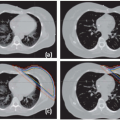
RT preparation starts with the acquisition of patient images, nowadays predominantly done in three dimensions (3D; e.g., CT, positron emission tomography [PET], magnetic resonance imaging [MRI]). Because the patient imaged during this first session might not be representative for the treatment delivery, a systematic error is introduced. In addition, the imaging process itself can introduce geometric errors. The images have finite resolution, in particular perpendicular to the slice planes, causing the partial volume effect.7 Furthermore, images can be distorted, in particular in MRI as a result of chemical shift,8 object-induced distortions,9 and imperfections of the main magnetic field.10 Also, patient motion during image acquisition, such as respiration, can distort the images (Fig. 3.1).11 Images acquired on different machines will not share the exact same origin, so setup error occurs also during imaging. Even with dedicated machines like PET-CT scanners, the origin (in terms of a point in the anatomy) of the two modalities is not intrinsically linked, and inaccuracies may be present (e.g., due to sagging of the patient table or patient motion between different components of the scan procedure). In addition, inadequate patient support may cause an awkward patient pose or shape that cannot be reproduced during treatment. Appropriate slice thickness and distance, image distortion correction algorithms, and careful calibration procedure and quality assurance are ways to minimize imaging errors.
TABLE 3.1 Example to Illustrate the Estimation Process of the Underlying Statistical Parameters of the Underlying Probability Distribution Describing the Random and Systematic Errors Based on Measurements in a Group of Patients | ||
|---|---|---|
|
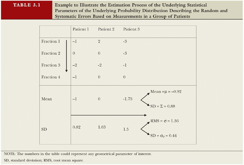
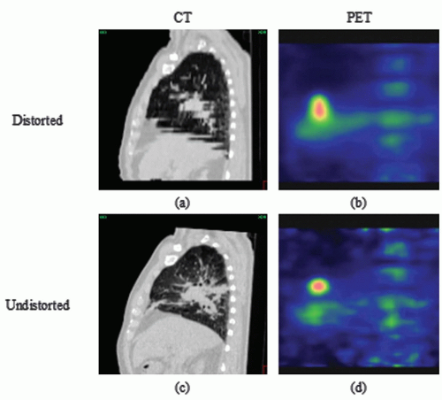 Figure 3.1. Examples of imaging errors induced by respiratory motion during image acquisition in (a) computed tomography (CT) and (b) positron emission tomography (PET). In (c and d), undistorted equivalents are shown obtained by time-resolved imaging. |
DELINEATION/TARGET DEFINITION UNCERTAINTIES
Target and organs at risk are generally defined on a planning CT scan by manual delineation. Several geometric uncertainties are involved in this process. First, there is intraobserver variation (i.e., when the same observer delineates a volume twice, the answer will not be identical).12,13 Second, there is interobserver variation (i.e., different observers will delineate a volume differently due to interpretation differences). If different or unclear guidelines are used for target volume delineation, this will have a considerable impact on the consistency of delineated structures.14, 15, 16 Often, delineation on different imaging modalities will also result in different volumes.17,18 Errors due to uncertainties in target definition have improved with multimodality imaging such as MRI-CT and PET-CT.18,19 For example, large uncertainties are associated with target delineation in lung cancer based on CT information alone. Inclusion of FDG-PET reduced the overall 3D observer variation substantially from 1.0 cm (1 SD) for CT alone to 0.4 cm (1 SD) for FDG-PET-CT.19 Note that the beams will be shaped by the delineated structures, not to the actual tumor. Delineation uncertainty is thus a purely systematic error that will influence all treatment fractions in an identical way. Image guidance will definitively not solve this problem.
MICROSCOPIC DISEASE
Current imaging modalities are not capable of visualizing microscopic tumor extensions. Extension of microscopic disease beyond the visible tumor is therefore estimated based on relatively simple prediction models, leaving considerable uncertainties for the individual patient. In the case of prostate cancer, for example, clinical findings and tumor characteristics like prostate-specific antigen (PSA) and Gleason score have been correlated with pathology of resected prostates to predict the probability of seminal vesicle involvement and capsular invasion.20, 21, 22, 23, 24 Also, for non-small-cell lung cancer25 and head and neck cancer,26 microscopic tumor spread probability has been quantified using surgical resection specimens. This process has several problems. Most importantly, the patient groups that are operated on and that receive RT are different. Also, the analysis of the specimens is hampered by tissue deformations and undersampling due to the limited number of microscopic slices used.27 As a result, these estimates are unreliable at best. As the precision of therapy increases, the importance of accurate definition of clinical target volume (CTV) and gross tumor volume (GTV) also increases because the overall precision will be dominated by the weakest links in the treatment chain. With the current state of image guidance, definition of GTV and CTV is quickly becoming the weakest link in the RT chain.
SETUP ERROR
Setup error, defined as a position difference between plan and treatment of the bony anatomy, has been studied extensively in the literature.28, 29, 30 In particular, motion of skin with respect to the internal anatomy limits the reproducibility of the patient setup. In the case of prostate cancer treatment, a setup reproducibility of 2 mm (1 SD) can be achieved with careful immobilization or well-designed setup correction protocols.31, 32, 33 For head and neck cancer treatment, smaller setup errors can be achieved through rigid immobilization,34 although recent concern has been voiced about deformations in the neck. In the thoracic region, setup errors are generally larger—2 to 4 mm (1 SD).35,36 Setup error has both a random and a systematic component because the skin marks to bony anatomy variability will be present both during planning CT acquisition and treatment delivery. The first generation of image-guidance systems based on electronic portal imaging devices (EPIDs) was primarily designed to reduce setup errors. Recently, some measurements of intrafractional motion have been presented. For normal fractionation, motion of the bony anatomy during the 5 to 15 minutes of beam delivery seems to be very limited (<1 mm SD). In hypofractionated RT, the delivery times are longer, and the intrafractional stability becomes an issue. To deal with this problem, several approaches are pursued such as rigidly immobilizing the patient, improving patient comfort, or motion tracking.
ORGAN MOTION
Organ motion, which is defined as the mobility of organs relative to the bony anatomy, is another important source of uncertainty in RT.37, 38, 39, 40 Organ motion has been observed at a large range of time scales, ranging from a few seconds for respiratory motion and heartbeat41 to minutes for peristaltic motion,42,43 days for variation in bladder and bowel filling,44,45 and weeks for radiation-induced changes such as diarrhea occurring during the course of RT of the prostate.44 Short time scales are referred to as intrafraction organ motion, whereas longer time scales are referred to as interfraction organ motion. Inter- and intrafraction organ motion of prostate and lung tumors, among others, has been studied using implanted markers46,47 visualized using portal imaging or fluoroscopy and active markers that are localized electromagnetically.48 Alternatively, repeat (cone beam) CT scans have been used to study the movement of organs over the course of RT.27,49, 50, 51 The availability of in-room volumetric imaging facilitates extensive studies of organ motion. Substantial organ motion has been observed for the prostate that predominantly rotates around the left-right axis with 5 degrees (1 SD) of interfraction rotation.44 In the lower lobes of the lung and in the liver, intrafraction motion of tumors due to respiration of >2 cm has been observed for tumors located close to the diaphragm and occasionally in other positions.41,52 Moreover, interfraction differences in the location of the respiratory trajectory of 4 mm (1 SD) have been observed, while the shape of the trajectory seems more or less constant at the minute-to-minute timescale.53 However, the latter observation is based on four-dimensional (4D) cone beam CT (CBCT), which is not sensitive for cycle-to-cycle variation, but rather gives an average over a couple of minutes. Organ motion causes both systematic and random errors. Even though no movement occurs as such in the CT scan (although short-term organ motion will distort the images), the CT scan is still a snapshot of the organ movement (i.e., the plan will target the “arbitrary” position the moving organ
had during the scan). Therefore, management of organ motion is a prerequisite for high-precision RT.
had during the scan). Therefore, management of organ motion is a prerequisite for high-precision RT.
ANATOMIC CHANGES
Besides moving relative to the bony anatomy, organs and other anatomy can also deform or change shape. Such anatomic changes, however, have not been studied extensively and only recently have drawn more attention. For certain tumors treated with RT, the shape of the target volume is likely to change during the course of RT, such as for nasopharynx and cervix cancer.54,55 In case of brachytherapy boosts, regression is often taken into account by delivering the last approximately 10 Gy to an updated visible tumor plus a margin for microscopic extension.54 For external-beam RT of lung, tumor shrinkage was observed using portal imaging.56 In addition, rapid changes in lung over a few weeks have been reported in the case of inflammatory or infectious conditions.57 Furthermore, lung reventilation due to reopening of airways after lung atelectasis can change both the breathing pattern and regional lung and tumor configuration as well. Other studies on lung cancer and prostate cancer indicate an increase in volume during the first part of the radiation treatment.58,59 In irradiation of head and neck cancer, shrinkage of the parotid glands has been observed.60,61 An increase of edema in the beginning of the treatment is well recognized, causing the need for emergency or preventive tracheotomy for laryngeal cancer in the proximity of the airway. Progressive decrease in the cervical spinal angles was observed over the course of treatment, despite customized immobilization.62 It is important to note that all of these changes cause geometric uncertainties and may give rise to systematic delivery errors and thus compromise the effect of high-precision techniques.
IMAGE GUIDANCE ERRORS
With the advent of image guidance techniques, setup error and organ motion are correctable. However, one should be aware that the image guidance itself also potentially introduces uncertainties and leaves several sources of error uncorrected. As was mentioned earlier, uncertainties in the target volume delineation are not corrected by image guidance and require careful analysis to set the safety margin. Then, image guidance relies on image acquisition and registration systems that have finite accuracy.63 For example, it has been demonstrated that bony anatomy setup correction of lung cancer patients is less accurate with 2D electronic portal imaging than 3D CBCT.36 In addition, uncertainty is introduced by the time delay between imaging and treatment (intrafraction motion).45 Finally, the correction mechanism is likely to be incapable of correcting deformations and large rotations. As a result, margins of 0 mm are highly unrealistic.
TABLE 3.2 Summary of the Different Components of the Geometric Uncertainties Present in the Radiation Therapy Treatment of Lung Cancer Patients as Obtained from Different Studies Mainly Performed at the Netherlands Cancer Institute-Antoni Van Leeuwenhoek Hospital | ||||||||||||||||||||||||||||||||||||
|---|---|---|---|---|---|---|---|---|---|---|---|---|---|---|---|---|---|---|---|---|---|---|---|---|---|---|---|---|---|---|---|---|---|---|---|---|
| ||||||||||||||||||||||||||||||||||||
DELIVERY UNCERTAINTIES
Modern treatment machines are built according to high-level specifications and are subject to extensive quality control programs. Nevertheless, the precision of the delivery process is finite. All geometric machine parameters have some tolerance and vary slightly. For example, the linac flexes slightly due to gravity when rotating around the patient, causing anterior and posterior beams to be orientated slightly different.64 Compared with other geometric uncertainties in RT, these errors are small; the treatment machine can deliver the plan with a high precision to prespecified coordinates in the treatment room. The challenge is to get the patient and target in this position in the room coordinate system.
OVERVIEW
Several geometric uncertainties have been described in this section. As an example, Table 3.2 summarizes estimates of the systematic and random components of these uncertainties for the treatment of lung cancer. All uncertainties are expressed by their SD.
MARGINS
According to International Commission on Radiation Units and Measurements (ICRU) Reports 5065 and 62,66 setup and organ positional uncertainties should be incorporated into the treatment planning process by taking margins around the CTV, thereby defining the planning target volume (PTV). How these margins should be defined as a function of the distribution of organ position and setup errors was not specified. In the Nordic Association of Clinical Physics recommendation,67 separate margins were proposed for positioning uncertainty and for organ motion, called the setup margin (SM) and the internal margin (IM), respectively. This concept of separate margins suggests that a linear separation of the
internal errors (organ motion) and setup errors can be made. However, because external error sources and internal error sources are generally not correlated, a linear addition of their SDs is, in general, not correct.4,68
internal errors (organ motion) and setup errors can be made. However, because external error sources and internal error sources are generally not correlated, a linear addition of their SDs is, in general, not correct.4,68
For an analytic determination of the margin, random errors (due to daily setup and organ position variation) should be distinguished from systematic patient-specific errors.3,4 When a large number of fractions (e.g., 25 or more) are given, random deviations can be directly incorporated in the dose distribution itself using convolution.5,69, 70, 71 Hunt et al.72 demonstrated that the required margin around the CTV not only depended on the SD of the random deviations, but also on treatment technique and field design. Bel et al.31 showed, through simulation, that a margin for random deviations of 0.7 times the SD is adequate to keep a 95% dose coverage. This number of 0.7 depends on the particular beam arrangement.68,73,74 McCarter et al.,74 Craig et al.,68 and van Herk et al.75 studied differences between the convolution method to estimate the cumulative dose and the results of a Monte Carlo method as function of the number of fractions (N). They found that the error in convolution follows a Gaussian distribution with a width equal to the SD of the random deviations divided by [check mark]N, which is the same error that is reflected in the estimate of the SD of the systematic error. The incorporation of breathing motion into treatment planning was addressed by Lujan et al.,76 McKenzie,77 and van Herk et al.75 They showed that the blurring of the dose distribution could be described by a convolution with the probability distribution function that describes the nature of the motion. In many cases, the additional margin required for the respiratory motion is quite small, mainly because the beam penumbra in the lung region is noticeably widened. As a result, the limited sharpness of the delivered dose “drowns” additional dose blurring due to respiratory motion with up to 2 cm of amplitude. At this amplitude, the SD of the random motion is equal to the σ describing the gradient of the high-dose region.53
Currently, simple margin recipes are used to estimate the correct CTV-PTV margin such that the net effect of the residual uncertainties does not compromise the goal of the treatment, which is to eradicate the tumor while sparing normal tissues. Stroom et al.78 provided the following margin recipe based on coverage probability: A margin should be used that is 2 times the total SD of systematic errors plus 0.7 times the total SD of random errors to ensure that, on average, 99% of the target volume receives 95% of the prescribed dose or more. Coverage probabilities were also used by Antolak et al.39 to define a margin recipe for prostate cancer irradiation. Craig et al.68 described the relation between the geometric measure of CTV coverage and tumor control probability (TCP) for random errors and some systematic errors. van Herk et al.4 used the minimum cumulative CTV dose as a “gauge” for geometric misses. They derived a margin recipe to guarantee that 90% of patients in a population received a minimum cumulative CTV dose of at least 95% of the prescribed dose. This margin is approximately 2.5 times the total SD of systematic errors plus 0.7 times the total SD of random errors. One should be aware, however, that these simple margin recipes are based on many assumptions, such as Gaussian distributions, penumbra width in water, systematic error SD > random error SD, and plans with a more or less uniform dose distribution. In the case of image guidance for lung tumors, all of these assumptions break down, and simple recipes typically will overestimate the required margin. Based on a more detailed analysis,79 it appears that the margin that can be used for hypofractionated lung RT can be very small (≤1 cm), even for large respiratory amplitudes (2 cm).
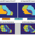
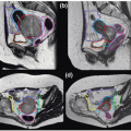
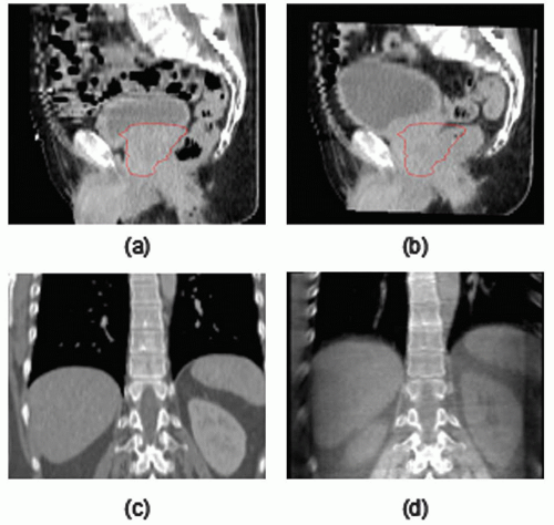 Figure 3.2. Examples of interfraction organ motion for (a and b) prostate and (c and d) liver cancer patients. In both cases, the repeat scan (b and d; computed tomography [CT] for prostate, cone beam CT [CBCT] for liver) has been registered to the bony anatomy of the reference scan (a and c). |
Related posts:
Stay updated, free articles. Join our Telegram channel

Full access? Get Clinical Tree


