Use of Implanted Fiducial Markers in Image-guided Radiation Therapy
Daniel Low
James Balter
The image-guided radiation therapy (IGRT) process involves the detection or measurement of the tumor and normal organs prior to and/or during radiation therapy. In many cases, this can be accomplished by projection x-ray imaging or onboard computed tomography (CT). X-ray imaging (e.g., fluoroscopy) can provide some organ contrast, but this is typically limited to bones and air cavities, so many soft tissue tumors cannot be visualized using projection x-rays. For example, the prostate can be localized using the pelvic bones, but the localization accuracy is within 1 to 2 cm, which is relatively poor compared with the available conformality offered by modern radiation dose optimization and delivery systems.
Onboard CT systems are capable of providing greater soft tissue contrast than projection x-rays, so they are being used extensively in IGRT. When implemented as part of an IGRT program, onboard CT can image bony anatomy, whole organs, air cavities, and in many cases, the gross tumor. Onboard CT does not provide as high-quality imaging as conventional helical CT scanners due to the increased scattered radiation and the slower scan times, which allow for a greater chance for internal organ motion during image acquisition and, consequently, a greater frequency of image artifacts.
Onboard CT systems are also limited by the fact that they acquire the images before or after the treatment and not during the treatment. Tracking of the tumor position during the treatment is not possible with onboard CT, and therefore, treatment of tumors that move due to respiration or that move due to other physiologic processes must include other technologies to allow for monitoring the tumor position during treatment.
The fundamental trade-off of onboard CT is that it provides high resolution in the spatial domain but poor resolution in the temporal domain. Implanted fiducial markers, however, are capable of providing good temporal resolution, but they measure one point at a time, so they have relatively poor spatial resolution (although the localization accuracy of the fiducial markers can be excellent).
NEEDS FOR MARKERS IN IGRT
Implanted fiducial markers are useful for situations where it is sufficient to monitor the position of one or a few locations within the tumor or tumor bed. This is typically true of solid tumors that are encapsulated within an organ or organ system. Examples include the prostate, liver, and breast, either within the tumor or in or near a tumor resection cavity. In these cases, the marker can act as a surrogate for the tumor or tumor bed position.
USE OF FIDUCIAL MARKERS WITH IMAGING SYSTEMS
During the treatment planning process, the markers’ positions are identified within the patient. This can be accomplished by contouring the markers or selecting an “interest point” at the marker position. As the plan is prepared for treatment, the projected locations of radiographic markers for treatment portals and/or orthogonal localization radiographs are established with respect to the projected axes through isocenter. These reference locations are compared with either pretreatment intrafractional kilovoltage (kV) and/or megavoltage (MV) images to initially position the target and/or monitor position changes as treatment progresses.
With the introduction of intensity-modulated radiation therapy (IMRT), the treatment beam orientations may not be conducive for visualization of anatomic landmarks and/or intuitive adjustments of the patient’s position from two-dimensional alignment from images, so imaging fields (typically orthogonal projections) are often added to the treatment plan for purposes of localization. These fields may have different geometries from the treatment fields. The relative position of the markers to the system used to position and align the patient is determined for these imaging fields.
Alignment may be as straightforward as identifying the location of the maker relative to the radiation portal coordinate system. When the patient is set up, an image is acquired in the localization portal geometry and the relative position of the image to the marker is compared against the treatment plan. The patient is repositioned if the imaged fiducial location disagrees with the treatment plan by greater than a predetermined amount.
One challenge of this technique is that a single image does not provide sufficient information to localize the tumor in all three spatial dimensions. Therefore, a second field
orientation is typically used to provide the additional localization information. The second field can be positioned orthogonally to the first, but orthogonality is not required.
orientation is typically used to provide the additional localization information. The second field can be positioned orthogonally to the first, but orthogonality is not required.
Types of Imaging for Fiducial Markers: Radiographic
The image-based method for fiducial marker localization requires acquisition of two or more radiographic images. The most common process for accomplishing this is through the acquisition of MV portal films or images.1, 2, 3, 4, 5, 6, 7 The portal films or images are typically acquired to localize the patient position either before or during the radiation treatment and to use the treatment beam and a portal imager. Typically, the radiation beam is operated at a relatively low dose (1 to 3 cGy) that is sufficient to expose the film or imager. At least two images are acquired with sufficiently large angular separation to allow the measurement of all three spatial coordinates of the marker. Typically, commercial software is used that provides the user with tools to identify the markers on the image, which the software uses to establish the location of the markers in the treatment room coordinate system. This position is compared against the planned position, and the difference is presented to the user so he or she can determine whether the patient needs to be repositioned. If the patient is repositioned, the user generally has the option of reacquiring the images after repositioning to verify that the shift was conducted correctly. Because of the penetration of MV photons to metals, the relatively high scatter-to-primary ratio, and the lack of scatter rejection hardware in portal imagers and MV film cassettes, marker design is critical to visualization and detection with MV imaging. For example, surgical clips often provide insufficient image contrast to allow them to be localized in the image.
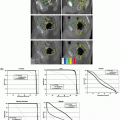
Images can also be acquired using onboard kV systems. Modern linear accelerators are often provided with onboard coregistered kV imaging systems. These systems typically operate at 120 to 140 kVp. The systems consist of x-ray tubes and solid-state imaging panels placed on opposite sides of the linear accelerator isocenter.8 The systems are used to image the patient for positioning purposes, which includes imaging of fiducial markers. The spatial accuracy of coordinate mapping from these images to isocenter is excellent. Additional advantages of using these systems for fiducial localization are that the image orientation can be selected for optimal marker visualization and separation of the two image sets required for three-dimensional (3D) marker localization can be performed. Disadvantages of the onboard fluoroscopic systems include the inability to acquire both images simultaneously, making real-time positioning (e.g., for respiratory motion management) challenging. However, localization of implanted markers with hybrid use of onboard kV and treatment MV beams (Fig. 4.1) is possible during either fixed gantry or arc therapy.9,10 The maximal frames per second (fps) obtainable from the kV and MV detectors in Varian’s Trilogy (Varian Medical Systems, Palo Alto, Calif), for example, are 15 Hz and 9 Hz, respectively. Figures 4.2 and 4.3 demonstrate the technique using a moving pelvic phantom. As can be seen in Figure 4.3, the tracked motion agrees with the known sinusoidal movement of the fiducial embedded in the pelvic phantom to within 1 mm. Similar accuracy was also found in the tracking of fiducial tracking in the arc delivery mode.10
One of the oldest techniques for using fiducial markers for localization involves the use of kV imaging systems that are built into the treatment room rather than attached to the linear accelerator. Two kV x-ray sources are permanently installed (e.g., in the floor) at angles that are typically nearly orthogonal to each other. They aim at the linear accelerator isocenter, and flat panel imagers are positioned on the opposite side (e.g., in the ceiling). The permanent position of the systems allows them to be used independently of the linear accelerator gantry orientation (unless the accelerator head interferes with the imaging projections), and radiograph pairs can be acquired simultaneously, enabling real-time 3D measurements of fiducial marker positions. These systems have the advantage that they use kV energies, so they can image surgical clips and relatively small implanted markers. However, the orientations of these imagers are fixed and are often not optimal for anatomic imaging. Given that they are positioned independent of the linear accelerator, they can be used
during irradiation. This allows some of the room-mounted systems to be used for gating and tracking.
during irradiation. This allows some of the room-mounted systems to be used for gating and tracking.
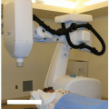
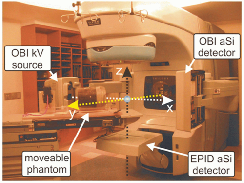 Figure 4.1. Varian Trilogy with kilovoltage (kV) and megavoltage (MV) imagers in extended positions. System’s frame of reference is denoted by dashed arrows. (From Wiersma RD, Mao W, Xing L. Combined kV and MV imaging for real-time tracking of implanted fiducial markers. Med Phys. 2008;35:1191-1198, with permission.) |
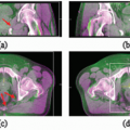
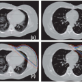
 Figure 4.2. Displayed snapshots of a fiducial in a pelvic phantom for the (a) kilovoltage (kV) and (c) megavoltage (MV) detectors before and after applying the fiducial detection algorithm on the selected regions of interest (ROIs) of the (b) kV and (d) MV video streams. (From Wiersma RD, Mao W, Xing L. Combined kV and MV imaging for real-time tracking of implanted fiducial markers. Med Phys. 2008;35:1191-1198, with permission.) |
Types of Imaging for Fiducial Markers: Electromagnetic
Radiographic markers have the disadvantage that they require that ionizing radiation be used in the process of measuring their positions. Most of them do not have real-time position measurement capabilities.
 Figure 4.3. Plot of the real-time fiducial x, y, and z components as a function of time obtained using simultaneous kilovoltage (kV)/megavoltage (MV) imaging. All motion is with respect to system isocenter. The theoretically sinusoidal function inputted in the motion platform (denoted by the solid curves) agrees well with the measured data points (root mean square [RMS] values of 0.86, 0.55, and 0.70 mm for the x-, y-, and z-axis motion, respectively). (From Wiersma RD, Mao W, Xing L. Combined kV and MV imaging for real-time tracking of implanted fiducial markers. Med Phys. 2008;35:1191-1198, with permission.) |
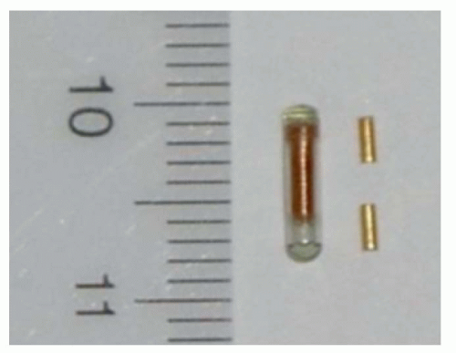 Figure 4.4. An electromagnetic (EM) beacon transponder (1.85 mm × 8 mm) together with two implantable gold fiducials used for image-guided radiation therapy (IGRT). |
Calypso Medical (Seattle, WA) has recently developed a system that uses radiofrequency (RF) energy to localize the marker in real time.11, 12, 13 The markers are small (7 × 1 mm cylinders) RF beacons tuned to one of three frequencies (Fig. 4.4). They are composed of a ferrite core, a small electrical circuit to absorb and reirradiate RF energy, and a glass enclosure. The Calypso system consists of a flat phased-array antenna mounted in an enclosure that is placed above the patient. The position of the antenna relative to the treatment room is monitored by three infrared cameras mounted in the accelerator vault ceiling. The antenna emits RF energy in short bursts. When the RF is turned off, the beacons re-emit the energy, some of which is absorbed by the antenna. The distribution of RF energy received across the complex of antenna components is used to localize the transponder positions. The positioning accuracy of this system is a function of the distance between the transponder and antenna but is better than 2 mm in the nominal operating range (80 to 270 mm from the array).
The Calypso system is operated as a localization device for patient setup, similar to the radiographic techniques. Although the system can, in principle, be used to localize most tumor sites, to date, it has been used primarily in the localization of the prostate. Before the CT simulation, three transponders (beacons) are implanted into the prostate gland. During treatment planning, the beacon positions are identified, and their position relative to isocenter is transferred to the Calypso workstation. Before treatment, the patient is placed on the treatment couch and aligned using external marks and immobilization devices. The antenna is placed over the patient and aligned with the accelerator. This alignment is required to assure that the beacons are within the sensitive range of the antenna and that the antenna position can be accurately tracked using the room-mounted cameras. The system locates the beacons and determines the relative shift of the registration point within the patient to the linear accelerator isocenter. The operator is provided with a real-time readout that he or she uses to aid in the positioning of the registration point to the accelerator isocenter. Once alignment is complete, the operator leaves the linear accelerator vault and begins treatment. The system continuously monitors (at a frequency of approximately 10 Hz) the beacon positions and provides a readout of the distance between the reference point and isocenter. The operator can elect to pause treatment and reposition the patient if the localization point moves significantly from the isocenter.
PARADIGM FOR LOCALIZATION
The basic purpose of implanted fiducial markers is to provide the radiation therapist with a quantitative and efficient
method for localizing the tumor relative to the linear accelerator coordinates. Ideally, positioning the fiducial in the position determined during the treatment planning process will position the tumor within the planned high-dose region and the normal organs within their relatively low-dose regions. However, the actual clinical situation is not as straightforward as it may seem. This section describes the treatment planning process and the subsequent alignment process that is used when implanted fiducial markers are used.
method for localizing the tumor relative to the linear accelerator coordinates. Ideally, positioning the fiducial in the position determined during the treatment planning process will position the tumor within the planned high-dose region and the normal organs within their relatively low-dose regions. However, the actual clinical situation is not as straightforward as it may seem. This section describes the treatment planning process and the subsequent alignment process that is used when implanted fiducial markers are used.
IMPLANTATION PROTOCOL
Because fiducial markers are intended as surrogates to the tumor position, they should be positioned in a location that will remain stable relative to the tumor throughout therapy. Ideally, the marker would be placed within the tumor-bearing tissues, as in the case of prostate cancer. However, this is often not possible. For example, the fiducial markers may be surgical clips implanted during partial resection, so the end user does not have the flexibility of selecting an optimal location.
TREATMENT PLANNING AND PATIENT POSITIONING
If the fiducial marker is located within the tumor-bearing tissue, the process of determining an alignment strategy is more straightforward. The treatment planner will identify the marker positions relative to the intended isocenter or other alignment positions. Once the treatment plan is completed, the relative marker positions are transferred to the software that will be used to determine the marker positions at the linear accelerator. This may be as straightforward as manually entering the relative locations of the markers or as sophisticated as a Digital Imaging and Communications in Medicine (DICOM) transfer of the markers as defined structures. In either case, the localization software will acquire the daily marker positions through some method (e.g., digitized radiographic film or portal images) and compare the position to that downloaded from the treatment plan. The relative positions are used to indicate to the therapist the amount of couch motion required to reposition the patient to place the markers in their intended positions. The therapist then moves the patient, typically by moving the support couch, to the position that will minimize the discrepancy between the measured and planned marker positions. In some clinics, the imaging and analysis procedure is repeated to check that the couch motion was correctly implemented.
REPOSITIONING STRATEGIES
Action Levels
There will always be a discrepancy between the measured and planned position of the fiducial markers. These discrepancies appear both in the individual marker measurements as well as in aggregate measurement (e.g., the center of mass of the positions of multiple markers). The clinic should have a strategy to determine an intervention action level. If the marker positions lie within the action level, then the patient is said to be aligned, even though the planned and measured fiducial markers are not in the same location.
Determining the intervention action level is challenging and is based on numerous factors, including the tumor site, relative positions of the markers to the tumor, dose distribution, planning target volume margins, critical structure margins, patient immobilization hardware, and the ability of the patient to remain stationary. If the action level is made too tight, the intervention will be more frequent than necessary and could occasionally (due to measurement error and repositioning uncertainty) cause the tumor to be farther from the planned position after intervention than before.
The use of thresholds prior to repositioning decisions is a very practical approach for treatment efficiency. More importantly, it can be noted that the impact on treatment margins of a small threshold versus continuous repositioning is relatively small.14,15 Essentially, correction thresholds that are tighter than the limits inherent in measurement and correction will provide no impact on margins for an excess amount of work. Until repositioning is sufficiently integrated in measurement systems for treatment units, such workflow issues should be considered when designing a (marker-based) position adjustment system. Similar arguments apply to the frequency of position adjustment for intratreatment motion of the prostate.16
Temporal Issues
On the surface, the use of fiducial markers appears to be an excellent method of accurately and precisely positioning a tumor within the radiation beam. However, the measurements are limited to a few discrete points, so evaluations of nearby organ position and tumor deformation are difficult to conduct.
One of the advantages of fiducial marker systems is their ability to provide rapid temporal information when they are used with a suitable system. For example, in-room x-ray imagers have been used to monitor lung tumor positions, using the positions to generate a linear accelerator gating signal.17 The high temporal resolution of some marker-based systems allows them to be used to monitor real-time tumor motion due to peristalsis, breathing, and bladder/rectal filling. In addition, there is some evidence that they can be used to manage cardiac motion.
There are a few challenging issues that arise when a marker system is going to be used to guide a time-dependent treatment, including temporal resolution and latency. These limitations are addressed not only by maximizing the temporal resolution and reducing latency, but also by developing predictive models.18,19 The need for high temporal resolution has been noted, as time-dependent marker position measurements are used for gating the treatment beam and tracking the tumor during irradiation.
TEMPORAL RESOLUTION.
The rate at which the marker measurements are made significantly affects the ability to monitor the tumor position. In the temporal domain, the motion frequency needs to be lower than the measurement frequency according to the Nyquist-Shannon sampling theorem. The sampling theorem states that if a function contains no frequencies higher than F Hz, it can be completely determined by providing its coordinates at a series of points spaced 1/2F seconds apart. This theorem fundamentally connects the sampling frequency with the frequency characteristics of the quantity being described (in this case, the measurement of marker motion).
In the case of the prostate, motion is caused by three factors: bladder filling, rectal filling, and patient motion. Bladder filling is typically slow, so determining the motion due to this
effect would require relatively broad temporal measurement spacing. The motion due to rectal filling is often much quicker than with the bladder, so the frequencies of motion are higher. Bowel gas has the greatest frequency and is often characterized by rapid, discrete motions of the prostate. Motion due to bowel gas flow is on the order of seconds, so in order to accurately characterize the motion, the marker measurement rate needs to also be on the order of seconds.
effect would require relatively broad temporal measurement spacing. The motion due to rectal filling is often much quicker than with the bladder, so the frequencies of motion are higher. Bowel gas has the greatest frequency and is often characterized by rapid, discrete motions of the prostate. Motion due to bowel gas flow is on the order of seconds, so in order to accurately characterize the motion, the marker measurement rate needs to also be on the order of seconds.
The measurement of breathing motion involves an understanding of the frequency characteristics of the breathing cycle. The breathing cycle is quasi-periodic, with periods of approximately 5 seconds. If the breathing cycle acted as a pure sine wave, the Nyquist-Shannon sampling theorem states that it would require a measurement every 2.5 seconds. The breathing cycle is more complex, with an asymmetric inhalation and exhalation, and often contains complex features caused by pauses in the inhalation or exhalation process. Therefore, a more conservative measurement frequency is 200 milliseconds. Ignoring breathing motion characteristics with timescales shorter than this should not significantly affect the overall delivered dose distribution.
LATENCY.
The process of using measured marker positions for monitoring a moving tumor is, in essence, the process of real-time measurement. The ultimate use of these measurements may be to gate the linear accelerator, which involves a real-time response to the real-time measurement, vis-à-vis the turning on and off of the linear accelerator in response to the measured tumor position as compared with a predetermined gating window.
Related posts:
Stay updated, free articles. Join our Telegram channel

Full access? Get Clinical Tree


