Breast Imaging: Mammography
Mammography is a radiographic examination that is optimized for detecting breast cancer. Breast cancer screening with mammography can catch cancers at an earlier, more treatable stage. Technological advances over the last several decades have greatly improved the diagnostic sensitivity of mammography. Early x-ray mammography was performed with direct exposure film, required high radiation doses, and produced images of low contrast and poor diagnostic quality. Mammography using the xeroradiographic process was very popular in the 1970s to early 1980s, and featured high spatial resolution and edge-enhanced images; however, poor sensitivity for mass lesions and higher radiation dose compared to screen-film mammography led to its demise in the late 1980s. Screen-film mammography was widely used until full-field digital mammography technology matured in terms of reliability and image quality as verified by the Digital Mammography Imaging Screening Trial (DMIST; Pisano et al., 2005). More recently, digital breast tomosynthesis (DBT) systems using limited angle acquisition introduced in 2011 have rapidly augmented digital mammography with pseudo-3D images that reduce tissue overlap, with improved sensitivity and specificity. Dedicated breast CT is a true three-dimensional modality that promises to also have a role in breast screening and diagnosis (Fig. 8-1). The move from 2D to pseudo 3D to true 3D breast imaging is not without challenges, as the number of images increases and places a greater demand on image interpretation time for the radiologist. One way to meet these challenges is through the application of artificial intelligence (AI) and deep learning algorithms to augment the radiologist in the interpretation of these larger image data sets, but significant work remains to determine how this might come about.
The American College of Radiology (ACR) mammography accreditation program changed the practice of mammography in the mid-1980s, with recommendations for minimum standards of practice and quality control (QC) that led to improvements in image quality. The federal Mammography Quality Standards Act (MQSA) was enacted in 1992; the law and associated federal regulations (Title 21 of the Code of Federal Regulations, Part 900) issued by the US Food and Drug Administration (FDA), made many of the quality assurance (QA) procedures of the accreditation program mandatory, making mammography the only federally regulated imaging modality in the United States. For digital mammography systems, the performance evaluation requires following and adhering to the manufacturer’s QC procedures. An optional alternative has been FDA-approved as a harmonized, manufacturer-independent QC program for digital mammography and DBT by the ACR, as published in the 2018 ACR Digital Mammography Quality Control Manual.
Breast cancer screening programs depend on x-ray mammography because it is a low-cost, low-radiation dose procedure that has the sensitivity to detect earlystage breast cancer. Mammographic features characteristic of breast cancer include masses, particularly ones with irregular or “spiculated” margins; clusters of microcalcifications; and architectural distortions of breast structures. In screening mammography as practiced in the United States, two x-ray images of each breast, in the
mediolateral oblique and craniocaudal views, are acquired. Whereas screening mammography attempts to detect breast cancer in the asymptomatic population, diagnostic mammography procedures are performed to assess and delineate lesions identified by screening mammography. The diagnostic mammographic examination may include additional x-ray projections, magnification views, spot compression views, tomosynthesis, ultrasound, magnetic resonance imaging (MRI), mammoscintigraphy, or breast CT.
mediolateral oblique and craniocaudal views, are acquired. Whereas screening mammography attempts to detect breast cancer in the asymptomatic population, diagnostic mammography procedures are performed to assess and delineate lesions identified by screening mammography. The diagnostic mammographic examination may include additional x-ray projections, magnification views, spot compression views, tomosynthesis, ultrasound, magnetic resonance imaging (MRI), mammoscintigraphy, or breast CT.
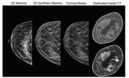 ▪ FIGURE 8-1 Improvements in mammography and breast x-ray imaging. Images of a cranial-caudal view and coronal tomographic slice of the breast are shown. On the left is a 2-dimensional (2D) full-field digital mammogram (acquired after tomosynthesis study). On the middle left is a 2D synthetic mammogram created from the digital breast tomosynthesis exam on the middle right; shown is a 1-mm focal plane image of ˜60 images depicting several lesions made more conspicuous. On the right are reconstructed coronal slices of the breast (of about 500) positioned at the site of the lesions from pre- and postcontrast injection acquisitions using a dedicated breast CT scanner. The contrast enhanced image (bottom) shows significant uptake in glandular tissues as a biomarker for malignancy. This illustrates the power of full 3D tomography and the benefits of no tissue overlap provided by dedicated breast CT. |
Ultrasound (Chapter 14) is often used to differentiate cysts (typically benign) from solid masses (often cancerous) using anatomic appearance or elastography evaluation, or for biopsy needle guidance. Automated breast ultrasound systems are used as supplemental screening options for women with dense breast tissue. MRI (Chapters 12 and 13) has excellent tissue contrast sensitivity and can differentiate benign from malignant tumors with contrast enhancement by evaluating signal intensity-time curves. MRI is used for diagnosis, staging, and biopsy guidance, and for screening of high-risk women. Mammoscintigraphy with Tc-99m sestamibi as the radiotracer is used to evaluate suspected breast cancer in patients for whom mammography is non-diagnostic. It is also used to assist in identifying multicentric and multifocal carcinomas in patients already diagnosed with breast cancer.
The specific requirements of breast cancer imaging, including the differentiation of normal and cancer tissues and visualization of microcalcifications require the use of x-ray equipment specifically designed for breast imaging. As shown in Figure 8-2A, the difference in attenuation between normal and cancer tissue is extremely small. Subject contrast, shown in Figure 8-2B, is highest at low x-ray energies (10 to 15 keV)
and decreases with higher energies. Low x-ray energies provide the best differential attenuation between breast tissues; however, the high absorption at these low energies results in higher radiation doses. Detection of microcalcifications in the breast is also important because they are often early markers of breast cancer. The need to visualize microcalcifications requires x-ray tubes with small focal spots and very high-resolution detectors. Enhancing contrast sensitivity, reducing dose, and providing the spatial resolution necessary to depict microcalcifications impose challenging requirements on mammographic equipment and detectors. Therefore, dedicated x-ray equipment design, specialized x-ray tubes, breast compression devices, antiscatter grids, digital x-ray detectors, and automatic exposure control (AEC) subsystems are essential for mammography (Fig. 8-3).
and decreases with higher energies. Low x-ray energies provide the best differential attenuation between breast tissues; however, the high absorption at these low energies results in higher radiation doses. Detection of microcalcifications in the breast is also important because they are often early markers of breast cancer. The need to visualize microcalcifications requires x-ray tubes with small focal spots and very high-resolution detectors. Enhancing contrast sensitivity, reducing dose, and providing the spatial resolution necessary to depict microcalcifications impose challenging requirements on mammographic equipment and detectors. Therefore, dedicated x-ray equipment design, specialized x-ray tubes, breast compression devices, antiscatter grids, digital x-ray detectors, and automatic exposure control (AEC) subsystems are essential for mammography (Fig. 8-3).
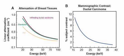 ▪ FIGURE 8-2 A. Attenuation of breast tissues as a function of energy, showing fat, glandular, and ductal carcinoma linear attenuation coefficients. Comparison of the three tissues shows a very small difference between the glandular and the cancerous tissues. B. Calculated percentage contrast of the ductal carcinoma relative to the glandular tissue declines rapidly with energy; contrast is optimized using a low energy, nearly monochromatic x-ray spectrum. (Adapted from Yaffe MJ. Digital mammography. In: Haus AG, Yaffe MJ, eds. Syllabus: A Categorical Course in Physics: Technical Aspects of Breast Imaging. Oak Brook, IL: RSNA; 1994:275-286. Copyright © Radiological Society of North America.) |
Strict QC procedures to verify optimal system performance and assure communication teamwork by the technologist, radiologist, and medical physicist are necessary to ensure high-quality breast imaging at a facility. The technical and physical considerations of mammographic x-ray imaging are discussed in this chapter. Many
of the basic concepts regarding image quality, x-ray production, and radiography are presented in Chapters 4, 6, and 7, respectively. The applications of these concepts to mammography, together with many new topics specific to mammography, are presented here.
of the basic concepts regarding image quality, x-ray production, and radiography are presented in Chapters 4, 6, and 7, respectively. The applications of these concepts to mammography, together with many new topics specific to mammography, are presented here.
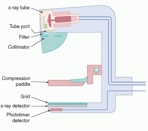 ▪ FIGURE 8-3 A dedicated mammography system has many unique attributes, including K-edge filtration, collimation, and compression. Automatic Exposure Control (AEC) has an external or internal sensor for digital detectors and can be positioned by the user. Major components of a typical system, excluding the generator and user console, are shown. |
8.1 X-RAY TUBE COMPONENTS, STRUCTURES, AND OPERATION
This section compares and contrasts the differences between mammography and general radiography x-ray tubes.
8.1.1 Cathode
The mammography x-ray tube is configured with dual filaments in the focusing cup to produce 0.3- and 0.1-mm focal spot sizes, with the latter used for magnification studies to reduce geometric blurring. An important distinction between mammography and conventional x-ray tube operation is the low operating tube potential, below 40 kV. The tube current is also limited to 100-200 mA for the large (0.3 mm) focal spot and 25-50 mA for the small (0.1 mm) focal spot depending on the target material.
8.1.2 Anode
Molybdenum (Mo) (Z = 42) is a common anode target material used in mammography x-ray tubes by some manufacturers, and one manufacturer also has a rhodium (Rh) (Z = 45) target material. K-shell characteristic x-rays are generated with energies of 17.5 and 19.6 keV for Mo and 20.2 and 22.7 keV for Rh, within the optimal energy range for thin to thick compressed breast tissues. Tungsten (W) is also a common anode material because of its increased x-ray production efficiency due to its high atomic number (Z = 74) and high heat loading capability. However, because of unwanted low-energy (8-10 keV) L-shell characteristic x-ray emission, thicker x-ray tube filtration is required, which reduces some of the output advantages of tungsten. Digital detectors enable postacquisition image processing, which can enhance contrast. Thus, the characteristic radiation from Mo or Rh is not as important in digital mammography as it was for contrast-limited screen-film mammography.
Mammography x-ray tubes have rotating anodes, with anode angles ranging from 0° to 16°, depending on the manufacturer. The tubes are typically positioned at a source-to-image distance (SID) of 65-70 cm. In order to achieve adequate field coverage on the anterior (nipple) side of the field, the x-ray tube must be physically tilted so that the effective anode angle (the actual anode angle plus the physical tube tilt) is at least 22° for coverage of a common 24 × 30-cm field area at the SID. Details of the tube field coverage are illustrated in Figure 8-4.
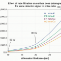
The intensity of the x-rays emitted from the focal spot varies across the field of view (FOV), with the highest x-ray fluence on the cathode side of the field and the lowest x-ray fluence on the anode side, a consequence of the heel effect (Chapter 6). Positioning the x-ray tube such that the cathode-anode axis runs posterior to anterior achieves better uniformity of the x-rays transmitted through the compressed breast (Fig. 8-5), as the compressed breast is thicker near the chest wall (posterior) and thinner towards the nipple (anterior). Orientation of the tube in this way also decreases the equipment bulk near the patient’s face. For a “uniform” exposure on the detector,
digital values on the anterior (anode) side of the field will be consistently less. For fixed, non-removable digital flat-panel detectors, the reduced fluence on the anode side of the field can be corrected with “flat-fielding” procedures to adjust the digital number uniformity across the FOV (see Section 8.5). However, the quantum noise (and thus the standard deviation of the digital numbers) will be higher in this area due to reduced x-ray fluence.
digital values on the anterior (anode) side of the field will be consistently less. For fixed, non-removable digital flat-panel detectors, the reduced fluence on the anode side of the field can be corrected with “flat-fielding” procedures to adjust the digital number uniformity across the FOV (see Section 8.5). However, the quantum noise (and thus the standard deviation of the digital numbers) will be higher in this area due to reduced x-ray fluence.
 ▪ FIGURE 8-4 Design of a dedicated mammography system includes unique geometry and x-ray tube design. A collimated “half-field” geometry projects the x-ray beam central axis perpendicular to the plane of the image receptor at the chest wall, and centered horizontally. Full-area x-ray beam coverage at 60- to 70-cm SID and 24 cm depth (posterior to anterior) requires a tube tilt of about 20° to 24° to avoid cutoff on the anode side of the field. A. An anode angle of 0° requires a tube tilt of 24°. B. An anode angle of 16° requires a tube tilt of about 6°. |
8.1.3 Focal Spot
Focal spot dimensions are small compared to general radiography tubes. Sizes of 0.3 to 0.4 mm for contact mammography and 0.10 to 0.15 mm for magnification exams are necessary to limit geometric blurring onto the detector so that fine detail microcalcifications can be resolved in the images. By convention, the nominal focal spot size is measured at a reference axis, which bisects the x-ray field along the chest wall—anterior direction (Fig. 8-6A), since all mammography systems utilize a “half-field” x-ray beam geometry where the central axis of the x-ray beam (the “central ray”) is positioned at the chest wall edge of the detector and perpendicular to the image detector surface. Nominal focal spot size and tolerance limits for the width and length are listed in Table 8-1. As a consequence of the effective focal spot size variation in the field (the line focus principle, see Chapter 6, Fig. 6-16), sharper image detail is rendered on the anode (anterior) side of the field toward the nipple and is more evident with magnification examinations, as described in Section 8.3.
System resolution is a combination of geometric (focal spot) and detector resolution, measured with a high-resolution bar pattern with frequencies from 4 to 20-line pairs/mm. For contact breast imaging, the bar pattern is placed 4.5 cm above the breast support platform near the chest wall edge, corresponding to the entrance surface of the average breast. For magnification imaging, the pattern is placed 4.5 cm
above the magnification platform. Orientation of the bar pattern parallel and perpendicular to the cathode-anode direction of the x-ray tube yields measurements of overall effective resolution including the focal spot length and width dimensions, the acquisition geometry, and the detector sampling characteristics. Orientation at a 45° angle yields a resolution measurement up to a factor of 1.4 times higher, resulting
from the increased physical distance between bars of the bar pattern relative to the detector element sampling array and when the focal spot does not limit resolution. Without correction for bar pattern spacing at an angle, the reported resolution can exceed the theoretical maximum resolution of a detector defined by the Nyquist sampling criterion (see Chapter 4). A resolution bar pattern is shown in Figure 8-6B for contact and magnification images using 0.3- and 0.1-mm focal spots, respectively. The resolving capability of the imaging system is limited by the component that
causes the most blurring. In magnification mammography, this is generally the focal spot, whereas in contact mammography, it may be the detector element size. In clinical breast imaging, patient motion can be the limiting factor.
 ▪ FIGURE 8-5 The x-ray tube is oriented with the cathode over the chest wall side and the anode over the anterior side of the breast. X-ray fluence is reduced on the anode side of the field, a result of self-filtration of x-rays by the anode known as the heel effect. The thickest part of the breast (at the chest wall) is positioned below the cathode, which helps equalize the transmitted x-ray fluence reaching the image receptor. The bottom illustration shows the reduction in fluence to zero, from the projection parallel to the anode surface. Note that with magnification (moving the breast towards the focal spot), the heel effect becomes more prominent over the imaged breast. |
 ▪ FIGURE 8-6 Focal spot size and image resolution. A. The actual focal spot size is determined by the electron distribution area incident on the anode (width × length). The nominal focal spot size is specified on a reference axis bisecting the field from the cathode to the anode, with 0.3- and 0.1-mm sizes typical. The projected focal spot length increases towards the chest wall and decreases towards the anterior side of the breast according the line focus principle. B. A resolution bar pattern measures overall system resolution, including detector sampling and geometric magnification. For contact mammography using a 0.3-mm focal spot with the pattern 6 cm above the detector plane (1.09× magnification), a resolution of 9 lp/mm is resolved. For magnification using a 0.1-mm focal spot with the pattern 35 cm above the detector plane (2.0× magnification), a resolution of 13 lp/mm is resolved. These measurements are for a source-image distance (SID) of 70 cm, 0.07 mm detector element size, and bar pattern at 45° to the detector array. |
TABLE 8-1 NOMINAL FOCAL SPOT SIZE AND MEASURED TOLERANCE LIMITS OF MAMMOGRAPHY X-RAY TUBES SPECIFIED BY IEC STANDARDS | ||||||||||||||||||||||||
|---|---|---|---|---|---|---|---|---|---|---|---|---|---|---|---|---|---|---|---|---|---|---|---|---|
| ||||||||||||||||||||||||
8.1.4 Tube Port, Tube Filtration, and Beam Quality
The tube port and added tube filters play an important role in shaping the mammography x-ray photon spectrum. The x-ray tube port window is made of beryllium (Be). The low atomic number (Z = 4) of Be and the thin window (0.5 to 1 mm) allow the transmission of all but the lowest energy (5 keV and less) bremsstrahlung x-rays. In addition, Mo and Rh targets produce beneficial K-characteristic x-ray peaks at 17.5 and 19.6 keV (Mo) and 20.2 and 22.7 keV (Rh) (see Chapter 6, Table 6-2), whereas W targets produce a large fraction of undesirable L-characteristic x-rays at 8 to 10 keV that will deliver dose with little or no contribution to image formation. Figure 8-7 illustrates the contributions of the bremsstrahlung and characteristic radiation to the unfiltered composite x-ray spectrum generated by an x-ray tube operated at 30 kV with a Mo target and Be tube port window.
Added x-ray tube filtration helps to optimize the energy distribution of the mammography output spectrum by selectively removing the lowest and highest energy x-rays from the x-ray beam, while transmitting a band of x-ray energies that produces acceptable image quality at reasonable dose. This is accomplished by using
thin, uniform sheets of pure metal comprised of elements with a K-absorption edge energy (Chapter 3) between 20 and 26 keV, including Mo (20.0 keV), Rh (23.2 keV), and Ag (25.5 keV). At the lowest x-ray energies in the spectrum, the beam attenuation by these filters is very high. The attenuation decreases as the x-ray energy increases up to the K-edge of the element constituting the filter. For x-ray energy just above the K-edge, photoelectric absorption by interaction with the K-shell electron creates a step increase of ˜6× in attenuation, and then decreases with higher x-ray energies (Fig. 8-8A). Selective transmission of x-rays in a narrow band from about 15 keV up to the K-absorption edge energy of the filter is achieved with the added filter. In Figure 8-8B, an unfiltered Mo target spectrum and a superimposed attenuation curve for a Mo filter are shown. Note: the characteristic x-ray energies produced by the Mo target occur at the lowest attenuation by the filter in this energy range.
thin, uniform sheets of pure metal comprised of elements with a K-absorption edge energy (Chapter 3) between 20 and 26 keV, including Mo (20.0 keV), Rh (23.2 keV), and Ag (25.5 keV). At the lowest x-ray energies in the spectrum, the beam attenuation by these filters is very high. The attenuation decreases as the x-ray energy increases up to the K-edge of the element constituting the filter. For x-ray energy just above the K-edge, photoelectric absorption by interaction with the K-shell electron creates a step increase of ˜6× in attenuation, and then decreases with higher x-ray energies (Fig. 8-8A). Selective transmission of x-rays in a narrow band from about 15 keV up to the K-absorption edge energy of the filter is achieved with the added filter. In Figure 8-8B, an unfiltered Mo target spectrum and a superimposed attenuation curve for a Mo filter are shown. Note: the characteristic x-ray energies produced by the Mo target occur at the lowest attenuation by the filter in this energy range.
 ▪ FIGURE 8-7 The x-ray spectrum of a mammography x-ray tube is composed of bremsstrahlung (with a continuous photon energy fluence) and characteristic (discrete energy) radiation (see Chapter 6 for more details). A Mo anode tube operated at 30 kV creates the continuous spectrum (upper right) as well as characteristic radiation with photon energies of 17.5 and 19.6 keV (middle right). On the lower right, the “unfiltered” composite spectrum transmitted through 1 mm of Be (tube port material) has a large fraction of low-energy x-rays that deposits high dose without contributing to the image, and a substantial fraction of high-energy x-rays that reduces subject contrast of the breast tissues. The ideal spectral energy range (shaded in green) is from ˜15 to ˜25 keV, depending on breast tissue composition and thickness. |
 ▪ FIGURE 8-8 A. The linear attenuation coefficients of Al, Mo, Rh, and Ag are plotted as a function of energy. A low-attenuation “transmission window” exists below the K-absorption edge energy for the higher Z elements. B. An unfiltered Mo target spectrum generated at 30 kV shows a large fraction of low- and high-energy photons. Superimposed on the same energy scale is a dashed line illustrating Mo filter attenuation as a function of energy (attenuation values from Fig. A). |
The spectral output of a Mo target and 0.030-mm-thick Mo filter is shown in Figure 8-9A, illustrating the selective transmission of Mo characteristic radiation and significant attenuation of the lowest and highest x-rays in the transmitted spectrum. The Mo target/Mo filter is used for thin and adipose-replaced breasts, with lower (25-30) kV settings. For thicker and more glandular compressed breasts, a 0.025-mm-thick Rh filter produces a higher effective energy beam by transmitting higher energy bremsstrahlung x-rays above 20 keV as shown in Figure 8-9B, with higher (28-32) kV settings.
For systems using the Rh target of a dual Mo and Rh anode, the benefit achieved is the production of Rh characteristic x-ray energies at 20.2 and 22.7 keV. With a 0.025 mm Rh filter, higher effective energy for a set kV can be achieved (Fig. 8-10A) compared to a Mo target. An incompatible combination is a Mo filter with a Rh target, because characteristic x-rays from Rh are significantly attenuated by the Mo filter (Fig. 8-10B). The use of a silver (Ag) filter of 0.025 mm thickness can produce another step up in effective energy when used with a Rh target spectrum by transmitting bremsstrahlung x-rays up to the K-edge energy of Ag (25.5 keV).
W targets are used for many digital mammography systems due to higher bremsstrahlung production efficiency and higher anode heat loading capacity compared to Mo and Rh targets, but the very large fraction of L characteristic x-rays in the 8- to 12-keV range (Fig. 8-11A) must be removed to negligible levels, requiring a thicker filter. Selectable K-edge filters of Rh or Ag are used to shape the output x-ray energies within a narrow continuous spectral range, with minimum filter thickness of
0.05 mm, as shown in Figure 8-11B. Consequently, the output fluence rate of a W target is lower than Mo or Rh targets mainly because of the doubled filter thickness (0.05 mm compared to 0.025 mm). Higher fluence rate for a W target is achieved by using an Al filter of 0.5-0.7 mm thickness to sufficiently attenuate the L x-rays of lower energy and permit a larger fraction of higher energy x-rays in the transmitted spectrum. In breast tomosynthesis implemented by one vendor, requirements for rapid image capture are satisfied by the W/Al selection, and the loss of tissue subject contrast by the higher energy spectrum is offset by image reconstruction processing with reduced superimposition of tissues in the tomographic images, as well as digital contrast enhancement (see Section 8.5).
0.05 mm, as shown in Figure 8-11B. Consequently, the output fluence rate of a W target is lower than Mo or Rh targets mainly because of the doubled filter thickness (0.05 mm compared to 0.025 mm). Higher fluence rate for a W target is achieved by using an Al filter of 0.5-0.7 mm thickness to sufficiently attenuate the L x-rays of lower energy and permit a larger fraction of higher energy x-rays in the transmitted spectrum. In breast tomosynthesis implemented by one vendor, requirements for rapid image capture are satisfied by the W/Al selection, and the loss of tissue subject contrast by the higher energy spectrum is offset by image reconstruction processing with reduced superimposition of tissues in the tomographic images, as well as digital contrast enhancement (see Section 8.5).
 ▪ FIGURE 8-9 A. A filtered output spectrum is shown for a Mo target and 0.030-mm Mo filter for a 30-kV tube voltage, with prominent characteristic peaks at 17.5 and 19.6 keV. This spectrum is selected for less dense and thinner breast tissues, particularly with lower operating tube voltages (25 to 30 kV). B. A filtered output spectrum is shown for a Mo target and 0.025-mm Rh filter, superimposed on the Mo/Mo spectrum in (A), indicating the transmission of higher energy bremsstrahlung x-rays up to the K absorption edge of Rh at 23.2 keV. The spectrum, including the Mo characteristic x-rays, has a higher effective energy and is preferable for imaging thicker and denser breast tissues. |
 ▪ FIGURE 8-10 A. A filtered output spectrum is shown for a Rh target and 0.025-mm Rh filter for a 30-kV tube voltage, with prominent Rh characteristic x-rays at 20.2 and 22.7 keV. This spectrum provides a higher effective energy than a Mo target—Rh filter x-ray beam at the same kV, due to the presence of higher energy characteristic x-rays. B. A combination of a Rh target and Mo filter is inappropriate, as the Rh characteristic x-rays are strongly attenuated by the Mo filter at the energies of the Rh characteristic x-rays, as shown. |
 ▪ FIGURE 8-11 A. An unfiltered W target spectrum generated at 30 kV shows a large fraction of lower energy L-characteristic x-rays from 8 to 11.5 keV. Superimposed at the same energy scale is a dashed line illustrating the relative attenuation characteristics of a Rh filter. B. Filtered W-target x-ray spectra by Rh (0.05 mm), Ag (0.05 mm), and Al (0.7 mm) are normalized to the same exposure output. The L x-rays are reduced to negligible levels by using the indicated thicknesses. |
8.1.5 Half-Value Layer
The half-value layer (HVL) of a mammography x-ray beam is the thickness of an attenuator (usually Al) required to reduce the incident x-ray beam air kerma by one half. HVL depends on kV, target material (Mo, Rh, W), filter material (Mo, Rh, Ag, Al), and filter thicknesses typically used in mammography, and ranges between 0.3 and 0.7 mm Al (Fig. 8-12). Measurement of HVL is performed with the compression paddle well above the breast platform and collimation in a narrow beam configuration (see Chapter 3) with the radiation dosimeter placed in the beam on the breast platform. At a fixed kV and mAs, repeated measurements of air kerma are made, first with no added filter (other than the compression paddle), then with sequential 0.1 mm sheets of 0.999 purity Al added near the tube port, until the air kerma value drops below one half of the first measurement. The HVL is determined by identifying the nearest added thicknesses corresponding to air kerma values below and above the 50% air kerma value and then using mathematical or graphical interpolation to determine the Al thickness that corresponds to the 50% air kerma value.
An x-ray beam with a Mo target, 0.03-mm Mo filter, and 1.5 mm Lexan compression paddle at 28 kV has an HVL of about 0.35-mm Al, whereas a W target and 0.05-mm Rh filter with the same kV and compression paddle has an HVL of about 0.53-mm Al. HVLs of mammography beams for a set kV and target/filter combination vary from machine to machine because of slight variations in actual filter thicknesses, compression paddles, and kV accuracy.
The minimum HVL in mm Al of an x-ray beam per MQSA regulations must be greater than or equal to kV/100. For example, a mammography system operated at 30 kV must have an HVL ≥ 0.3 mm Al. Under this HVL condition, a large fraction of very low energy x-rays is removed by inherent and added filters in the bremsstrahlung spectrum incident on the breast. Maximum HVL limits have been suggested in earlier accreditation guidelines but are not enforced. An x-ray beam that is “harder” than optimal indicates a problem such as a pitted anode or aged tube and can result in reduced output and poor image quality. Estimates of the radiation dose to the breast glandular tissues require accurate assessment of the HVL (see Section 8.6).
 ▪ FIGURE 8-12 The HVL (including the Lexan compression paddle attenuation) versus kV is plotted for Mo targets with Mo and Rh filters, and for W targets with Rh, Ag, and Al filters. HVL measurements are representative of an average of several evaluations on various mammography systems at UC Davis Health. The solid lines represent a second-order polynomial fit to the data. |
The HVL of breast tissue is highly dependent on tissue composition (glandular, fibrous, or fatty) and the HVL of the incident x-ray beam. Typically, the HVL expressed as breast tissue thickness is from 1 to 3 cm.
8.1.6 Tube Output and Tube Output Rate
While the energy fluence of the x-ray beam best describes output, the air kerma is easily measured and is a practical measure of output. Air kerma is typically normalized to 100 mAs, at a specified distance from the source (focal spot). In this chapter, the x-ray tube output is expressed in units of mGy/100 mAs at 50 cm from the source. The kV, anode target, filter material, filter thickness, and focal spot size must also be specified. X-ray tube output curves for Mo and W targets are shown for several filters and thicknesses as a function of kV in Figure 8-13. Even though W targets are more efficient at producing x-rays, thicker added filters result in lower x-ray tube output rate compared to a Mo target. However, W spectra have higher HVLs and greater beam penetrability (i.e., more of the incident x-ray beam on the breast reaches the detector), and with higher possible maximum tube current, exposure times are comparable to a Mo target/filter for a similar breast thickness.
Calibrated output values of an x-ray tube X mGy (per 100 mAs at 50 cm) for a specific target/filter combination and kV (Fig. 8-13) are necessary for calculating the free-in-air incident air kerma, Z mGy, to the breast for an acquisition requiring Y mAs at a source-to-breast surface distance, D, according to Equation 8-1:

The source-to-breast surface distance, D, is determined from the compressed breast thickness, the source to image (detector) distance (SID), and the breast platform to detector distance. Entrance surface air kerma to the breast is adjusted by the inverse square law relative to the output calibration distance (50 cm/D cm)2.
 ▪ FIGURE 8-13 Tube output (mGy/100 mAs at 50-cm distance from the source with compression paddle in the beam) for two clinical mammography units is measured at 2-kV intervals. A Mo target with 0.03-mm Mo and 0.025-mm Rh filter, and a W target with filter thicknesses of 0.05-mm Rh, 0.05-mm Ag, and 0.70-mm Al are plotted. |
EXAMPLE: Calculate the entrance surface breast air kerma for the following acquisition: W target and Rh filter, technique of 30 kV and 200 mAs, SID of 70 cm, compressed breast thickness of 6 cm, breast platform to detector distance of 2 cm.
Answer: The source to breast surface is 62 cm (SID [70 cm] – breast thickness [6 cm] – space between platform and detector [2 cm]). From Figure 8-13, the tube output for W/Rh at 30 kV is 7.2 mGy/100 mAs at 50 cm. Calculation of incident air kerma considers tube output, the mAs used, and inverse square law correction from 50 cm (calibration point) to 62 cm (breast surface distance), using Equation 8-1:

Calculation of the mean glandular dose (MGD) to the breast is determined from the measured incident breast surface air kerma value and other parameters as discussed in Section 8.6.
Tube output rate is the air kerma rate at a specified distance from the x-ray focal spot and is a function of the tube current achievable for an extended exposure time (typically ˜300 mAs for an exposure time greater than 3 seconds). Legacy systems are required to be capable of producing an air kerma rate of at least 7.0 mGy/s, when operating at 28 kV in the standard (Mo/Mo) mammography mode, at any SID for
which the system is designed to operate. With the introduction of W targets and lower output rates, each manufacturer has set a lower acceptable output rate limit for a designated kV and filter for this test.
which the system is designed to operate. With the introduction of W targets and lower output rates, each manufacturer has set a lower acceptable output rate limit for a designated kV and filter for this test.
8.1.7 X-ray Tube Alignment and Beam Collimation
The x-ray tube and collimation alignment with respect to the light field, active detector area, and compression paddle ensure that the x-ray beam central axis is perpendicular to and intercepts the center of the chest wall edge of the image receptor. This protects the patient from unnecessary radiation dose to the lungs and includes as much breast tissue as possible in the image. Figure 8-14 shows the projected light field and x-ray field for a 24 × 29 cm detector area, and the corresponding detected x-ray image. Congruence is verified for the light and x-ray fields, and by matching the edges of the coins with the x-ray field edges, the x-ray field projects beyond the active detector area in the worst case by about 5 mm, or about 0.7% for a 70 cm SID. Also, the chest wall edge alignment with the compression paddle edge (5 mm) is within the allowable tolerance of 1% of the SID, or 7 mm. Details on the tolerance limits for light field/x-ray field congruence and requirements for x-ray field alignment with the active detector and compression paddle edge are described in the MQSA program requirements (FDA, 2020). See also Section 8.7.
 ▪ FIGURE 8-14 Light field to x-ray field and x-ray field to detector congruence and alignment evaluations. Upper left: The light field is projected onto phosphor plate with coins placed at light field edges. Upper middle: X-ray field generates green luminescence, indicating the coin positions and demonstrating good light-field-x-ray field congruence. Upper right: Acquired image of coins and measurement of coin to field edge distance to determine x-ray field to active detector congruence. Lower: Compressed 40 mm attenuator thickness and coin placed at the edge of the compression paddle to evaluate paddle edge alignment and missed tissue at the chest wall in the acquired x-ray image. |
 ▪ FIGURE 8-15 The large field of view area digital detector size is typically 24 cm × 30 cm, for imaging a large breast. For small breast size, the field of view is reduced to 18 cm × 24 cm with adjustment of the collimator and reduction of the digital image matrix. For cranial-caudal views, the active detector area is centered, as shown in the middle diagram. A shift of the field to the left and right edges of the large area detector provides improved patient positioning of the shoulder and arm for the medial-lateral oblique projections. |
Two detector sizes are commonly used in mammography: 24 cm × 30 cm to accommodate larger breasts and 18 cm × 24 cm for the remainder. For flat-panel digital detectors, adjustable collimator blades direct the x-ray beam to the active detector area. When operating with the small field area, one of three active acquisition areas is used: center for the cranial-caudal (CC) views; left shift and right shift for the medial-lateral oblique (MLO) views. This requires the collimator assembly to restrict the x-ray field to the corresponding active detector areas. Shifts to the left and right edges of the receptor are used for optimizing the oblique projections for subjects with smaller breasts to accommodate positioning of the arm and shoulder (Fig. 8-15).
8.2 MAMMOGRAPHY X-RAY GENERATOR
A dedicated mammography x-ray generator is like a conventional x-ray generator in design and function. Lower voltages supplied to the x-ray tube are used, and space charge compensation is more of a concern. In most cases, AEC is employed for mammography screening and diagnostic examinations, although there are instances when the technologist will use manual controls to set the tube current-exposure time product (mAs). Like most contemporary x-ray imaging systems, high-frequency generators are used for mammography due to low voltage ripple, fast response, easy calibration, long-term stability, and compact size. There are sensors that prohibit x-ray exposures if the setup is incomplete (e.g., insufficient compression, cassette not in the tunnel for computed radiography [CR] detectors, or the digital detector array is not ready to capture an image).
8.2.1 Automatic Exposure Control
The AEC circuit employs one or more radiation sensors, a charge to voltage amplifier, a voltage comparator, and a reference voltage selector to control the exposure (Fig. 8-16A). For cassette-based CR image receptors, the dosimeter sensor is located underneath the cassette, and consists of a single ionization chamber or an array of three or more semiconductor diodes that can be physically positioned by the technologist. For flat panel detectors (FPDs), the AEC signal is generated by the detector, and the sensor area is selected by the user at the generator console as a choice of several (˜5) discrete small square areas spaced equally from the central axis at the chest wall edge to about the middle of the detector. In “auto AEC” mode, the sensor
area is defined by the lowest signal region (highest attenuation) over the active digital detector area. The AEC sensor is wired to a charge to voltage amplifier that produces voltage in proportion to the accumulated x-ray exposure. The voltage comparator circuit has a calibrated reference voltage as one input, and the AEC sensor voltage as the other input. During an exposure, the sensor voltage increases from zero volts to a voltage equal to the reference voltage, which triggers the comparator circuit to terminate the exposure. The reference voltage produces a known incident x-ray fluence to the detector and thus determines the radiation exposure to the breast, as well as the quantum mottle in the digital image.
area is defined by the lowest signal region (highest attenuation) over the active digital detector area. The AEC sensor is wired to a charge to voltage amplifier that produces voltage in proportion to the accumulated x-ray exposure. The voltage comparator circuit has a calibrated reference voltage as one input, and the AEC sensor voltage as the other input. During an exposure, the sensor voltage increases from zero volts to a voltage equal to the reference voltage, which triggers the comparator circuit to terminate the exposure. The reference voltage produces a known incident x-ray fluence to the detector and thus determines the radiation exposure to the breast, as well as the quantum mottle in the digital image.
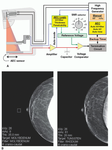 ▪ FIGURE 8-16 A. Automatic exposure control (AEC) circuits use several selectable algorithms to determine the optimal exposure to the breast. The basic AEC operation uses the signal measured by the AEC sensor during the exposure in an operator positioned region that is transmitted to a comparator circuit to match a predetermined level that sends a signal to the generator to terminate the exposure. This is commonly known as “Auto-time.” More sophisticated modes are also available, as explained in the text. B. Left: Image is an implant displaced view of the breast. The square in the open field represents the position of the AEC sensor, which was set in the open field from the previous acquisition, causing an underexposure and significant noise. Right: Patient returns for repeat study on a different unit using AEC “auto” mode that determines the attenuation characteristics of the breast and achieves a proper exposure. Note the technique factors for each acquisition. |
AEC algorithms use several inputs to achieve a consistent detected x-ray fluence, including compressed breast thickness, AEC control selector settings on the generator console, kV, tube anode selection (if available), and tube filter. The operator typically has two or three options for AEC settings:
A fully automatic AEC mode that sets the optimal kV and filtration (and target material on some systems) from a short test exposure of approximately 100 ms to determine the penetrability of the breast.
Automatic kV selection with a short test exposure, with user-selected target and filter values.
Automatic time of exposure using manually set target, filter, and kV values.
For most patient imaging, the fully automatic mode is used.
At the generator control panel, an exposure selector control modifies the AEC reference voltage to the comparator circuit to permit adjustments for unusual imaging circumstances such as imaging breasts with implants, magnification, or for radiologist preference in overall digital image signal to noise ratio (SNR) in the output image. Depending on the manufacturer, several steps (e.g., -3 to 0 [neutral] to +4) are available to increase or decrease exposure by adjusting the AEC input level to the comparator circuit. Each step provides a difference of 10% to 15% positive (greater exposure) or negative (lesser exposure) per step from the baseline neutral (0) setting.
An x-ray exposure under AEC control that exceeds a preset time (e.g., greater than 5 s) is terminated by a backup timer. This can occur if there is a malfunction of the AEC sensor or amplifiers, or if the kV is set too low with insufficient x-ray transmission through the breast. In the latter situation, the operator must select a higher kV to achieve greater beam penetrability and a shorter exposure time to correct the problem.
Inaccurate phototimer response resulting in an under- or overexposed digital image can be caused by breast tissue composition (adipose versus glandular) heterogeneity, compressed thickness beyond the calibration range (too thin or too thick), a faulty radiation sensor, or an inappropriate kV setting. For extremely thin or fatty breasts, the AEC circuit and x-ray generator response can be too slow in terminating the exposure, causing overexposure. In situations where the exposure is terminated too quickly, gridline artifacts can appear in the image due to lack of complete grid motion during the short exposure.
The position of the AEC detector (e.g., under dense or fatty breast tissue) will change the detected fluence and affect the image SNR. Images from a previous exam can aid the technologist in positioning the AEC detector to achieve an exposure that will deliver the desired image SNR for glandular areas of the breast. Most systems allow positioning from the chest wall to anterior direction, while some newer systems also allow side-to-side positioning under the breast to provide flexibility for unusual anatomy. In modern AEC systems, an “auto” selection evaluates the entire exposed area of the detector and identifies the signal under the most attenuating region of the breast to measure an adequate detected fluence for that region prior to terminating the
exposure. In situations such as imaging breast implants, however, the “auto” selection should not be used, except for implant displaced views. An example of a sensor position inadvertently set in the open field (Fig. 8-16B left image) results in an unacceptably noisy image. The patient returns to a different unit for a repeat study performed under “auto” mode (Fig. 8-16B right image) with appropriate image quality.
exposure. In situations such as imaging breast implants, however, the “auto” selection should not be used, except for implant displaced views. An example of a sensor position inadvertently set in the open field (Fig. 8-16B left image) results in an unacceptably noisy image. The patient returns to a different unit for a repeat study performed under “auto” mode (Fig. 8-16B right image) with appropriate image quality.
8.2.2 Technique Charts
Technique charts are useful guides to help determine the appropriate kV and targetfilter combinations for specific imaging tasks, based on breast thickness and breast composition (fatty versus glandular tissue fractions) where AEC might not be able to provide consistent results. The proper choice of kV is essential for a reasonable exposure time for systems that have a fixed tube current, defined as a range from approximately 0.5 to 4 s to achieve the desired SNR (the longest times occur with magnification and use of the small focal spot). An exposure that is too short can cause visible grid lines to appear on the image, whereas an exposure that is too long can result in breast motion, either of which degrades the quality of the image. Digital postprocessing allows flexibility for rendering image contrast and allows a wide range of kV settings. A technique chart example for an amorphous selenium (Se) FPD system using a Mo target with Mo or Rh filtration, a W target with Rh or Ag filtration, or a W target with Al filtration and no grid for digital tomosynthesis is listed in Table 8-2.
8.3 COMPRESSION, SCATTERED RADIATION, AND MAGNIFICATION
8.3.1 Compression
Breast compression is an important part of the mammography examination. Firm compression reduces overlapping anatomy, decreases tissue thickness, and reduces inadvertent motion of the breast (Fig. 8-17A). Less geometric blurring of anatomic structures and lower radiation dose to the breast tissues are also benefits. A uniform compressed breast thickness reduces detector dynamic range requirements and allows more flexibility in image processing enhancement of the digital image.
Compression is achieved with a compression paddle, a Lexan plate attached to a mechanical assembly (Fig. 8-17B). The full area compression paddle matches the
size of the image receptor (18 × 24 cm or 24 × 30 cm) and is flat and parallel to the breast support table. The compression paddle has a right-angle edge at the chest wall to produce a flat, uniform breast thickness when an adequate force of 111 to 200 newtons (25 to 44 lb) is applied. A smaller “spot” compression paddle (˜7-cm diameter) produces more compression over a specific region where the tissue surrounding the paddle bulges out, allowing more aggressive compression over a limited FOV (Fig. 8-17C). Alternatives to the flat compression paddle include a “flex” paddle that is spring-loaded on the anterior side to tilt and accommodate variations in breast thickness from the chest wall to the nipple, and a curved paddle, providing a more comfortable yet adequate compression of the breast.
size of the image receptor (18 × 24 cm or 24 × 30 cm) and is flat and parallel to the breast support table. The compression paddle has a right-angle edge at the chest wall to produce a flat, uniform breast thickness when an adequate force of 111 to 200 newtons (25 to 44 lb) is applied. A smaller “spot” compression paddle (˜7-cm diameter) produces more compression over a specific region where the tissue surrounding the paddle bulges out, allowing more aggressive compression over a limited FOV (Fig. 8-17C). Alternatives to the flat compression paddle include a “flex” paddle that is spring-loaded on the anterior side to tilt and accommodate variations in breast thickness from the chest wall to the nipple, and a curved paddle, providing a more comfortable yet adequate compression of the breast.
TABLE 8-2 TECHNIQUE CHART FOR A DIGITAL MAMMOGRAPHY SYSTEM WITH SELENIUM DETECTOR FOR 50% GLANDULAR 50% ADIPOSE COMPOSITION | |||||||||||||||||||||||||||||||||||||||||||||||||||||||||||
|---|---|---|---|---|---|---|---|---|---|---|---|---|---|---|---|---|---|---|---|---|---|---|---|---|---|---|---|---|---|---|---|---|---|---|---|---|---|---|---|---|---|---|---|---|---|---|---|---|---|---|---|---|---|---|---|---|---|---|---|
| |||||||||||||||||||||||||||||||||||||||||||||||||||||||||||
Related posts:
Stay updated, free articles. Join our Telegram channel

Full access? Get Clinical Tree


