Chapter 13 Capacitors
Chapter contents
13.3 Electrical capacity (capacitance) 77
13.4 Capacitance of a parallel-plate capacitor 78
13.5 Charging a capacitor through a resistor from a DC supply 80
13.6 Discharging a capacitor through a resistor 80
13.7 The time-constant for a capacitor resistor circuit 80
13.8 Capacitors and alternating current 81
13.9 Capacitors in radiography 81
13.1 Aim
The aim of this chapter is to introduce the subject of capacitors and capacitance. It then considers the factors that influence the performance of a capacitor, how capacitors can be linked to other components and how capacitors are used in radiography.
13.2 Introduction
In Chapter 11, we considered the influence of a capacitor on the current and voltage in an alternating current (AC) circuit. We were able to do this without an understanding of the construction or the operation of a capacitor. There are circumstances where capacitors are used and where we need to understand either the construction and/or the operation of the capacitor to understand its function within the piece of equipment. This chapter deals with the physics of the capacitor, which is a device for storing electrical charge. It has many applications in radiography as it can be charged and discharged quickly unlike a battery.
13.3 Electrical capacity (capacitance)
We have previously shown in Chapter 6 that when a body has a net positive or negative charge it also possesses an electrical potential, because work must be done in moving a unit positive charge from infinity to the body. This potential is positive if the charge on the body is positive and negative if the charge on the body is negative.
13.3.1 Definitions and unit of capacitance (farad)
Thus, Equation 13.1 may be expressed as:
If a capacitor starts with a charge Q and a potential difference, then by definition:
If an extra charge, ΔQ is added to the plates and an extra potential difference ΔV, results, then:
i.e. capacitance is the total charge divided by the total potential difference.
By cross-multiplying the above equation, we get:
However, we can say from Equation A that:
Thus, Equation B can be rewritten:
13.4 Capacitance of a parallel-plate capacitor
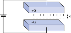
Figure 13.1 (see page 79) shows a parallel-plate capacitor with two plates of equal area, separated by a distance, d. The plates are made of electrical conductors so that charge may flow in and out of each plate. If the capacitor is charged– e.g. by connecting it across a battery as shown – then a charge of +Q will exist on one plate and a charge of −Q on the other. If the battery is disconnected, the charge will continue to be stored on the plates of the capacitor as the positive charge on one plate attracts the negative charge on the other. This is why a capacitor is often described as a device for storing charge. (A large capacitor will retain this charge for a long period of time after it has been disconnected from the source of electromotive force (EMF). For this reason, it should be treated with extreme care as severe electric shock may result from touching the plates or the electrical connections to the capacitor.)
Stay updated, free articles. Join our Telegram channel

Full access? Get Clinical Tree


