General Principles
Cardiac computed tomography (CT) is a specialized form of chest CT. All the technical principles that govern the acquisition and reconstruction of chest CT also apply to cardiac CT. However, the nature of cardiac anatomy and function requires that the system image small, complex structural elements in a rapidly moving organ that often contains a mixture of hard and soft densities. This requires several modifications to the standard chest CT technique. The primary modifications are the use of electrocardiogram (ECG) gating or triggering and special reconstruction algorithms required to generate motion-free images of the moving heart, as well as the use of very thin-slice, high-resolution scanning and reconstruction, which are required to image the small structures of interest and generate an isotropic data set.
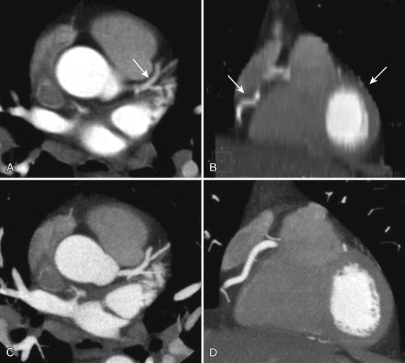
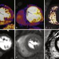
ECG gating truly distinguishes cardiac CT from standard chest CT. ECG gating refers to the monitoring, collection, and use of ECG data before, during, and after the scan acquisition, all of which are needed to achieve the ultimate goal of cardiac CT: motion-free tomographic images of the heart. Gating is required for cardiac imaging because standard chest CT scan acquisition and image reconstruction parameters do not account for the motion of the heart, but are concerned only with image reconstruction in the spatial x-y plane. Standard chest CT does not take into account the timing of the reconstruction relative to any time point within the cardiac cycle. The resultant images of the heart are often blurred by motion artifact and appear in random cardiac contraction phases because although the reconstruction correctly renders where the anatomy is in the x-y plane, it does not take into account when the anatomy relative to the cardiac cycle is rendered. Cardiac reconstruction algorithms use ECG data to parse out the data and reconstruct the images at a single time point within the cardiac cycle, usually late diastole, when the heart briefly comes to rest ( Fig. 3-1 ).

The addition of ECG gating or triggering introduces its own technical limitations and potential problems to the standard CT scan method. In a standard CT scan, the scan mode is either axial or helical. In an axial scan, the gantry, holding an x-ray tube on one side and a detector array on the opposite side (or two such pairs in case of dual source CT), spins around the patient while the table remains motionless. The x-ray tube is turned on (triggered at a predetermined time point of the ECG) over an approximately 180- to 360-degree arc around the patient and then is turned off. As the gantry continues to spin with the x-ray tube off, the table is advanced by an increment approximately equal to the coverage of the detector array and then is stopped. The x-ray tube is again turned on, acquires another arc of attenuation data, and then is turned off, and the table is advanced again. This cycle repeats until the entire desired scan length is covered. Data acquisition occurs in slices that are in the transverse (i.e., axial) plane of the patient’s body. These slices are put together to reconstruct a volume of data.
In a helical scan, the x-ray tube is turned on once at the beginning of the scan as the table begins a continuous translational sliding motion through the gantry. The x-ray tube stays on throughout the duration of the scan as the table continues to move, and once the entire desired scan length is covered, the tube is turned off, and table motion stops. Data collection occurs as one continuous helix around the patient. Transverse or axial plane images are reconstructed by interpolation of this helix of data.
In a cardiac CT scan, the collection of ECG information during the scan is added to this process. The ECG captures the time of occurrence of each QRS complex during the scan and thereby defines the beginning and end of each cardiac cycle. In all scan modes, the ECG information is used during image reconstruction to select a subset of the attenuation data for reconstruction, usually during diastasis. Diastasis is the relatively quiescent period of slow ventricular filling that occurs just before the atrial kick (atrial systole). Usually, only data collected during late diastasis are used, and late diastasis is estimated to occur approximately three fourths of the way through each cardiac cycle. In some cases, the real-time ECG events during the scan are also used to trigger data acquisition and drive the scan (i.e., to turn the x-ray tube on at the beginning of diastasis and off at the end of diastasis). In these cases, the ECG is used to predict, in a prospective fashion, when the next diastasis will occur, and hence this procedure is referred to as prospectively ECG-triggered cardiac CT. In other cases, the x-ray tube is turned on by some other event (e.g., arrival of contrast material in the ascending aorta), and the ECG information is simply collected along with the attenuation data and is used only during image reconstruction. The ECG information is still used, but only after the scan, when it is used to gate the attenuation data (select out the data acquired during diastasis), during the process of image reconstruction. Hence, this procedure is referred to as retrospectively ECG-gated cardiac CT.
The axial scanning method in cardiac CT is always prospectively ECG triggered. The helical scanning method in cardiac CT was the original method of mechanical cardiac CT and is traditionally a retrospectively ECG-gated method. However, one scanner type (dual source CT scanner) can perform a helical scan that is prospectively triggered by the ECG. The ECG information is used to predict when diastasis will occur and then perform an extremely fast helical scan of the heart in that brief instant in time. This procedure requires high table speed and so is referred to as a high-pitch helical scan. (Pitch is a helical CT term that relates table speed to detector coverage. Higher pitch indicates higher table speed.)
Adding the element of ECG gating makes cardiac CT possible, but it also makes the technique vulnerable to gating-related problems and limitations. For ECG gating to work, certain conditions of heart rate and rhythm must be met to provide at least one window of time within each cardiac cycle during which the heart briefly ceases to move, or else the images will be blurred and distorted by motion. Generally, all cardiac CT scan types are trying to reconstruct images in diastasis, so in all cases, if diastasis is too short, or the reconstruction window is too long, then the heart will be moving during some portion of the acquisition, and the resultant images will contain motion, blurring, and artifacts. In addition, ECG-based tube current modulation, ECG-triggered axial scanning, and ECG-triggered high-pitch helical scanning all use the ECG in real time during the scan to turn the x-ray tube on and off, drive tube output, and determine the timing of the actual data acquisition on the fly and so require a regular, steady, predictable cardiac rhythm. Arrhythmia can therefore also result in motion, blurring, and artifacts. In addition, noise and artifacts in the ECG signal itself (e.g., caused by a loose electrode or in a very obese patient) can produce misgating during the scan. Hence, for ECG gating to work ideally, the heart rate and rhythm should be slow and steady, and the scanner should receive a clean, strong ECG signal.
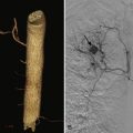
In addition to using ECG gating, imaging of coronary arteries also requires high-resolution thin-slice scanning and reconstruction because of the small size of the structures of interest: normal coronary arteries range in caliber from 5 mm to less than 2 mm. Thin slices are also required to generate an isotropic data set: the cardiac, and especially coronary, anatomy is complex insofar as the arteries are curvilinear and sometimes quite tortuous. Evaluation of this complex anatomy requires visualization and manipulation of the data in all three dimensions, and this is best done using an isotropic data set wherein the z-axis dimension of the voxels is as small as the dimensions in the x- and y-axes, such that each voxel is a cube. Hence, very thin slices, and very thin detector collimation, must be used ( Fig. 3-2 ).
Again, this distinguishing modification of the standard body CT method makes the cardiac technique vulnerable to additional limitations and problems that result from thin-slice image reconstruction. By comparison with standard chest CT (2.5- to 5-mm-thick slices) or even chest CT angiography (CTA; usually 1.25- to 2.5-mm-thick slices), cardiac CT uses extremely thin slices (<1 mm thick); therefore, only small quantities of attenuation data are used for reconstruction of any given slice. At baseline, random fluctuations in the attenuation data are always present: even an image of nothing (air) contains random fluctuations and noise.
Attenuation data derived from imaging structures also contain random fluctuations in their data, or noise, which appear in the image as grain or granularity. The goal of image reconstruction is to map the real fluctuations in the attenuation data produced by the differential radiodensity of adjacent structures and so produce an image of these structures. Image quality depends on the ratio of the amplitude of these real fluctuations to that of random fluctuations. Given a sufficient quantity of attenuation data to feed into the reconstruction algorithm, the degree of noise can be reduced by averaging the data while preserving the real fluctuations from actual structures, thus boosting the signal-to-noise ratio. However, when reconstructing very thin slices by using only a small quantity of attenuation data, less opportunity exists for averaging data and reducing noise, and therefore the signal-to-noise ratio can be low. This relatively larger degree of noise in the image appears as a grainy, noisy image, a consequence of the requirement for very thin sections. This problem is not significant in small or average-weight individuals, but it can significantly limit interpretability in very obese patients.
Finally, the inherent nature of the heart and coronary artery disease may itself pose a problem: calcium and metal within the heart are notorious for degrading image quality in cardiac CT and can obscure visualization of the coronary arteries and reduce diagnostic accuracy. These elements are unavoidable in the cardiac patient population and in some cases may preclude the use of cardiac CT. However, some tools and tricks of the trade are available to compensate for the influence of calcium and metal on image quality, as discussed later.
Hence, the technical considerations of performing cardiac CT include those of any standard chest CT, as well as those particular to cardiac CT. Standard chest CT requires the patient to hold his or her breath during the scan and to cooperate with the scan instructions; the scan needs to be properly timed to achieve optimum opacification of the cardiovascular structures of interest; and a full evaluation of the heart requires the use of intravenous iodinated contrast medium and x-ray radiation. In addition to these requirements, for ideal image quality, a cardiac CT scan yields best results when the heart rate is slow, the rhythm is regular, and no ectopy is present, and the patient should have a reasonable body habitus and, one hopes, a minimal degree of cardiac or coronary metal and calcification.
These modifications to the standard CT technique, the nature of imaging cardiac and coronary artery disease, and the increased potential for technical challenges require special expertise, attention to detail, and the ability to troubleshoot on the part of all those involved in the preparation, performance, and interpretation of these studies. Problem solving is a daily occurrence in a high-quality laboratory striving to achieve the goal of this kind of imaging.
The goal, of course, is to perform the scan in such a way that it maximizes the diagnostic power of the study while exposing the patient to only the minimum amount of radiation necessary to achieve that diagnostic power. Three key elements interplay in every clinical scenario to balance diagnostic quality against radiation exposure: scanner factors, patient factors, and the clinical question ( Box 3-1 and Fig. 3-3 ).
Scanner Factors
Gantry configuration (number of x-ray sources or detector arrays)
Gantry rotation speed
X-ray tube power
Detector configuration (number of rows; row width)
Scan modes
Radiation exposure reduction methods
Reconstruction methods
Patient Factors
Age
Sex
Weight, body mass index, body habitus
Intravenous access
Renal function
Heart rate
Heart rhythm
Blood pressure
Respiratory status (ability to hold breath)
Cognitive status (ability to follow breathing instructions)
Medical and surgical history
Clinical Situation
Indication
Clinical question
Expected impact on patient management
Appropriateness

Key scanner factors include gantry hardware (e.g., number of x-ray tubes), gantry rotation speed, x-ray tube power, detector configuration (e.g., number of detector rows and detector row width), available scan modes (e.g., prospectively ECG-triggered scanning), available radiation exposure reduction methods (e.g., eclipse collimation, ECG-based tube current modulation), and available reconstruction methods (e.g., iterative reconstruction). Key patient factors include age, sex, weight, body mass index, body habitus or shape, intravenous access, renal function, heart rate, blood pressure, respiratory status, cognitive status, and, of course, prior cardiac history.
The clinical scenario is the main indication for the scan It also determines the clinical question, what will be done with the information, and therefore how the scan will be performed.
As an example of the interplay of these elements, consider x-ray tube power. This critical technical specification has significant implications for diagnostic ability and radiation exposure. In knowing this technical specification of the scanner system and understanding its implications, the examiner will quickly realize whether a given patient fits into the technical capabilities of the scanner. For example, imaging the coronary arteries of a very obese patient may be possible if the system has a very strong x-ray tube, but if tube power is insufficient, the study will most likely be nondiagnostic. If that patient also has a high heart rate, then diagnostic imaging will need high temporal resolution, most likely involving the use of the traditional helical scan technique. If the coronary arteries turn out to be normal, the examiner may possibly determine this despite some degradation of image quality by the noise and motion artifact, but if the coronary arteries are heavily diseased and densely calcified, fully evaluating the entire coronary tree for presence and degree of coronary stenosis will be impossible. Moreover, if the clinical question in this patient is whether a 2.5-mm stent contains in-stent restenosis, a cardiac CT scan will probably be able to answer that question, given those scanner and patient factors. Even if it were feasible to image the coronary arteries of the obese patient with a high heart rate and to rule out stenosis if the coronary arteries are normal, this can be achieved today only by using a technique involving high radiation exposure (traditional helical CT). Therefore, if our example patient were a young woman with a low likelihood of obstructive coronary disease who presents with atypical chest discomfort, then it would be prudent to consider other modalities that could answer the question without exposing her to radiation.
Safe, reliable, high-quality cardiac CT will result from understanding what these three key elements (scanner factors, patient factors, clinical scenario) imply and how they interact to define the capabilities, limitations, and appropriate use of this technology. With these general concepts in mind, the next section discusses a few potentially problematic clinical scenarios that may be encountered when performing cardiac CT, the mechanisms behind the problems, and ways to avoid or ameliorate them.
Problem Solving
High Heart Rate
Background
Coronary CTA is one of the most demanding tasks that can be asked of a CT scanner. Not only must the three-dimensional anatomy be imaged, but also all the image data needed for complete image reconstruction must be acquired within the brief instant in time in which the heart is not moving. Fortunately, today’s scanners are exceedingly fast and efficient. However, the speed of cardiac CT is both its beauty and its vulnerability: although the best current scanners can acquire all the data needed for imaging the heart in less than one half-second, it has to be the right half-second. That half-second must contain perfect synchronization of arrival of contrast, settling of the heart into mechanical quiescence, the correct table position relative to the gantry, the appropriate time point within the cardiac cycle, and a good patient breath hold. Part of the trick is fitting the data acquisition within one of the two available moments of cardiac quiescence.
Cardiac Quiescence: End-Systole and Diastasis
The two temporal windows during which the heart may briefly come to rest are end-systole, which occurs during isovolumic relaxation, and late diastole, which occurs after passive filling and before atrial systole (diastasis). The end-systolic window is brief, although it is consistent across a range of heart rates and rhythms. The late-diastolic window is usually longer, although its length is more variable, increasing with lower heart rates and decreasing with higher heart rates. In addition, diastasis practically disappears at heart rates higher than 80 beats/minute, and it is the phase more commonly interrupted by ectopy. Nonetheless, because it is relatively easy to achieve a diastasis that is usually longer in duration than end-systolic isovolumic relaxation, and because of the desire to image the coronary arteries when they are elongated and lengthened, the usual goal is to image the coronary arteries in diastasis. Ideally, then, coronary CTA is performed with a heart rate of 55 to 60 beats/minute, to provide a comfortably lengthy diastasis. The goal of the scan is to acquire all the projection attenuation data needed for image reconstruction within this window of opportunity.
Acquisition Time
The acquisition time is the key scanner characteristic that determines whether the previously stated goal will be possible. It is simply the amount of time required to acquire the attenuation data needed to reconstruct the axial images. As long as the acquisition time is less than or equal to the duration of diastasis, then the heart will remain motionless during data collection, and reconstruction of the collected data will produce motion-free images. If diastasis is too short, or the acquisition time is too long, however, then the heart will be moving during data collection, and the images will be blurred by motion. Acquisition time is determined by several factors, but principal among them are scanner mechanics and scan mode.
The key scanner mechanics elements are the number of x-ray sources and the gantry rotation speed. CT works by collecting attenuation data from multiple view angles around the patient’s body and then using computational algorithms to reconstruct digital representations of the patient’s anatomy. Assigning grayscale values to the numbers then produces an image that the human senses can interpret. Although the earliest scanners used the full 360 degrees of projections for image reconstruction, newer algorithms make it possible to use essentially one half rotation, or approximately 180 degrees of projections, to generate images. Hence, for a standard single source scanner (one x-ray tube and one detector array), the time required to collect all the needed information for reconstruction (i.e., the acquisition time) is approximately one half the gantry rotation time. The fastest single source scanner on the market today spins at 270 msec per rotation, for a nominal acquisition time of approximately 135 msec. For a dual source scanner, the acquisition time is approximately one fourth the gantry rotation time because the two detector arrays (positioned at ~90 degrees to each other on the gantry) cover the arc in half the time. The fastest dual source scanner on the market today spins at 280 msec per rotation, for a nominal acquisition time of approximately 70 msec. The temporal resolution (shutter speed) of the scan is essentially the same as the acquisition time.
Multicycle Reconstruction
In addition to scanner mechanics, scan mode is a key determinant of acquisition time or temporal resolution. In a traditional helical, retrospectively gated cardiac CT scan, temporal resolution can be improved by double or triple acquiring the attenuation data. Today’s detector arrays consist of multiple (32 to 320) rows of detectors. The thickness of each row ranges from 0.5 to 0.625 mm; hence the total z-axis width of the detector arrays ranges from 20 to 160 mm of coverage. This can be thought of as the thickness of the swath of anatomy being scanned by every pass of the gantry.
In helical mode, attenuated photons passing through any given slice level of the patient’s chest strike each of the rows of the detector array in turn as the patient slides through the gantry. If the heart rate is sufficiently high and the table speed is sufficiently slow, not only may the slice be multiply exposed, but also it may be multiply exposed in diastasis. For example, in a scanner with 64 rows of detectors, at a pitch of 0.2, given a heart rate in the 70s or 80s, any given slice of the heart may be imaged in diastasis twice or thrice.
This multiple imaging of the heart can be used to advantage during reconstruction. Rather than reconstructing the images from one single 180-degree arc of attenuation data, the images can be reconstructed from two adjacent 90-degree arcs: the first 90 degrees (e.g., the 0- to 90-degree scan angle) from heart beat 1 and the second 90 degrees (e.g., the 90- to 180-degree scan angle) from heart beat 2. Alternatively, three adjacent 60-degree arcs could be used, again given a high enough heart rate and slow enough table speed.
Because the acquisition of data within each heartbeat is now occurring over a smaller scan angle, the time required for acquisition is shorter: whereas a 180-degree acquisition takes 135 msec, a 90-degree takes 67 msec, and a 60-degree acquisition takes 45 msec. As a result, the temporal resolution improves from 135 msec to, in theory, as fast as 45 msec. This can greatly improve visualization of fast-moving structures, such as valve leaflets and coronary arteries. However, the degree of improvement of the temporal resolution is variable and greatly depends on the exact heart rate. Often, no improvement can be achieved.
The process of stitching these arcs together is referred to as multicycle reconstruction, and in this case, the more beats the better. Multicycle reconstruction is more effective at higher heart rates ( Fig. 3-4 ).

Three caveats should be mentioned. First, radiation exposure is not low. Table speed is slow; the pitch of less than 1 indicates overlapping x-ray exposure; and exposure time is relatively long compared with today’s low-exposure techniques (e.g., axial scanning or high-pitch helical scanning). Second, this technique does not work when the heart and the gantry are in sync (i.e., the cardiac cycle length is a multiple of half the gantry rotation time). For example, if gantry rotation time is 420 msec, then multicycle reconstruction cannot be used for a heart rate of 95 beats/minute, because this represents a cardiac cycle length of 1.5 times the gantry rotation time (630 msec). In this situation, every time the heart returns to diastasis, the x-ray tube returns to the same angular position (or the position directly opposite the gantry); hence the requisite adjacent scan angles can never be collected. Third, multicycle reconstruction requires a regular cardiac rhythm: the heart must behave the same way, come to rest in the same position, with the same cardiac cycle length, from beat to beat, for practically every beat of the scan. If this is the case, results can be surprisingly good ( Fig. 3-5 ). Any variation, especially in cardiac cycle length, during the scan will result in blurring.

Multicycle reconstruction is not limited strictly to helical scanning. A scanner with a wide enough detector array to cover the entire heart in one rotation, such as the 320-row scanner, can perform not just one scan, but two or potentially even three, and again combine these acquisitions to improve the “virtual” temporal resolution. The tradeoff is, of course, that each scan delivers the x-ray exposure of an entire cardiac scan. Therefore, a two-exposure scan delivers twice the exposure, and a three-exposure scan delivers an exposure that reaches the levels of helical scanning, in which case one may as well perform a regular helical scan to accommodate the high heart rate.
Whatever scan mode is used, and whether or not multicycle reconstruction is used, the selected scan and reconstruction methods will result in a particular acquisition time. This acquisition time must fit within the duration of time of whichever cardiac phase (end-systole or late diastole) is selected for acquisition and reconstruction.
A low heart rate (bradycardia) results in a relatively long, motionless diastasis and therefore ample time for data collection to produce crisp, motion-free images. Although some individuals present with such a low heart rate, much more commonly the resting heart rate of the patient is between 65 and 85 beats/minute. Even in patients presenting with a low initial heart rate, anxiety about the scan and the use of sublingual nitroglycerin to increase the size and visibility of the coronary arteries may result in an increase in rate from an initially favorable bradycardia to a more problematic higher heart rate. The high heart rate can be problematic if temporal resolution is insufficient to image the moving structures because this results in motion blurring and potentially a nondiagnostic or poorly diagnostic study.
Different scanners possess differing degrees of capability to compensate for higher heart rates. Some scanners have a limited ability to compensate for high heart rate and are more vulnerable to potential motion artifacts at a heart rate that other scanners can compensate for to produce motion-free images. In general, however, virtually all experts agree that no matter which scanner is used, lower heart rates produce better image results, and for this reason pharmacologic heart rate modulation is usually the first step taken to avoid motion artifact.
Some patients may have a physiologic reason for a higher heart rate (e.g., cardiomyopathy or valvular heart disease). In these patients, lowering the heart rate may be clinically undesirable and even potentially dangerous. Of course, knowing the patient’s medical history and any drug precautions or contraindications is paramount before administering medications. In some cases, the heart rate may remain unfavorable even after pharmacologic manipulation.
Approach to High Heart Rate
The best approach to a high heart rate balances patient factors, scanner factors, and the clinical scenario ( Box 3-2 ). Patient factors may prevent reaching the target heart rate despite administration of the full dose of beta-blocker, or they may preclude using any medications at all.
Related posts:
Stay updated, free articles. Join our Telegram channel

Full access? Get Clinical Tree


