Fig. 13.1
Classifications of atrial septal defect (ASD): (1) secundum type 1, (2) secundum type 2 (red circle), (3) sinus venosus (superior), (4) sinus venosus (inferior), (5) atrioventricular septal (septum primum) defect (green circle), and (6) unroofed coronary sinus. PAPVR partial anomalous pulmonary venous return, SVC superior vena cava, IVC inferior vena cava
Developmental Considerations and Anatomy
In order to understand anatomy and different anomalies of the interatrial septum, it is necessary to be familiar with certain aspects of the atrial septation and the development of the sinus venosus and the pulmonary vein.
Embryology
Around the fourth week of development, the sinus venosus opens into the posteroinferior part of the common atrium in the midline and receives on each side the systemic (common cardinal veins), placental (umbilical), and vitelline (omphalomesenteric) blood by separate paired veins [4–6] (Fig. 13.2). At 5 weeks, the opening of the sinus venosus shifts into the right atrium (sinoatrial orifice) and is guarded by right and left venous valves which unite at the cephalic end of the orifice to form the septum spurium. The pulmonary vein enters the heart as a single structure (common pulmonary vein) with its orifice adjacent to the developing left atrioventricular (AV) junction.
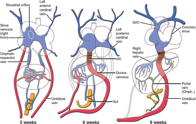
Fig. 13.2
Development of the sinus venosus and omphalomesenteric system. The timing of developments and the relative relationship between structures in cartoons are speculative. IVC inferior vena cava, SVC superior vena cava
The septum primum is also identifiable medial to the left venous valve and just to the right of the orifice of the common pulmonary vein. At 6 weeks, the liver has invaded the omphalomesenteric and umbilical veins, the umbilical veins have lost their connection with the sinus venosus, and the ductus venosus and intrahepatic portion of the inferior vena cava (IVC) are formed. With these changes, the sinus venosus now receives the two common cardinal veins and the IVC, formed by the termination of the right omphalomesenteric vein (Fig. 13.2). These connections result in more enlargement of the right horn of sinus venosus. At this time, the septum primum has begun its growth from the roof of the atrial component, carrying on its leading edge a prominent mesenchymal cap. With time, the mesenchymal cap fuses with the atrioventricular cushions, dividing the AV canal into the prospective tricuspid and mitral valve orifices. The dorsal area of fusion grows into the heart tissue and vestibular spine develops which as it fuses with the primary atrial septum ensures that the pulmonary vein enters the cavity of the left atrium. Soon, the upper margin of the septum primum breaks to form a large secondary interatrial communication (ostium secundum or foramen ovale). In the seventh week, the septum secundum starts to form on the right side of the septum primum but the foramen ovale is still large. The septum secundum is nothing but infolding of the roof between the two atria (interatrial groove). The left common cardinal vein and the left horn of the sinus venosus regress, the latter forming the coronary sinus (CS). The superior vena cava (SVC), IVC, and CS now open into the posterior right atrium and find their final location, the so-called sinus venarum (Fig. 13.2). At 8 weeks, the “septum secundum” develops further. The interatrial groove deepens superiorly to separate the opening of the SVC to the right atrium and the attachments of the right pulmonary veins to the left atrium. The interatrial groove is filled by varying amount of extracardiac adipose tissue and is not a true septum. Its thickness determines the prominence of the fossa ovalis margin at its anterosuperior border. In general at 8 weeks, the incorporation of the sinus venosus into the right atrium and separation of the two atria are complete, and the common pulmonary vein has been taken into the left atrium.
By the ninth week, the left sinus valve disappeared. The residual of the septum spurium can be seen as a prominent trabeculation in right atrial appendage near the superior cavoatrial junction. Remnant of the left sinus valve may be seen on the right side of septum secundum on CT or echocardiography studies. The right venous valve will remain as the Eustachian and Thebesian valves guarding the ostia of the IVC and coronary sinus, respectively. By the 11th week, the right and left pulmonary veins have been taken into the left atrium which then contains four pulmonary orifices. As a reminder, the four pulmonary venous components, with separate orifices on both sides of the left atrial roof, do not achieve their definitive positions until after completion of atrial septation. In other words, the “septum secundum” is only seen at the stage when four pulmonary venous orifices are present.
Arial Septum
The normal atrial septum is made up of the floor and rims of the fossa ovalis, with the superior and posterior rims being infoldings of the atrial walls between the attachments of the caval veins to the right atrium and the ostia of the right pulmonary veins to the left atrium [7] (Fig. 13.3).
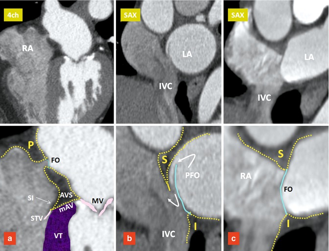
Fig. 13.3
Components of the interatrial septum. Upper row images are four-chamber (4ch) and short axis (SAX) images of three different patients. Lower row images include magnified views of the upper row images. The septum secundum forms the interatrial groove covering the superior (S), posterior (P), and inferior (I) margins of the fossa ovalis (FO). Blue line denotes the septum primum. (a) Small FO with fatty infiltration of the interatrial groove and atrioventricular sandwich (AVS). (b) Shows a patent foramen ovale (PFO). (c) Shows a large FO and a short interatrial groove. IVC inferior vena cava, LA left atrium, mAV muscular AV septum, MV mitral valve, RA right atrium, SI septal isthmus, STV septal leaflet of tricuspid valve, VT ventricular septum
The floor of the fossa ovalis is formed by the septum primum. It is a relatively thin fibromuscular flap that, anterosuperiorly, overlaps an extensive muscular border, also known as “limbus” which is mainly formed by the septum secundum. In at least 70 %, the flap of fossa ovalis is adhered to the limbus. The inferoposterior border of the fossa ovalis continues directly into the wall of the IVC and its anteroinferior border is continuous with the epicardial fat squeezed between the atria and the ventricles at the AV junction (AV sandwich) (Fig. 13.3). The size of fossa ovalis and its margins may vary greatly. If the seal is incomplete, a patent foramen ovale (PFO) will remain at the anterosuperior quadrant of the rim orientated in a craniocaudal, dorsoventral, and right-to-left axis (Figs. 13.3 and 13.4). A PFO has been known to be a very common finding since 1930, when Thompson and Evans identified a “pencil-patent” defect (0.6–1.0 cm in diameter) within the atrial septum in 6 % of unselected autopsies and a “probe-patent” foramen (0.2–0.5 cm) in 29 % [8]. Hagen et al. found a PFO in 27 % of 965 autopsied hearts [9]. The incidence and size of PFO did not differ with gender but varied significantly with age; 34 % of PFOs occurred in the first three decades, 25 % in the fourth to eighth decades, and 20 % in the ninth and tenth decades. The size of the PFO ranged from 1 to 19 mm (4.9 mm, mean) and increased progressively in size from a mean of 3.4 mm in the first decade to 5.8 mm in the tenth decade (perhaps because smaller defects seal with age).
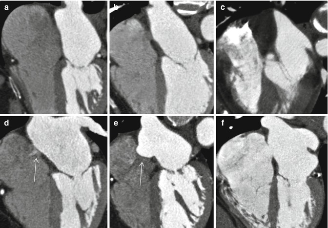
Fig. 13.4
Anatomic variations of the interatrial septum. (a) Straight thin line of septum is seen. No appreciable fat is seen in the interatrial groove. (b) Thickened interatrial groove due to fat accumulation. Fossa ovalis is well demarcated. (c) Severe fatty infiltration of the septum. Fossa ovalis is not seen. (d) Small PFO shunt is shown by arrow. (e) Aneurysm of the atrial septum (arrow). (f) Secundum ASD
Patent Foramen Ovale
PFO is probably the most common cause of right-to-left shunting in patients with paradoxical embolism [10, 11]. It is also an important mechanism by which an embolic stroke can develop in young patients and appears to be more common in larger PFOs [11]. The presence of shunting through the PFO not only depends upon the transatrial pressure gradient but also likely relates to anatomic features of the PFO; these include the size of opening into the right atrium, length of the PFO tunnel, and the extent of excursion of the flap membrane [11–14]. Moreover, the risk of stroke appears to be increased in the presence of structures that direct flow toward a PFO (i.e., prominent Eustachian valve) or hemodynamic changes that increase right-sided pressure (i.e., large pulmonary embolism). In a study performed by Natanzon and Goldman [14], the magnitude of right-to-left shunting was larger and the length of flap valve was shorter in patients with cryptogenic strokes as compared to those patients whose PFO was incidentally found on transesophageal echocardiography (TEE). Similar findings have been reported with cardiac CT. In a recent multi-detector CT (MDCT) study of asymptomatic individuals, 92 % of left-to-right shunts occurred with a PFO tunnel length of 6 mm or less in length [12]. When the flap length is very short, a bidirectional shunt is more probable. Patients with an atrial septal aneurysm (ASA) also have a very short PFO tunnel length. In a recent postmortem study by Ho et al. [13], two types of PFO were described: valve competent and valve incompetent. PFOs with a short, overlapping flap and with an ASA were classified as incompetent with high likelihood of bidirectional flow. Similar morphology has also been described using MDCT in patients with a short PFO tunnel length or those with an atrial septal aneurysm (ASA) [12] (Fig. 13.5).
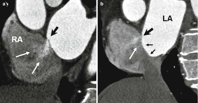
Fig. 13.5
Short axis images show incompetent valves in patent foramen ovale (PFO) with free flow of contrast through the opening (white arrows). (a) The free flap valve is too short to cover the superior rim of the septum secundum (black arrow). (b) Atrial septal aneurysm (small arrows) also demonstrates very short PFO tunnel (large black arrow) causing a left-to-right shunt (white arrow). LA left atrium, RA right atrium
Imaging Modalities in PFO Shunt
Imaging diagnosis of a shunt can be performed directly or indirectly. Direct assessment of an intracardiac shunt is mainly performed by echocardiography and MRI; for extracardiac shunts, CT or MR is commonly performed. Given its wide availability, noninvasive nature, and low cost, echocardiography is currently the most popular. With widespread use of cardiac CT for other indications, it has recently gained momentum for the analysis of intracardiac shunts and PFO. MRI enables direct flow quantification and provides valuable information about size, shape, location, and spatial relationship to other structures [15]. However, the present MRI technique may be inferior to contrast-enhanced TEE in detection of right-to-left PFO shunting (i.e., during Valsalva maneuver) and identification of ASA [15–17]. Although TEE is a great modality to show a right-to-left shunt, most of shunts are positive only after the Valsalva maneuver [18]. Demonstration of a PFO tunnel by MDCT may predict the potential for a shunt. Only a limited number of studies have been performed comparing MDCT to TEE [12, 19]. Current CT techniques for coronary angiography are capable of showing a left-to-right shunt. This can be important as demonstration of a left-to-right shunt, particularly when a short flap valve length or ASA exists, indicates an incompetent valve mechanism with high likelihood of a bidirectional shunt (Fig. 13.5). Furthermore, no provocative test is necessary to demonstrate a left-to-right shunt with MDCT. Current techniques for placement of PFO closure devices rely on fluoroscopic landmarks combined with TEE or intracardiac echocardiography guidance [20]. CT has been used for localization of the fossa ovalis to aid for transseptal catheterization [21]. Given that a PFO is a 3-dimensional (3D) structure with dynamic opening and closing, describing the exact size with one simple dimension is not possible. With CT, scan-detailed 3D information can easily be obtained. CT can accurately demonstrate the relationship of important structures to the PFO including the distance to the aortic root, anomalous coronary artery course, and the location of the coronary sinus ostium. These information may be important before device closure placement [12].
Associated Findings with PFO
Chiari Network
The Chiari network represents coarse or fine fibers in the right atrium, arising from the Eustachian or Thebesian valve and strands within the right atrium connecting these valves with the crista terminalis, right atrial wall, or interatrial septum. It is a remnant of the embryonic right valve of the sinus venosus [22, 23] and should be differentiated from a large Eustachian valve by looking carefully for attachments to other parts of the right atrium. A Chiari network has been reported in 2–4 % of autopsy studies [23, 24] and is generally thought to not be of clinical significance. However, in rare instances, the network may be the site of thrombus formation [25] (Fig. 13.6). In a large study using TEE, a Chiari network was seen in 2 % [26]. Chiari network is frequently associated with a PFO (83 %), right-to-left shunting (55 %), and an ASA (24 %). Fine networks may be difficult to visualize with CT or MRI. With special right heart imaging techniques to clearly opacify the right atrium, a Chiari network may be seen in selected MDCT studies (Fig. 13.6).
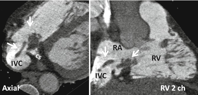
Fig. 13.6
Demonstration of Chiari network with dedicated CT of the right heart. Axial and right ventricle (RV) two-chamber (2ch) view show rounded and band-like structures (arrows) at the inferior cavoatrial junction attaching to the walls of inferior vena cava (IVC) and coronary sinus (CS) ostia. This was confirmed by echo which also showed possible thrombus covering the network. Patient had a history of right ventricle (RV) endocardial pacemaker. RA right atrium
Atrial Septal Aneurysm
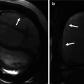
An ASA is another important anatomic feature to consider in evaluating a PFO. The incidence of ASA is 4.6–10 % [27–29] by TEE. An ASA is associated with a PFO with a prevalence of 30–60 % [30–32] and is most likely associated with an increased rate of embolic events [33]. The prevalence of an ASA in patients with cerebral ischemia and normal carotid arteries is higher (28 %) than in patients without cerebral ischemia (10 %) [29]. An ASA can easily be assessed by CT and MRI. In one study with MDCT, an ASA was seen in 4 % of patients, and 63 % of patients with ASA were found to have a left-to-right shunt [12] (Fig. 13.5). An ASA is defined as a bulging of >15 mm beyond the plane of the atrial septum [34] and classified according to Hanley’s diagnostic criteria by Pearson [33] into two types based on the direction and timing of protrusion. Generally, right atrial protrusion is the most common (76 %) and usually shows transient motion toward the left atrium during systole or with the Valsalva maneuver [33] (Fig. 13.7). Increased interatrial septum mobility is believed to enhance the probability of paradoxical embolism by mechanically directing blood flow from the IVC through the PFO into the left atrium.
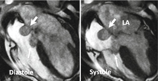
Fig. 13.7
Large atrial septal aneurysm (thick arrows) with persistent protrusion into the right atrium during cardiac cycle. A relatively large membranous septum aneurysm also exists (thin arrows)
Persistent Eustachian Valve in Adults
The Eustachian valve (EV), which guards the anterior-inferior aspect of the IVC, is a remnant of the embryonic right valve of the sinus venosus. Embryologically, the EV directs oxygenated blood from the IVC across the PFO into the systemic circulation [35] (Fig. 13.8). By directing the blood from the IVC to the interatrial septum, a persistent EV may prevent spontaneous closure of the PFO after birth and may, therefore, indirectly predispose to paradoxical embolism. A prominent EV is a common finding in CT or MRI studies of the heart and thorax and should not be mistaken with a thrombus.
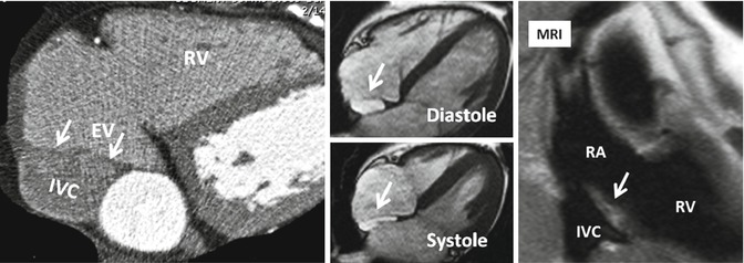
Fig. 13.8
Prominent Eustachian valve (EV) shown on axial CT and MR images (arrows). The EV guards the anterior-inferior aspect of the inferior vena cava (IVC). Note variation in morphology on systolic and diastolic images. RA right atrium, RV right ventricle
Cardiac MR Techniques
In general, MR protocols for intracardiac shunts contain most of the routine sequences. The choice of sequences and extent of coverage depend on the anatomy of interest. For example, in PDA analysis, MR angiography of the great vessels is necessary and the choice of cine and phase-contrast sequences can be individualized. As an another example, the entire chest is covered when looking for partial anomalous pulmonary venous return (PAPVR). An overview of MR protocol is listed below.
Protocol
Positioning
Scout images will be obtained in supine. Table repositioning will be made to place the anatomy of interest (i.e., interatrial septum) at the magnet isocenter.
Morphological Imaging
Two-dimensional axial, sagittal, and coronal images to define cardiovascular anatomy. Both dark- and bright-blood images are acquired with half-Fourier fast-spin-echo and balanced steady-state free-precession (b-SSFP) sequences, respectively. Slice thickness of 6- and 2-mm interslice gap are enough.
Cine Imaging
It is for initial assessment of the intracardiac shunts and analysis of ventricular function. A segmented b-SSFP sequence is used with retrospective ECG gating during repeated 8-s breath holds (slice thickness, 8 mm; no gap). Standard long axis images will be obtained to cover the entire heart from the apex to the atrial base. In our institution, 4-chamber or axial views of the entire heart are obtained in all patients. With a matrix of 256, typical in-plane resolution is 1.7–1.4 mm. Temporal resolution will be 35 ms/phase.
Velocity-Encoded Imaging
Phase-contrast (PC) techniques include direct and indirect assessments of the shunt. Indirect assessment consists of comparing flow in the pulmonary artery (Qp) and aorta (Qs) (Fig. 13.9). Velocity-encoded images are generally acquired using a retrospective vector-ECG gating during repeated expiratory 12–18-s breath holds. Retrospective vector-ECG gating is used in almost all PC MR protocols to include end-diastolic flow. Breath hold technique is preferred to free breathing especially for direct assessment of shunt. For indirect shunt volume measurement, a free-breathing method with multiple measurements (number of excitations = 3–4) can be used to increase precision [36, 37].
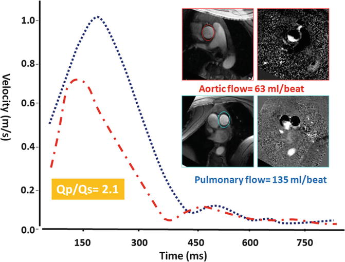
Fig. 13.9
Qp/Qs ratio assessment in a patient with ASD showing 2:1 shunt ratio. Slice position for phase-contrast MRI in the ascending aorta and pulmonary trunk is approximately 2.0 cm above the respected valve
Typical parameters are as follows: slice thickness, 5–6 mm; in-plane resolution, 1.5–2 mm; 18–20 reconstructed heart phases (temporal resolution, 25–30 ms/phase); flip angle 25°; and echo time, 2.8–3.0 ms. Velocity-encoding values differ depending on the anatomy and location and size of shunt. General values include 70–100 cm/s for ASD, 100–200 for VSDs, 100–300 cm/s for PDA, and 150–250 cm/s for arteries.
MR Angiography (MRA)
Three-dimensional gadolinium-enhanced MRA using fast gradient-echo sequence provides further evaluation of any PAPVR. Coronal views are preferred to cover entire heart and major vessels. Alternatively, non-ECG-gated time-resolved MRA can be performed. In case of ASD, 10 mL of gadolinium-based contrast agent followed by a 20-mL saline flush at a flow rate of 5 mL/s will be injected and axial image is obtained. Shunts can be evaluated visually or by analysis of time-intensity curves extracted from measurements within the left atrium, right atrium, and pulmonary vein ostia. This technique has been described for diagnosis of patent foramen ovale during the Valsalva [15]. It can similarly be utilized in selected cases (without or with Valsalva) for diagnosis of other intracardiac shunts. Second alternative is a saturation-recovery gradient-echo sequence commonly used for myocardial perfusion imaging. It will be modified to a non-ECG-gated sequence to acquire continuous data at 6 frames per second during a proper Valsalva maneuver [17] (Fig. 13.10).
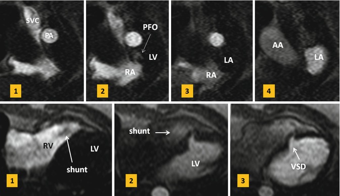
Fig. 13.10
Upper row: first-pass MR angiograms in a patient with patent foramen ovale (PFO). Short axis series during the Valsalva at atrial level show a small puff of contrast (arrow) from right to left at the level of PFO on the third image which disappeared on image 4. Lower row: small muscular ventricular septal defect (VSD) with left-to-right shunt is shown on first-pass MR angiogram. On the first image, non-enhanced blood is passed into the right ventricle (RV). On the second image, contrast-enhanced blood is shunted from the left ventricle (LV) into the right through a muscular VSD. SVC superior vena cava, PA pulmonary artery, RA right atrium, LA left atrium, AA ascending aorta
Shunt Quantification
MR velocity and flow quantification is mainly performed by PC velocity-encoding (VEC) sequences, which elicit contrast from the phase of a spin’s transverse magnetization [38, 39] (Fig. 13.11).
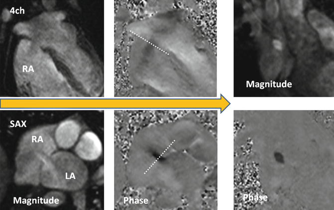
Fig. 13.11
Steps to obtain the optimal imaging plane for en face VEC MR of secundum ASD. It is important to know that the ASD flow direction is not often orthogonal to the plane of the interatrial septum and that the interatrial septum moves during cardiac cycle. To take into account these facts, two orthogonal phase-contrast images along the plane of shunt flow will be obtained. Using these reference planes, final phase-contrast image will be acquired perpendicular to the jet of flow close to the atrial septum and when the shunt flow is maximum. LA left atrium, RA right atrium
TEE usually allows exact localization and sizing of the shunt defect. However, determination of shunt volumes by Doppler echocardiography has limitations [40]. TEE is semi-invasive and might have limitations in visualization of adjacent structures and anomalous venous return. Invasive oximetry using Fick’s principle is the gold standard for the quantification of left-to-right shunting based on measurements of blood oxygenation but is not without limitations [41, 42].
In VEC MR, the phase of flowing protons relative to stationary protons along a magnetic gradient changes in proportion to flow velocity [38]. The change in phase angle is mapped on phase images, and flow velocity is computed with a standard formula. To determine flow volume across a shunt or vessel lumen, the spatial mean velocity of the area of interest is multiplied by the cross section of that area and repeated at each cine frame using automated or semiautomated methods available in most workstations. The region of interest around the blood vessel in each frame may require redrawing for motion and vessel compliance during the cycle. VEC MR imaging flow measurements taken at multiple (usually 16 or 32) evenly spaced points in the cardiac cycle can be plotted against time to construct a flow curve. The area under the curve can be integrated to derive flow volume for a given cardiac cycle.
Technical Considerations
Through-plane flow encoding of the septal defect or a vessel should be assessed in a plane perpendicular to main direction of flow. Underestimation of velocity and flow can result if the target structure is not imaged in a plane perpendicular to flow or if partial volume averaging occurs [43, 44]. Thick slices and volume averaging cause underestimation of flow. The estimation of flow can still be corrected up to 15° deviation from the orthogonal imaging plane. Up to this angle, the increase in vessel area is compensated for by the increase in partial volume effects [43]. Aliasing may occur if the selected velocity-encoding value is lower than the actual peak velocity at any time during the cardiac cycle. Care must be taken not to set the velocity-encoding values too high as this will increase the noise. Noise peaks may interfere with measurement of the peak velocity; however, the estimation of flow is less affected because the noise is averaged over cross-sectional area of the targeted structure [44, 45]. For small vessels, if the vessel diameter is less than 2–2.5 mm (four to eight pixels), accuracy of flow measurements may suffer [46]. Shimming of the magnet before scanning is necessary to compensate for local field inhomogeneity. Faster acquisition is the key to improve phase-offset errors that can occur between bipolar gradients in PC MR. Single breath hold probably causes less artifacts compared to long free-breathing acquisition that may take of 2–3 min. A recent study has shown higher value for pulmonary flow in breath hold technique compared with free-breathing method [47]. Low cardiac output value is expected in retrospective method compared with prospective technique. Therefore, same method should be used for follow-up examinations. In routine practice, the TE is kept short to minimize the time interval in which these phenomena can develop [48]. For technical reason, there is a limit to our ability to shorten the TE to a certain limit. Correct positioning of the patient is another important factor. It would cause less error when the anatomy of interest (i.e., interatrial septum) is placed as close as possible to the magnet isocenter [17]. Phase-offset errors such as those from nonlinear gradients increase with distance from the isocenter. With technological advances in MR imaging, faster data acquisition in single breath hold is possible. Parallel imaging techniques continue to improve and higher acceleration factor can be used in clinical practice. Unfortunately, parallel imaging accelerates acquisition at the expense of a lower signal-to-noise ratio. Therefore, combination with parallel imaging is only recommended when signal-to-noise ratio is not of critical importance for diagnostic image quality.
Aortic and Pulmonary Flow Quantification
VEC MR is an accurate method to measure the amount of shunt. Left-to-right shunting can be calculated indirectly by measuring flow Qp/Qs ration which is the ratio of right ventricle stroke volume to left ventricle stroke volume. For Qp/Qs ratio, VEC MR is shown to correlate well with echocardiography, invasive oximetry, and radionuclide angiography, although this approach does not provide information about the size, shape, or location of a defect [37, 46, 49–53]. Using VEC MR, a 5 % difference between flow in the ascending aorta and flow in the pulmonary artery in healthy individuals is calculated [49, 54]. Therefore, although Qp/Qs measurement by VEC MR may correlate with true shunt severity, this approach is limited when the shunt volume is small. In this case, direct shunt volume measurement is preferred.
Slice position in the ascending aorta is approximately 2.0–3.0 cm above the aortic valve and distal to the coronary arteries at the level of the right pulmonary artery (Fig. 13.9). Slice position in the pulmonary trunk is approximately 1.5–2.0 cm above the pulmonary valve but proximal to the bifurcation. Placing the imaging plane at level of valve should be avoided due to turbulent flow and valve motion. Some have suggested to place the aortic slice at level of coronary artery ostium to include coronary blood flow [55], although this level of slice selection does not seem to be a good choice as the cross-sectional area of the aorta at sinus of Valsalva especially at the level of left main coronary ostium is larger than the aorta above it and may interfere with correct flow calculations. Flow measurements in the ascending aorta distal to the coronary ostia would miss coronary blood flow. For this technical limitation, some have suggested to use Qp/Qs ratios of >1.75:1 as PC MRI threshold for surgery. In reality, diastolic flow into the coronary arteries is minimal (0.5 % of the cardiac output) [56] and even smaller than the errors expected from the PC technique of measurements to cause additional problem. Left-to-right shunts in ASD and VSD are calculated by the following formula: percentage of left-to-right shunt = (Qp−Qs)/Qp. In PDA, it would be (Qs−Qp)/Qs.
Direct Imaging of the Shunt
VEC MR analysis of the outflow tracts is simple, reliable, and straightforward in execution. In a recent study of 35 adult patients with ASD, VSD, and PDA, PC MRI was referenced to transthoracic echo and found to have 93 % specificity and 100 % sensitivity for description of shunts with a Qp:Qs greater than 1.5 [57]. In contrast, direct measurement of shunt flow through the defect requires more experience and precision to get correct results. With direct shunt imaging, flow quantification, as well as size, and morphology analysis are possible which may have incremental clinical value especially for percutaneous closure candidates. The technique of direct en face shunt analysis is described in detail for ASD by Thompson et al. [17] and good correlations with echocardiography in adults were reported. In children, direct flow measurements may be difficult and inaccurate compared with Qp/Qs [37]. This is probably because in children higher heart and respiratory rates, along with higher peak velocities and smaller structures, can lead to increased error on VEC MR [51]. Newer sequences such as 4D phase-contrast sequence can improve visualization of cardiac shunts compared to conventional cardiac MR imaging.
The first step for direct shunt analysis is to review the cine images visually and determine whether flow can be detected (i.e., across the interatrial septum). If shunt is not visible on cine images, still PC images will be obtained at the level of septum to completely rule it out.
Velocity encoding is initially set low (60 cm/s) to ensure sensitivity for lower blood velocities.
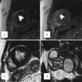
Three contiguous through-plane PC slices will be acquired parallel to the septum with the middle cut in the septum. If the shunt is seen, through-plane VEC MR should be obtained perpendicular to the direction of shunt flow rather than simply perpendicular to the morphological plane of the septal defect [17]. To minimize errors, all phases of cine images will be reviewed and the imaging planes are prescribed at the time when the shunt flow is maximal (i.e., end-systole). Defect area is also measured by planimetry when shunt flow is maximal (Fig. 13.12).
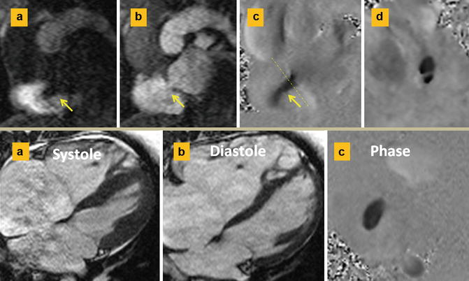
Fig. 13.12
Septum secundum ASD. Upper row: (a and b) are short axis first-pass MR angiographies at the level of ASD. Left-to-right shunt is shown as a negative band in the right atrium in (a). This is best confirmed on phase-contrast image (c). (d) Through-plane phase image shows a double-barrel ASD. Lower row: different case shows ASD diameters change with cardiac cycle. The maximum diameter is usually at ventricular systole (a) when the atria are largest. Smaller length is seen in diastole (b). Typical oval-shaped ASD at the time of maximal flow is shown in the phase image (c)
Classification of Interatrial Communications
Secundum ASD
Secundum ASD is the most common ASD usually seen in middle-aged women [1]. It may be discovered in routine clinical examinations or imaging study of the heart as it is asymptomatic in 90 % of cases. Symptoms include palpitation, atypical chest pain, or those related to paradoxical embolism. Imaging demonstration of morphological variations in size, position, and shape of secundum ASD is important particularly since the widespread use of transcatheter closure techniques. Secundum ASD can be divided into two types depending on location [58]. Type one is the result of abnormal development of the septum primum [59] and is seen in 85 % of cases [58] (Fig. 13.13). In type one, the limbus is intact. The defect is usually oval shaped with a mean size of 1.8–2.8 cm on MR measurements [17]. The size of defect changes with cardiac cycle (Fig. 13.12). The defect area is usually reduced concentrically [60]. The most common location of defect is central with one or multiple holes (fenestrated) [58, 61]. Other variants include complete absence of the flap valve and an anterosuperior defect. Type two is less common (15 %). This type is characterized by abnormal development of the septum secundum or superior limbus of the fossa ovalis resulting in a superiorly located large ASD and an intact septum primum. The atrial roof without any substantial rim forms the superior border of the defect. This is in contrast to superior sinus venosus defects, in which the interatrial communication is located posterosuperior to the normally developed superior limbus. It seems that the two forms of secundum ASD have different pathogenesis.
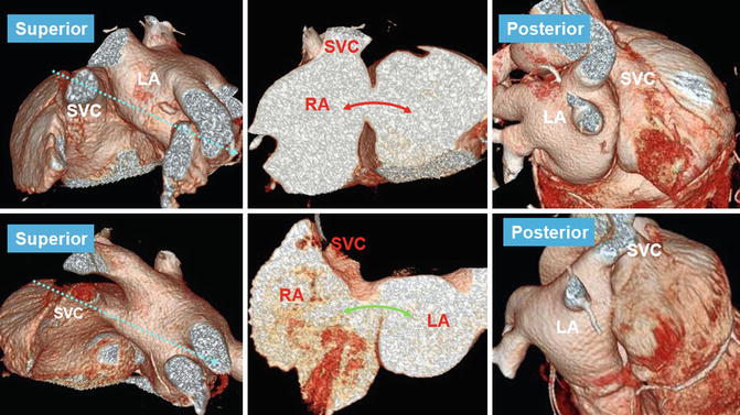
Fig. 13.13
Type 1 (upper row) and type 2 (lower row) of secundum ASD. Anterosuperior views show incomplete development of the interatrial groove in the superior aspect of the septum in type 2 secundum ASD causing a superiorly located defect (curved green arrow) and an intact septum primum compared with type 1 in which the defect is central in the septum primum (curved red arrow) but the superior groove is well formed. Note that posterior groove is relatively well developed in both conditions. Dashed arrows (left images) show the cross-sectional cuts through the ASD shown on the middle images
Sinus Venosus Defects
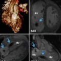
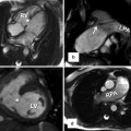
Sinus venosus defects are relatively uncommon forms of interatrial communication (<15 %) [62, 63]. These abnormal venoatrial communications produce shunting between the two atria as a result of anomalous pulmonary venous connection to one of the caval veins (venous-venous malformation) while retaining its connection to the left atrium (Fig. 13.14) or an abnormal vena cava with a large hole at its ostium that overrides the intact rim of the fossa ovalis [64–67] (Fig. 13.15). The caval vein can therefore participate in the formation of a large interatrial communication outside the confines of the fossa ovalis. In other words, this anomaly would be correctly defined as an anomalous venoatrial communication rather than representing an interatrial communication.
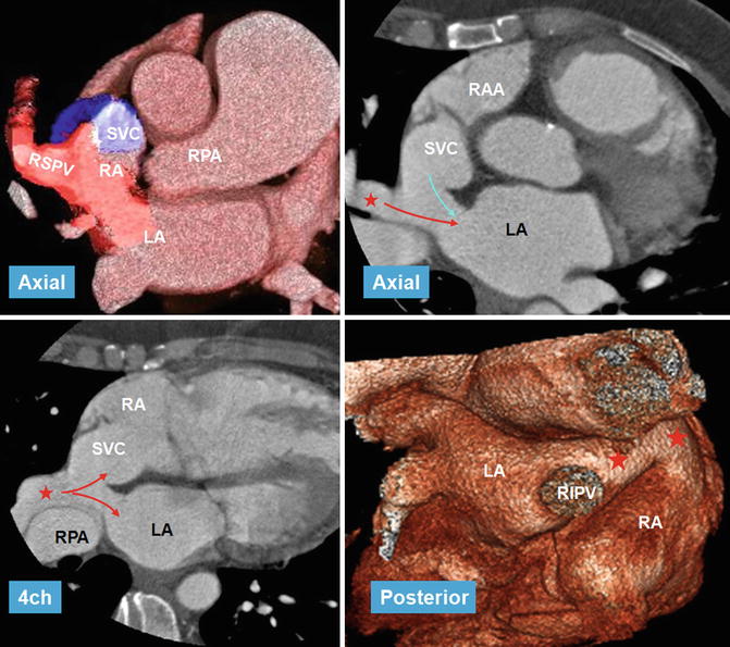
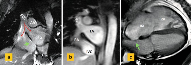
Fig. 13.14
CT images in 56-year-old female referred for evaluation of right heart enlargement and pulmonary hypertension showing sinus venosus defect as a result of anomalous connection of the right superior pulmonary vein (RSPV) (red stars) to the superior vena cava (SVC) while maintaining its connection to the left atrium (LA) (venous-venous malformation). Overriding of RSPV above the septal defect is shown on four-chamber view (4ch). Pulmonary flow (red arrows) and systemic SVC flow (blue arrow) can enter both atria. Posterior volume-rendered view shows RSPV bridging (red stars) between the two atria. LA left atrium, RA right atrium, RIPV right inferior pulmonary vein, RPA right pulmonary vein, RAA right atrial appendage
Fig. 13.15
Sinus venosus ASD in 55-year-old male with right heart enlargement. (a) Short axis cine view and (b) MR angiogram at basal level of the heart show the superior vena cava (SVC) riding over the superior septal defect with blood (red arrows) flowing into both the right atrium (RA) and the left atrium (LA). (c) Four-chamber view shows dilated RA and right ventricle (RV). Intact fossa ovalis is shown by green arrows. AA ascending aorta, IVC inferior vena cava
Two variants are described, superior and inferior. The superior variant is related to the SVC and the inferior variant is in connection with the IVC. The inferior variant is rare and usually diagnosed in children [68]. The crucial anatomic and imaging diagnostic element is the establishment of the integrity of the rims of the oval fossa. Association with PAPVR exists in more than 90 % of cases [69], most commonly involving the right superior pulmonary vein. Involvement of the left pulmonary veins is rare. Abnormal pulmonary venous connections are not a prerequisite for diagnosis and can exist with other types of ASD. It is also possible for the SVC to remain connected to the right atrium only, without any overriding.
Sinus venosus defects may remain asymptomatic until the third or fourth decade of life despite substantial left-to-right shunting [1]. The hemodynamic abnormality is similar to other shuntings between the atria, and it is not possible based on clinical features to differentiate the sinus venosus defect from other forms of interatrial communications [70]. Increased blood flow through the right heart chambers may eventually lead to right ventricular failure. There is threefold greater risk of developing pulmonary arterial hypertension in patients with sinus venosus defects and developing it at younger age than patients with secundum ASD, which highlights the need for correct diagnosis [71].
Accurate demonstration of the abnormal anatomic pathway allows the surgeon either to patch or to baffle the pulmonary and caval pathways to the appropriate atrium without causing obstruction or permitting a residual shunt. Comprehensive imaging diagnosis of sinus venosus defect can be challenging. TEE is superior to the transthoracic approach in adults, with only one-quarter of the defects being correctly diagnosed in transthoracic echocardiography [72]. The majority of diagnostic difficulties arise from the poor acoustic windows. Even with TEE using conventional scan planes, the defect can be missed [73]. Demonstration of PAPVR with TEE is also challenging and in some cases can be frustrating especially for veins that connect to SVC more than 2 cm above the superior cavoatrial junction. Such information is crucial if surgical intervention is being considered. Adult patients with left-to-right shunting and enlarged right heart shown by transthoracic echocardiography should be further evaluated with MRI or CT (Fig. 13.14).
Both CT and MRI are great imaging methods to evaluate these abnormalities particularly for the diagnosis of anomalous pulmonary venous return [74, 75]. It is not uncommon to see a PAPVR with secundum ASD [66]. In an echocardiographic review by al Zaghal [66], 4 of 11 defects initially reported as superior type of sinus venous defect were found to be within the fossa ovalis with abnormal connection of the pulmonary veins to the right atrium in three cases. Therefore, distinction of the septal boundaries is crucial in providing solid criteria for diagnosis. Any problem in formation of superior part of interatrial septum will result in type 2 secundum ASD as described earlier (Fig. 13.13). Communications outside the confines of the true septum can take the form of sinus venosus defects, coronary sinus (CS) defects, and atrioventricular septal defect (AVSD) of “ostium primum” variety [66].
The diagnosis of inferior variant can be more difficult. Again, it is important to find the fossa ovalis rim intact. The Eustachian valve should not be mistaken with inferior border of the defect.
In contrast to superior variant, PAPVR is uncommon in the inferior sinus venosus defect [76], and overriding of the IVC appears to be the cause (Fig. 13.16). If the pulmonary vein participates in abnormal connection to the IVC, then it should continue its normal course to connect to the left atrium [67]. If the pulmonary vein did not maintain normal connection to the left atrium, the IVC would connect only to the right atrium, resulting in partial return to the IVC (scimitar) or the inferior right atrium.
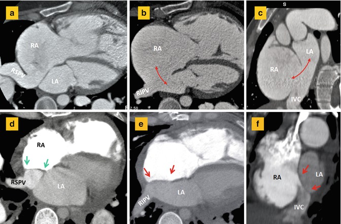
Fig. 13.16
(a–c) CT images before surgery show anomalous drainage of the right superior pulmonary vein (RSPV) into the right atrium (RA) in association with a large atrial septal defect (double-headed arrows) involving inferior aspect of the interatrial septum. Short axis image (c) shows large inferior septal defect and overriding of the inferior vena cava (IVC) over both atria making it difficult to differentiate a large secundum defect from an inferior sinus venosus defect. (d–f) Corresponding after surgery images show closure of the atrial septal defect (between red arrows) and baffling of the RSPV flow (between green arrows) into the left atrium. The right inferior pulmonary vein (RIPV) is normally draining into the left atrium (LA)
Atrioventricular Septal Defect
Detailed AVSD is described in Chap. 17. In AVSD, the atria and the ventricles are separated by a common AV valve with one valve ring [77]. This common valve consists of five leaflets: a superior (anterior) bridging leaflet, an inferior (posterior) bridging leaflet, a left mural leaflet, a right mural leaflet, and a right anterolateral leaflet. A constant imaging feature is loss of normal offsetting of atrioventricular valves. Two morphologies are described, complete and partial [77]. Partial form is more common. In a complete AVSD, one single valve orifice exists. In the partial form, the free margins of the bridging leaflets are fused, creating two separate valve orifices sharing a common valve ring. Unlike a normal two leaflet mitral valve, in partial AVSD, the left AV valve (cleft mitral) has three leaflets. An intermediate or transitional AVSD is also described showing two valves with ASD and VSD. In complete AVSD, there is usually an ostium primum ASD and a large VSD between the common valve and the crest of the interventricular septum. In a partial AVSD, the bridging leaflets fuse to the crest of the interventricular septum, leaving only an ostium primum ASD. They may also fuse with the atrial septum, leaving only a VSD. The potential for left-to-right shunting is related to the bridging leaflets being attached to the atrial septum, to the ventricular septum, or floating within the AVSD [77–80].
Another characteristic feature of AVSD is the anterior and rightward displacement of the aorta in relation to the common AV junction causing an “unwedged” aorta with a narrowed elongated left ventricle outflow tract (LVOT). LVOT elongation creates the characteristic “gooseneck deformity” on left ventriculography and unequal distances from the LV apex to the inlet and outlet valves. Normally, the two distances are equal (Fig. 13.17). Subaortic narrowing/stenosis is particularly notable in partial defects with an ostium primum ASD where the superior bridging leaflet is firmly fixed to the crest of the ventricular septum. Unwedging of aorta can lead to a displacement of the AV conduction tissue and its abnormality.
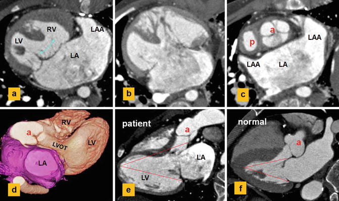
Fig. 13.17
CT images show a single atrium, left atrial isomerism, and dextrocardia. Status post-Fontan and main pulmonary artery exclusion. (a, b) Complete AVSD with a large inlet ventricular septal defect (curved arrow). (c) shows unwedging of the aortic root (a). (d, e) show elongation of the left ventricle (LV) outflow tract (LVOT) causing longer distance of the aortic valve to LV apex compared to the distance from apex to atrioventricular ring. Normally, the two distances are equal (f). (f) Normal example. P pulmonary, LAA left atrial appendage, RV right ventricle
Most primum ASDs are relatively large and lead to right heart dilation. Because of the trileaflet nature of the left AV valve (the so-called cleft mitral valve), valvular regurgitation is common whereas valvular stenosis is rare [78]. A parachute-type or double-orifice “mitral” valve may be present [78]. Complex forms of AVSD are found in the majority of hearts with right atrial isomerism and in around half with left atrial isomerism. The former tends to have univentricular hearts, often with a common atrium, while the latter tends to have biventricular hearts [79] (Fig. 13.17). In atrial isomerism, the common AV valve usually has four leaflets: a large anterosuperior leaflet, two lateral leaflets, and a posteroinferior leaflet [80].
In most patients with AVSD, the ventricles are similarly sized (balanced AVSD). In a minority of cases, the common AV junction is committed to one ventricle leading to hypoplasia of the opposing ventricle. Extreme commitment of the common AV junction to the left ventricle has been termed “double inlet LV with a common valve” [80]. Only a limited number of articles about MR and CT of AVSD exist. In one study of imaging analysis of AVSD, MRI was more accurate than echocardiography in predicting the size of the VSD and diagnosis of ventricular hypoplasia [81].
Related posts:
Stay updated, free articles. Join our Telegram channel

Full access? Get Clinical Tree


