Fig. 8.1
Types of congenital left ventricular outflow tract obstruction. (a) Valvular aortic stenosis. (b) Subvalvular aortic stenosis. (c) Supravalvular aortic stenosis
Valvular LVOTO in the adult patient with congenital heart disease is usually due to bicuspid aortic valve. It usually occurs isolated but can be associated with other abnormalities, the most common being coarctation of the aorta, persistent ductus arteriosus, or aneurysm of the ascending aorta.
Subvalvular LVOTO is usually either a discrete fibromuscular ridge which partially or completely encircles the LVOT or a long fibromuscular narrowing beneath the base of the aortic valve.
Supravalvular LVOTO may occur rarely in isolation as an hourglass deformity. It is more often diffuse, however, involving the major arteries to varying degrees and begins at the superior margin of the sinuses of Valsalva.
Embryology
Valvulogenesis is a complex process during embryonic development whereby a fragile gelatinous matrix is remodeled into thin fibrous leaflets capable of maintaining unidirectional flow over a lifetime. Defective valvulogenesis can result in impaired cardiac function and lifelong complications [1]. A variety of signaling pathways, transcription factors, and genes are involved during valvulogenesis. In the recent years, a large number of genes that play important roles in heart development have been identified [2].
In the outflow tract, mesenchymal cells originating from migrating cardiac neural crest cells will reach the outflow tract cushions and together with endocardially derived mesenchymal cells will contribute to the formation of the aortic and pulmonary valves. Growth factors signal the process of endocardium-to-mesenchyme transformation (EMT) resulting in formation of prevalvular cushions. EMT is followed by a remodeling process whereby mesenchyme differentiates into collagen secreting interstitial valve fibroblasts. This complex process leads to leaflet compaction, attenuation, and formation of fibrous continuities that are indicative of the mature valve tissue (Fig. 8.2). Subtle perturbations in endocardial cushion development can lead to heart valve diseases, including bicuspid aortic valve (BAV) [1, 3].
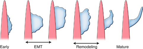
Fig. 8.2
Schematic illustration of valvular morphogenesis. Endothelial-to-mesenchymal transition (EMT) is followed by a remodeling process whereby mesenchyme differentiates to fibroblasts. This process leads to leaflet compaction and mature valve tissue
The morphology of the BAV usually includes leaflets of unequal size as the result of the fusion of two cusps. The larger leaflet is characterized by a raphe, which is a thin ridge of tissue that represents the location where the two cusps fused during valve development. The most frequent BAV subtypes are those with fusion of the right and left (RL) coronary leaflet and those with fusion of the right and noncoronary (RN) leaflet. Insight into the etiology of the RN and RL BAVs was further gained from studies of Nos3 null mice as well as the inbred Syrian hamsters strain which selectively display RN and RL subtypes, respectively. These studies suggested that the BAV-RN is caused by defective formation of the outflow tract cushion, whereas the BAV-RL is likely the result of defective outflow tract septation [4, 5]. Thus, the two BAV subtypes appear to have distinct etiologies.
Imaging Techniques
Cardiac MRI and CT provide highly reproducible and accurate assessments of the structure and function of the left ventricle and valves. They can be used for accurate depiction of complex cardiovascular anatomic and functional features both before and after surgery. The comprehensive evaluation of the LVOT and aortic valve has been expanded. Especially, CT and MRI can be used for accurate morphologic characterization of the aortic valve. MRI can visualize the cardiac structure and function without contrast medium, whereas for CT contrast medium by bolus injection of an iodinated contrast is necessary for adequate analysis of cardiac anatomy.
MRI typically involves ECG gating and breath-hold acquisitions. SSFP (steady-state free precession) sequences allow best functional and anatomic analysis of the cardiac structures and the aortic root. Functional analysis of the left ventricle is usually performed by semiquantitative tracing of myocardial borders by modified Simpson’s rule or newer 4D analysis. SSFP sequences are applied in short-axis, long-axis, and orthogonally angulated views to allow morphologic evaluation of the valve and the LVOT. If information about the velocity of flow across the aortic valve/LVOT is specifically requested, velocity-encoded phase-contrast cine images are acquired perpendicular to aortic blood flow. Comprehensive 4D velocity MRI for visualization and quantification of cardiovascular hemodynamics has been recently developed to understand these pathologies. A delayed contrast-enhanced technique (gadolinium) MRI is usually used to visualize the extent of myocardial fibrosis, especially in left ventricular hypertrophy.
CT with a single breath-hold acquisition allows perfect anatomic images of the whole heart including the LVOT, aortic valve, and aortic root. With advances in CT scanners and software, high-quality 2D reformatted and 3D reconstructed images can be generated to understand the complex cardiovascular anatomy. These scanners generate isotropic data sets with voxels measuring less than 1 mm in the x-, y-, and z-planes. A combination of 2D multiplanar and 3D maximum-intensity-projection and volume-rendered images is most commonly used. Two-dimensional multiplanar reformations can be generated in any plane with resolution comparable with that of axial images. Three-dimensional maximum-intensity-projection and volume-rendered images can be used to display a portion of defined cardiac structures which provides high spatial resolution in all 3 dimensions and thus excellent visualization of the LVOT, aortic valve, and aortic root. Functional analysis with CT is also possible, but this is addressed by increased radiation expose.
Anatomy of the LVOT
CT and MRI provide a clear definition of the LVOT (Figs. 8.3 and 8.4). The LVOT is the region of the left ventricle that lies between the anterior cusp of the mitral valve and the ventricular septum. In the anterior wall are both the muscular and membranous parts of the ventricular septum. The atrioventricular bundle lies at the junction of the muscular and membranous parts of the septum (Fig. 8.5). The posterior wall of the outflow tract is formed not only by the anterior mitral cusp but also by the intervalvular septum and, in its upper part, by a curtain formed by the fusion of the anterior and posterior mitral cusps. The roof of the LVOT is formed by the aortic valve. The LVOT area is not exclusively circular but often assumes a more ellipsoid-like shape. Dynamic changes of the LVOT area during systole are detectable in normal individuals. LVOT is more circular during systole, but the AP diameter remains smaller than the transverse diameter throughout the cardiac cycle. The oval shape of the LVOT has important implications when LVOT area is calculated from LVOT diameters.
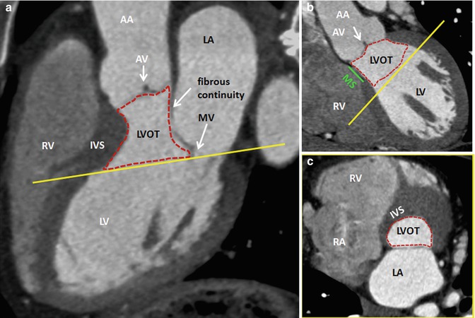
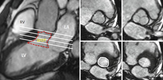
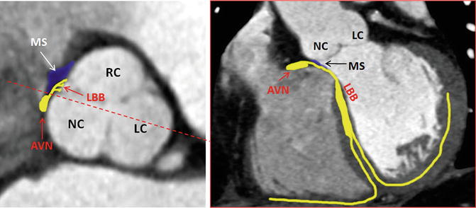
Fig. 8.3
CT of the LVOT and its neighbor structures. (a, b) Long-axis views. (c) Cross-sectional orthogonal view of the basal LVOT (corresponding yellow lines) showing the elliptical shape of the bottom of LVOT. AA ascending aorta, AV aortic valve, IVS interventricular septum, LA left atrium, LV left ventricle, LVOT left ventricle outflow tract, MV mitral valve, RA right atrium, RV right ventricle, MSmembranous septum (green line), Dotted red line delimits LVOT
Fig. 8.4
Short-axis MRI of the LVOT at different levels. LA left atrium, LV left ventricle, LVOT left ventricle outflow tract, RV right ventricle, Red dotted line delimits the LVOT at different levels (white lines), LVOT circumference and diameters are shown in white
Fig. 8.5
Anatomic landmarks of the cardiac conduction system by CT. AVN atrioventricular node, LBB left bundle branch, LC left cusp, MS membranous septum, NC noncoronary cusp, RC right cusp dotted red line in axial view shows the level of coronal plane
Aortic Valve
The normal aortic valve is a trileaflet valve with the left and right cusps giving rise to the left and right coronary arteries, respectively (Fig. 8.6). The noncoronary cusp is in fibrous continuity with the anterior leaflet of the mitral valve. The aortic valve has a semilunar attachment to the junction of the left ventricular outlet and the aortic root. The cusps have a main core of fibrous tissue with endocardial linings on each surface. The cusps are thickened at the midpoint to form a nodule. The area of the aortic orifice in a normal adult is 3.0–4.0 cm2. The imaging plane of the aortic valve to identify the cusps is defined by obtaining long-axis views of the LVOT and the proximal aorta (3-chamber and 2-chamber views). The valvular plane is then obtained by orthogonal views perpendicular to the annulus (Fig. 8.7).
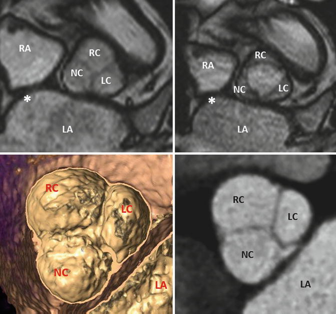
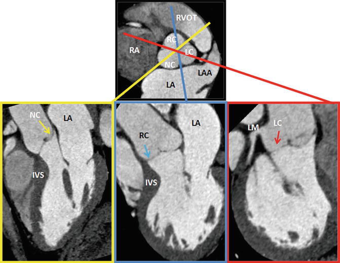
Fig. 8.6
MRI of a tricuspid aortic valve with three cusps during diastole (left) and systole (right). Interatrial septum. Image reconstruction to obtain a cross-sectional multidetector CT image at the level of the aortic leaflet tips. LA left atrium, LAA left atrial appendage, LC left cusp, NC noncoronary cusp, RA right atrium, RC right cusp
Fig. 8.7
Plane selection by CT. From a short-axis image, imaging planes were planned through each of the three cusps of the aortic valve. Left (LC, red), right (RC, blue), and noncoronary (NC, yellow) cusps. IVS interventricular septum, LA left atrium, LC left cusp, LM left main artery, NC noncoronary cusp, RA right atrium, RC right cusp, LAA left atrial appendage, RVOT right ventricle outflow tract
Anatomy of the Ascending Aorta and Aortic Root
CT and MRI allow a detailed understanding of the complex three-dimensional aortic root anatomy, including the crown-shaped anatomic aortic annulus, the virtual basal ring, the sinuses of Valsalva, the valve leaflets, and the sinotubular junction (Figs. 8.8 and 8.9). The ascending aorta consists of the aortic root and the tubular segment [6]. The border between the two is called the sinotubular junction. The aortic root, representing the outflow tract from the left ventricle, provides the supporting structures for the leaflets of the aortic valve and forms the bridge between the left ventricle and the ascending aorta. The top end of LVOT, the aortic annulus, the commissures, the sinuses of Valsalva, the coronary ostia, and the sinotubular junction are the framework in which the valve leaflets are hanging. The annulus is an oval-shaped, 3-pronged coronet with 3 anchor points at the nadir of each aortic cusp [7]. The attachment of the aortic cusps is semilunar, extending throughout the aortic root from the LV distally to the sinotubular junction. The anatomic boundary between the left ventricle and the aorta, however, is found at the point where the ventricular structures change to the fibroelastic wall of the arterial trunk. This locus is not coincident with the basal attachment of the leaflets of the aortic valve.
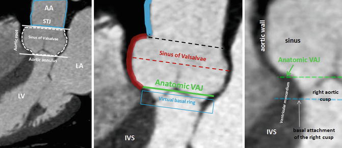
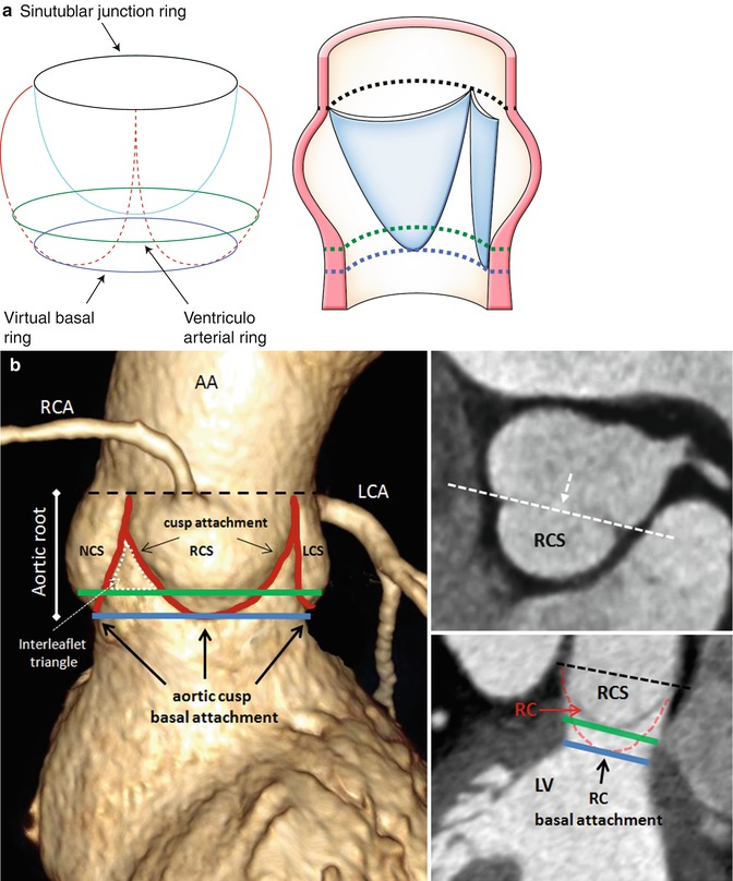
Fig. 8.8
CT of the ascending aorta and the aortic root with its anatomic landmarks of sinotubular junction (STJ) and aortic annulus (delimited by white lines). The aortic root can further be divided in subsegments: the aortic valve, the sinus of Valsalva, (dotted red line) the anatomic ventriculo-aortic junction (VAJ), and the virtual basal ring (blue line). The virtual basal ring represents the level of the basal insertions of the aortic cusps at the left ventricle. The aortic cusps extend from sinusal level through the anatomic VAJ to the virtual basal ring. As shown, the bottom of the cusps sags through the anatomic VAJ. The entire circumference of the AJ and the basal attachment of the aortic cusps can be accurately identified using CT. The green line shows the level of the VAJ with the transformation of the arterial wall into the ventricular wall. The black line shows the STJ. AA ascending aorta, IVS interventricular septum, LA left atrium, LV left ventricle
Fig. 8.9
Schematic representation (a) and contrast volume-rendering CT (b) of the aortic root with its anatomic landmarks. The virtual ring represents the lowest points of attachment of the aortic leaflets into the LV. The semilunar valves extend from the sinotubular junction (STJ) (black line) across the anatomic ventriculoarterial junction (VAJ) (green line) to the virtual basal ring (blue line). This creates a triangle of artery as part of the ventricle between each leaflet (dotted white line). The curved reconstructed CT images show the right coronary sinus (RCS) and sinus in relation to the anatomic VAJ and the virtual basal ring. The two top attachments of the right coronary cusp (RC) are shown, and an angulated view (dotted white line) is reconstructed. This view shows the basal attachment of the right coronary cusp. AA ascending aorta, LA left atrium, LCA left coronary artery, LCS left coronary sinus, LV left ventricle, NCS noncoronary sinus, RCA right coronary artery (A adapted from Anderson [8] with permission)
The root is much wider at the midpoint of the sinuses than at either the sinotubular junction or the basal attachment of the leaflets [8]. This becomes of significance when considering measurements of the annulus because the hinges of the leaflets extend through all these three levels. The appropriate measuring points are at the bottom of the basal valvular attachments, at the widest point of the sinuses, and at the sinotubular junction. Beyond diameter measurements, the perimeter appears especially useful for definition of the exact size in multiplanar CT or MRI. An exact visualization of the aortic root and ascending aorta is important as diseases of these structures are commonly related to bicuspid aortic valve disease and in an interventional and surgical context.
Left Ventricular Systolic Function
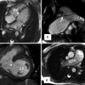
Cardiac volumes and ejection fraction have important prognostic and therapeutic implications in cardiology. Systolic left ventricular ejection fraction is a strong predictor for prognosis in valvular heart disease [9]. Left ventricular end-diastolic volume and end-systolic volume measurement by section summation of contiguous MRI short-axis images is the reference standard for left ventricular function. Cine images in short-axis and two long-axis orientations are used for left ventricular function analysis by guide-point modeling ventricular function analysis (Fig. 8.10).
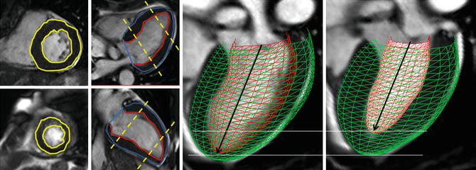
Fig. 8.10
Endocardial and epicardial contours are drawn in short-axis and long-axis views. The contours are drawn in end-diastole and end-systole to calculate left ventricle volumes and ejection fraction. The heart model clearly shows the short-axis contraction compared to the long-axis contraction of the left ventricle
Left Ventricular Mass
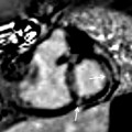
LVOTO results in concentric hypertrophy which is characterized by a reduced end-diastolic radius-to-wall thickness ratio or volume-to-mass ratio (Fig. 8.11). The left ventricular response to LVOTO is complex. It consists of a combination of wall thickening and a change in cavity size with associated effects on systolic and diastolic function. Concentric hypertrophy is defined by a combination of left ventricular hypertrophy and increased relative wall thickness. Patients with LVOTO had wide variation in left ventricular geometry and function [10]. Left ventricular hypertrophy is associated with myofibrillar hypertrophy, but also fibrosis, which is the deposition of collagen and fibronectin. Focal scarring can be observed in severe left ventricular hypertrophy caused by aortic stenosis and correlates with the severity of left ventricular remodeling [11] (Fig. 8.11). The amount of myocardial fibrosis by delayed contrast enhancement is associated with the degree of left ventricular functional improvement and all-cause mortality late after aortic valve replacement in patients with severe aortic valve disease [12].
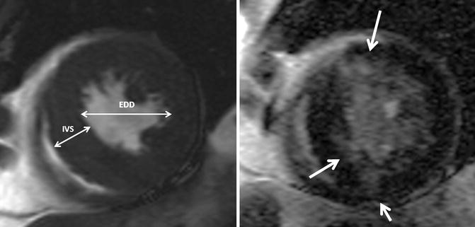
Fig. 8.11
Left ventricular hypertrophy and fibrosis. Short-axis cine and delayed contrast-enhanced cardiovascular MR image show concentric left ventricular hypertrophy and patchy areas of delayed hyperenhancement (arrows), corresponding to myocardial fibrosis. The concentric hypertrophy is characterized by a reduced end-diastolic radius-to-wall thickness ratio (EDD/IVS). EDD end-diastolic diameter, IVS interventricular septum
Valvular LVOTO: Aortic Valve Stenosis
The normal aortic valve is trileaflet. Congenital forms of valve disease are either unicuspid, bicuspid, or quadricuspid. Bicuspid aortic valve is the most common congenital cardiac anomaly occurring in 1–2 % of the population with a male predominance (4:1) [13] (Fig. 8.12). Mutations in the NOTCH-I gene have been related to bicuspid aortic valve. Valve dysfunction in BAV is characterized by an earlier onset and a higher rate of progression in comparison to patients with tricuspid aortic valve disease [14]. Further, BAV has a predisposition to infective endocarditis [15]. Aortic stenosis is the most common complication of patients with BAV [16]. Twenty percent of patients with bicuspid aortic valve have an associated cardiovascular abnormality, such as patent ductus arteriosus or aortic coarctation. Aortic stenosis does not become hemodynamically significant unless the valve area is reduced to approximately 1.0 cm2.
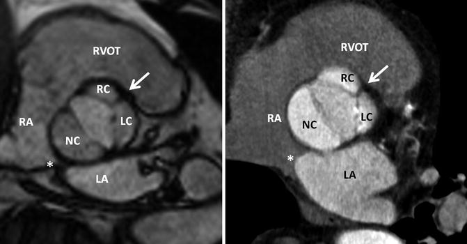
Fig. 8.12
Normal bicuspid aortic valve. MRI and CT of a patient with a bicuspid aortic valve which has three cusps and one raphe (Sievers Type 1 – RL). The fusion of the cusps is between the right (RC) and left coronary cusps (LC) representing a typical thickened raphe (white arrow). The orientation of the atrial septum allows the assignment of the noncoronary cusp. Thus, the noncoronary cusp is always close to the atrial septum. The orifice area is 1.4 cm2 in MRI and 1.5 cm2 in CT, respectively. Interatrial septum. LA left atrium, LC left cusp, NC noncoronary cusp, RA right atrium, RC right cusp, RVOT right ventricle outflow tract
Anatomy and Classification of Bicuspid Valve
Bicuspid aortic valve stands for a common congenital aortic valve malformation with heterogeneous morphologic phenotypes (Fig. 8.13). In general, a purely bicuspid aortic valve has only two cusps and has a characteristic fish-mouth appearance on short-axis images. Histopathological findings, however, show additional phenotypes of the bicuspid aortic valve regarding to the number of raphes, spatial position of cusps or raphes, and the functional status of the valve [16]. Thus, over the past years, different bicuspid aortic valve classifications were described. These classifications, however, are not uniform and easily applicable. Recently, a systematic classification of BAV with respect to the numbers and spatial position of the cusps and raphes, as well as the functional status, was found reliable and appropriate for a classification system from a surgical point of view (Table 8.1) (Fig. 8.14) [17]. By applying Sievers’ classification system, MRI and CT allow excellent characterization of valve phenotype in patients with bicuspid aortic valve for improved management of this entity (Figs. 8.15, 8.16, and 8.17) [18–21].
Get Clinical Tree app for offline access
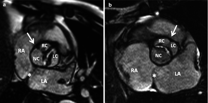
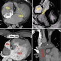
Fig. 8.13
Bicuspid aortic valve. MRI of a stenotic bicuspid aortic valve. (a) Fusion of the right and noncoronary cusps (Sievers Type 1 – RN) and (b) fusion of the right and left coronary cusps (Sievers Type 1 – RL). White arrows indicate the raphe. Note the noncoronary cusp is close to the left atrial septum. LA left atrium, LC left cusp, NC noncoronary cusp, RA right atrium, RC right cusp
Table 8.1
Distribution of BAV phenotype according to Sievers’ BAV nomenclature system
Main category | ||||||||
n | Modality | Type 0 (0 raphe) | Type 1 (1 raphe) | Type 2 (2 raphes) | ||||
Sievers et al. [17] | 304 | intraoperative | 21 (7 %) | 269 (88 %) | 14 (5 %) | |||
117 | MRI | 15 (13 %) | 90 (77 %) | 12 (10 %) | ||||
Kari et al. [21] | 127 | intraoperative/CT | 28 (22 %) | 97 (76 %) | 2 (2 %) | |||
Subcategory | ||||||||
Lateral | Anterior/posterior | RL | RN | LN | RL/RN/LN | |||
13 (4 %) | 7 (2 %) | 216 (71 %) | 45 (15 %) | 3 (1 %) | 14 (5 %) | |||
11 (11 %) | 4 (4 %) | 76 (72 %) | 14 (13 %) | 0 (0 %) | 12 (10 %) | |||
18 (14 %) | 10 (7 %) | 84 (66 %) | 11 (9 %) | 2 (2 %) | 2 (2 %) | |||
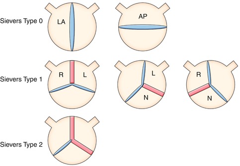
Fig. 8.14
Definition of bicuspid aortic valve (BAV) phenotypes (MRI and CT imaging view) according to Sievers (modified). Sievers Type 0: BAV without raphe, the orientation of the free edge of the cusps defined either lateral (BAV-LA) or anterior-posterior (BAV-AP). Sievers Type 1: BAV with 1 raphe, BAV-RL (fusion of the right and left coronary cusps), BAV-RN (fusion of the right and noncoronary cusps), and BAV-LN (fusion of the left and noncoronary cups). Sievers Type 2: BAV with 2 raphes. L left, R right, and N noncoronary sinuses
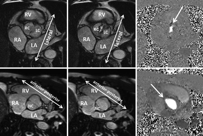
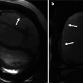
Fig. 8.15
Bicuspid aortic valve Sievers Type 0. Two different patients with cine MRI findings of a bicuspid aortic valve with no raphe. One patient had a stenotic bicuspid (arrow) aortic valve with the free edge of the cusps in the lateral orientation (upper row). The other patient had a bicuspid aortic valve (arrow) with the free edge of the cusps in the anteroposterior orientation (lower row). Additionally, phase-contrast MRI demonstrates clearly the shape of the stenotic and the normal orifice of a bicuspid valve. LA left atrium, LC left cusp, NC noncoronary cusp, RA right atrium, RC right cusp, RV right ventricle
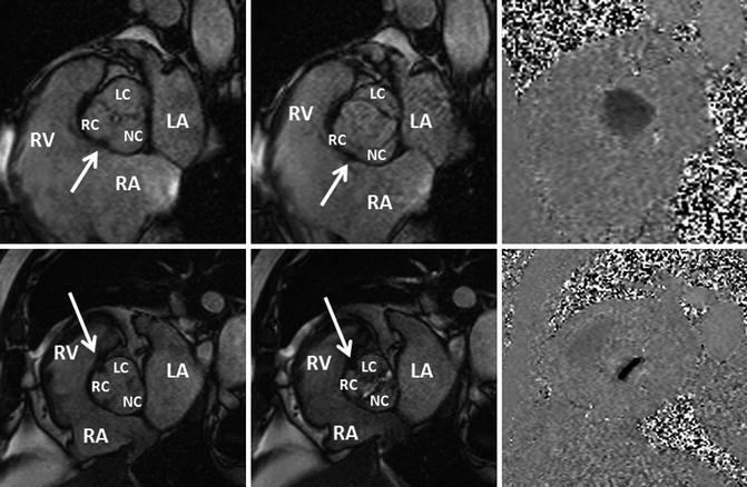
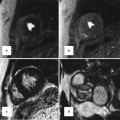
Fig. 8.16
Bicuspid aortic valve Sievers Type 1. Two different patients with cine MRI findings of a bicuspid aortic valve with raphe. The first patient (upper row) had a bicuspid aortic valve with a raphe between (arrow) the right (RC) and noncoronary cusps (NC). The second patient (lower row) had a stenotic bicuspid aortic valve with a raphe between (arrow


Related posts:
Stay updated, free articles. Join our Telegram channel
Full access? Get Clinical Tree
