Central Nervous System Tumors
Yoshiya Yamada
D. Michael Lovelock
Jenghwa Chang
Mark H. Bilsky
One of the hallmarks of radiosurgery is stereotactic localization. In the year 1637, the French philosopher and mathematician Rene Descartes introduced the Cartesian coordinate system for localizing a unique point in three-dimensional (3D) space based on an intersection of three planes,1,2 providing the mathematical basis for cranial and extracranial stereotactic radiotherapy. Robert H. Clarke, an Oxford mathematician, designed a frame that allowed Victor Horsely to accurately place electrodes into a monkey brain in 1908.3 Based on this frame, Spiegel and Wycis introduced the concept of stereotactic localization in humans. Due to the tremendous variability in patients’ anatomy, precise localization using bony reference points was unreliable. Spiegel and Wycis developed a 3D referencing system based on the anterior and posterior commissures of the brain, called stereoencephalotomy, which may represent the first central nervous system (CNS) application of image-guided techniques.4 Lars Leksell, having studied under Wycis, designed a stereotactic frame for functional radiosurgery in 1948. In 1968, Leksell applied the idea to deliver stereotactic radiosurgery (SRS) using the gamma knife. He worked in collaboration with Borje Larsson, a radiobiologist, to create very precise focal necrotic lesions in animals, and later in humans, using single-fraction doses of 100 to 200 Gy.5 The next great advance in the development of radiosurgery was the development of the computed tomography (CT) scanner by Godfrey Hounsfield, a British electrical engineer, which he first used to identify a brain cyst in a human in 1971.6 CT provided the capability to accurately identify brain pathology in three dimensions, greatly expanding the capabilities of SRS to treat brain tumors. Based on stereotactic principles outlined in the 17th century, precise delivery of tumoricidal radiation can be safely administered with local control rates >80% with minimal toxicity.7, 8, 9 Modern radiation therapy treatment planning would be impossible without CT imaging. Continual improvements in imaging technology have increased the application of image-guided stereotactic therapy to almost every site in the human body. Stereotactic radiation has allowed the safe and effective treatment of many devastating and life-threatening tumors for which surgery would carry a high risk or morbidity or mortality.
BIOLOGIC EFFECTS OF HIGH-DOSE RADIATION
Although the exact effects of high-dose, single-fraction radiation on tissue are still not clearly understood, a number of important observations regarding the biologic response to high-dose radiotherapy have been described in classical radiobiology. Large doses of radiation appear to have a more significant impact on slowly proliferating tissues, or “late responding tissues.” Thus, slow-growing tumors and benign lesions such as vestibular schwannomas and meningiomas are more effectively obliterated with high-dose single-fraction radiation.10 Normal tissues, however, benefit from fractionation because the smaller doses per fraction create radiation damage that is easier to repair. In general, the toxicity of radiation is dependent on the inherent radiosensitivity of the treated tissue, the dose per fraction, the total dose given, and the volume of tissue irradiated. Animal data provide insights into the effects of high-dose radiation on neural tissue. Fike et al.11 reported that 15 Gy to the hemibrain of dogs produced necrosis and edema. Radiation doses of 30 Gy were found to cause necrosis within 10 months. Doubling the dose resulted in the same effects within 3 months. When the field size was increased from 7 to 12.5 mm, the effects at high dose were seen significantly sooner (2 months after treatment vs. 6 months after treatment).12 Similar findings have been reported in baboon and cat models, in which demyelination, vascular disruption, and necrosis were noted in a doseand volume-dependent manner. Necrosis is almost universally present in doses in excess of 50 Gy.13,14 It has been postulated that radiation effects on neural tissue can be classified as effects on both the vascular compartment and glial cells. Although large vessels are typically not affected, small vessels manifest blood-brain barrier disruption, resulting in decreased blood flow and ultimately white matter necrosis. Similarly, direct effects on oligodendrocytes cause cell death and demyelination, and the loss of astrocytes results in gliosis.2 The effect of high-dose radiation on the endothelium may be mediated by the sphingomyelinase pathway and subject to a dose threshold effect not seen at doses below 8 to 10 Gy.15, 16, 17
Because radiation-induced myelopathy is one of the most feared complications of radiation therapy, little is known of the true tolerance of the spinal cord to radiation therapy, particularly at high doses per fraction. A recent preliminary report of irradiated pig spinal cord found that single-dose hemicord radiation >20 Gy to the spinal cord resulted in extensive demyelination and white matter necrosis confined to the high-dose region.18 Gibbs et al.19 reported three cases of radiation myelopathy after hypofractionated radiation for spinal malignancies out of 103 lesions treated. The authors concluded that the biologic effective dose (BED) of 58 Gy to
<0.15 cc of the cord, or approximately <12 Gy in a single fraction, is safe.19 In our own experience at Memorial Sloan-Kettering Cancer Center (MSKCC), delivering up to 14 Gy as a maximum dose limit on the spinal cord has not resulted in any cases of myelopathy to date.20 Others have suggested that limiting the cord dose to 10 Gy to <10% of the cord volume is a safe construct to use.21 Although data and experience with high-dose, single-fraction spine radiation is still evolving, it appears that the maximum cord doses in the range of 10 to 14 Gy are safe and reasonable.
<0.15 cc of the cord, or approximately <12 Gy in a single fraction, is safe.19 In our own experience at Memorial Sloan-Kettering Cancer Center (MSKCC), delivering up to 14 Gy as a maximum dose limit on the spinal cord has not resulted in any cases of myelopathy to date.20 Others have suggested that limiting the cord dose to 10 Gy to <10% of the cord volume is a safe construct to use.21 Although data and experience with high-dose, single-fraction spine radiation is still evolving, it appears that the maximum cord doses in the range of 10 to 14 Gy are safe and reasonable.
PRIMARY AND SECONDARY BRAIN TUMORS
Image guidance is especially suited to the treatment of CNS tumors because the tumor is generally fixed in position with respect to nearby bone, which is readily imaged at the time of treatment. The promise of image guidance is the accurate positioning of the target prior to each delivery of radiation, without the need to attach a stereotactic localization frame. For the treatment of extracranial tumors, image-guided techniques have both the potential to safely and accurately deliver high doses of radiation and the ability to deliver the dose shaped to maximize tumor coverage while sparing the spinal cord. This is essentially a new treatment modality; it provides clinicians with tools to consider completely new radiation treatments to tumors that might otherwise have been treated nonconformally to doses limited by the cord tolerance.
The major challenge of the image-guided approach is to meet the exacting spatial accuracy requirements of the delivered dose distribution. This not only involves the target positioning and initial patient setup, but also involves establishing a means of ensuring that the target is correctly positioned throughout the radiation delivery. The latter challenge has been addressed using two different approaches: (a) careful immobilization, sometimes combined with infrared or video surveillance of the patient, and (b) the frequent radiographic localization of the target throughout the radiation delivery, coupled with correction of the beam delivery to account for the observed change in target position. These approaches are discussed in further detail later in this chapter.
Both the dose delivery systems and the imaging systems of the treatment machines vary widely between manufacturers. Delivery systems include conventional C-arm gantries with multileaf collimation; the CyberKnife (Accuray Oncology, Sunnyvale, Calif), a 6-MV linear accelerator (linac) mounted on a robotically controlled arm and equipped with circular collimators; and the TomoTherapy HiArt machine (TomoTherapy Inc., Madison, Wis), a 6-MV linac mounted on a CTlike gantry that delivers the radiation helically using a fan beam. The treatment of small intracranial tumors requires delivery with a collimator that can shape beams with very small field sizes. This will restrict the application of a machine equipped with a multileaf collimator (MLC) with a projected leaf of, for example, 1 cm. In the case of a conventional linac, this can be addressed with the use of an add-on micro-MLC that attaches to the accessory mount; micro-MLCs are in widespread use.22
Imaging systems fall naturally into two groups: dual room-mounted kilovoltage (kV) imagers in fixed positions within the treatment room and gantry-mounted kV or megavoltage (MV) imaging systems. The room-based imaging systems are capable of 3D localization by obtaining orthogonal or near orthogonal radiographs of the target region very rapidly, minimizing any break in the beam delivery process. Even when the gantry position blocks one of the x-ray imagers, it is possible to acquire a single radiograph using the imager with the unobstructed view, allowing at least surveillance of a two-dimensional (2D) view of the target position. The gantry-mounted systems are capable of acquiring each radiograph or MV localization image at any gantry angle, which is useful if the registration is to be done manually. Such systems are generally also capable of acquiring a volumetric image. The TomoTherapy HiArt uses an MV fan beam to generate an MV CT image, whereas the C-arm linacs generate a cone beam image using either the MV beam or the beam from the kV imaging system. Volumetric images can generally be registered with the planning CT using robust automatic techniques that yield accurate information on the setup error, even computing the rotational setup errors.
The volumetric images also contain very detailed geometric information of both bony and soft tissue structures. This is of importance in spinal treatments because the position of critical soft tissue structures such as the esophagus can be localized. 3D treatment images also make possible the calculation of the delivered dose distribution. The strengths and merits of the different beam delivery and imaging systems need to be separately evaluated in the context of cranial and extracranial applications. A few recent articles are discussed.
TOMOTHERAPY: THE HIART MACHINE AND THE PEACOCK SYSTEM
A comparison of treatment plans for single brain metastases with volumes ranging from 437 to 1,840 mm3 between tomotherapy and gamma knife has been reported by Penagaricano et al.23 They found that the tomotherapy plans had larger low isodose volumes but could treat larger lesions than the gamma knife. An earlier study by Meeks et al.24 compared plans for small brain lesions developed by the Peacock tomotherapy system with those developed for a linac-based SRS system. They found similar planning target volume (PTV) coverage, but the conventional SRS approach featured steeper dose gradients outside of the target volume and thus lower doses to organs at risk. Khoo et al.25 compared plans for medium-sized (mean, 85 cm3) brain tumors developed by the Peacock tomotherapy system with those developed for a linac-based SRS system. They found that Peacock plans had slightly better PTV coverage but significantly higher doses to organs at risk because the tomographic approach restricted the beams to transaxial directions.
The use of helical tomotherapy for the re-treatment of spinal lesions using standard fractionation has been evaluated by Mahan et al.26 They reported that the imaging system was capable of positioning an anthropomorphic phantom to 0.6 mm standard deviation in the transverse directions and 1.2 mm longitudinally. Treatments that featured dose gradients of 10% per millimeter were delivered successfully to eight patients. The use of helical tomotherapy, high-dose, hypofractionated or single-fraction spinal treatment has not been reported. The task of monitoring patients for motion during these long treatments would have to be addressed, just as it must be for treatment with a conventional linac.
THE ACCURAY CYBERKNIFE
The CyberKnife is a 6-MV linac mounted on a robotic arm that permits great freedom in the position and direction of the radiation beam. Between 100 and 150 noncoplanar, nonisocentric, cylindrically collimated beams may be used for a spinal treatment. The couch is controlled remotely. Note that beams are predominately anterior; it is not possible to position the linac below the treatment couch. The target is localized using a pair of in-room x-ray imagers. Treatment with the CyberKnife is unique because many 3D localizations, followed by an automatic correction of the subsequent beams using six degrees of freedom in the robotic manipulator, can be performed during the treatment. For a high-dose (24-Gy), single-fraction treatment, 50 such imaging and possible corrective actions may be performed. Patients are typically positioned using alpha-cradle cushions with minimal immobilization. Gerszten et al.27 have reported on the outcome from the treatment of 500 spinal metastases using high-dose (range, 12.5 to 25 Gy; mean, 20 Gy) single-fraction treatments. Patients with tumors in the cervical spine were immobilized using a thermoplastic mask. The imaging system localized the target with respect to skull landmarks. For lower lesions, patients underwent the implantation of four to six gold fiducial markers into the pedicles adjacent to the lesion. No evidence of neurologic injury to the spinal cord was seen. The root mean square (RMS) targeting error of the fiducial tracking technique from all sources—the CT slice spacing, the CT-treatment image registration, and the robot pointing accuracy—has been reported to be 1.0 to 1.2 mm.28 More recently, a tracking system that uses osseous spinal landmarks without the need for implanted fiducials has been used to treat spinal tumors.29,30 Ho et al.29 reported the tracking system error of this technique to be 0.49 ± 0.22 mm.
LINAC WITH GANTRY-MOUNTED IMAGING
The initial image-guided treatments of spinal tumors with a conventional linac were done using the MV portal imager. In two early studies,31,32 patients were carefully immobilized, CT scanned, and then transported on a gurney to the treatment couch. Although the initial intent was to use a stereotactic approach, in one case, MV portal imaging revealed target positioning errors that could sometimes be larger than those planned for, demonstrating the importance of image guidance, even when careful immobilization has been used. Image guidance has also been accomplished using in-room CT scanners.33,34 Although combined linac treatment machines (CT on rails) have been developed and are used for spinal treatment, they have not been widely adopted. Spinal treatment using a pair of MV localization images was in use at MSKCC from 2001 until the advent of gantry-mounted kV imaging in 2005.99,104 Because MV image quality can sometimes be poor, fiducial markers implanted into the spine or the metallic implants from prior surgery were always used to improve the robustness of the manual registration procedure. The addition of onboard kV imaging and kV and MV cone beam scanning capability to existing linacs has greatly facilitated image guidance. Cone beam imaging, although slower, is useful because rotational setup errors are easily identified. However, the problems of patient immobilization and verification that the target is correctly positioned throughout the possibly long treatment session remain. One approach to these problems is to halt the treatment one or more times to check and possibly correct for any shift in target position due to patient motion. This can be done in conjunction with optical or infrared surveillance of the immobilized patient.39 This additional monitoring serves as a kind of early warning system to alert the therapist that there has been a shift in patient position and that the target position should be checked using the kV or MV imagers.
BRAINLAB NOVALIS TX
In-room kV imaging systems are also used in conjunction with gantry-mounted imaging systems. The BrainLab Novalis Tx (BrainLAB, Heimstetten, Germany) treatment machine combines the ExacTrac in-room dual x-ray imagers with a Varian (Varian Medical Systems, Palo Alto, Calif) cone beam-equipped treatment machine. This in-room imaging system can also be added to existing linacs. The ExacTrac system has been used to assess intrafractional motion of immobilized head and neck patients.36 The system is also capable of verifying patient position at any time during treatment by acquiring a single radiograph. Because the gantry may block one of the imagers, verification is accomplished using the imager with the unobscured view. The system can also be used with a robotically controlled couch top, allowing accurate and rapid target repositioning during treatment.
Radiotherapy of primary and secondary brain tumors usually involves whole-brain irradiation, partial-brain irradiation, single-fraction SRS, or fractionated stereotactic radiotherapy (FSRT). Generous margins are usually used for whole-brain or partial-brain irradiation so that the accuracy of conventional radiotherapy setup is sufficient. For SRS and FSRT, however, special immobilization and setup devices (e.g., invasive frame and relocatable frame) are used to meet the more stringent criterion for treatment accuracy. Although the frame system has a high degree of accuracy, it also causes significant pain and discomfort to the patients. Therefore, image-guided radiation therapy (IGRT) has a potential to replace the frame system for patient immobilization and setup of the SRS and FSRT procedures.
One major difference between a frame-based system and an image-guided system is that the frame is both an immobilization and a setup device, whereas the use of IGRT provides only for localization. A separate immobilization device will be needed to restrict patient motion. Therefore, two major physics issues need to be considered when adopting IGRT system for intracranial SRS and FSRT. First, the accuracy of the image-guided setup must be comparable to that of frame-based SRS or FSRT. Second, intrafractional patient movement needs to be evaluated, and if the frequency of clinically significant motion (e.g., >1 mm) is high, a real-time monitoring system needs to be implemented to monitor and correct the intrafractional motion.
Setup and treatment uncertainties of SRS or FSRT can be estimated through an evaluation of the overall accuracy of the planning, setup, and treatment process, which will be referred to here as the inherent system accuracy. The achievable inherent system accuracy of the Brown-Roberts-Wells (BRW) frame-based SRS was 1.33 ± 0.64 mm (mean ± one standard deviation) and 1.2 ± 0.5 mm for 2-mm CT slice thicknesses, as reported respectively by Lutz et al.37 and Yeung et al.39 A more relevant accuracy here is the “apparatus accuracy,” which is the ability of a setup device to position a selected
point at the radiation isocenter. Assuming the only difference between the frame-based system and the IGRT system is the setup and immobilization devices, the IGRT system should have comparable apparatus accuracy as the frame-based system to achieve similar inherent system accuracy. The apparatus accuracy is approximately 0.5 mm for the invasive SRS frame37 and approximately 1 mm for the relocatable Gill-Thomas-Cosman (GTC) FSRT frame.38,39 Although the apparatus accuracy of the relocatable GTC frame is only slightly larger than the invasive frame, large (>2 mm) reposition error was observed for some patients,40 making it unsuitable for SRS procedure.
point at the radiation isocenter. Assuming the only difference between the frame-based system and the IGRT system is the setup and immobilization devices, the IGRT system should have comparable apparatus accuracy as the frame-based system to achieve similar inherent system accuracy. The apparatus accuracy is approximately 0.5 mm for the invasive SRS frame37 and approximately 1 mm for the relocatable Gill-Thomas-Cosman (GTC) FSRT frame.38,39 Although the apparatus accuracy of the relocatable GTC frame is only slightly larger than the invasive frame, large (>2 mm) reposition error was observed for some patients,40 making it unsuitable for SRS procedure.
The 1-mm apparatus accuracy is easily achievable for most IGRT technologies, including kV cone beam CT (CBCT), MV CBCT, MV CT, and fiducial marker tracking. However, it is questionable whether an IGRT system can achieve similar (0.5 mm) apparatus accuracy as the invasive frame system because image-guided setup relies on 2D/3D image fusion and a consistent study of image fusion for SRS remains to be published in clinical situations.41 The matching accuracy depends strongly on the CT slice thickness42 and is generally on the order of a half CT slice thickness. Given that the most commonly used CT slice thickness is 1 to 2 mm for brain scan, the matching accuracy is expected to be poorer than 0.5 mm unless a very thin CT slice (e.g., 0.625 mm) is used.
The uncertainty of the radiation isocenter is another source of apparatus error because the setup apparatus need to be calibrated against the radiation isocenter before patient setup. For a conventional linac system, the calibration usually relies on the intersection of lasers, which has an uncertainty of approximately 0.5 mm. For the CyberKnife system, the linac on the robotic arm moves more freely and has a pointing accuracy of approximately 0.7 mm.43 Considering all these factors, it is very challenging for current IGRT systems to achieve accuracy significantly better than 1 mm until more precise systems are developed.
In addition to a good imaging system, a good noninvasive immobilization device is needed to replace the frame system for patient restriction during the setup and treatment. Patient motion is undesirable (or unacceptable if >1 mm) for SRS treatment. Significant motion during setup CT/CBCT scan also creates artifacts that adversely affect the image-guided setup accuracy. Currently, thermoplastic mask is the most commonly used immobilization device for IGRT because it is less rigid and therefore more comfortable for the patients. Murphy et al.44 studied the intrafractional motion for frameless SRS patients restrained using an AquaPlast mask (AquaPlast Corp., Wyckoff, NJ) and demonstrated that more than half the patients showed a systematic position shift in one or more directions that was at least 2.4 mm, indicating that it was inaccurate to assume that the patient maintained a consistent average position during the SRS treatment, which lasted 30 to 45 minutes.
Therefore, the intrafractional motion needs to be monitored and corrected, and real-time infrared tracking systems45,46 and diagnostic x-ray fluoroscopes47,48 have been developed specifically for this purpose. The intrafractional motion can also be monitored using the on-board kV or MV imager. Ideally, the signal of a monitoring device should be directly fed back to the couch controller so that the patient position can be corrected in real time. However, because most standard treatment couches do not allow such control, many institutions that practice image-guided frameless SRS and FSRT interrupt the treatment if the motion exceeds a preset tolerance (e.g., 0.5 mm) and manually correct the patient position.
In addition to monitoring patient motion during treatment, a real-time position monitoring system also provides information to determine and apply any correctional shifts to treatment table position between table rotations if the treatment table is not well tuned (i.e., its center of rotation precesses). This would be an important feature for treatment setup using an onboard imager that cannot be used at noncoplanar treatment planes.
Depending on the IGRT techniques, additional implanted or external fiducial markers might need to be included in the field of view for the simulation CT scan. Most of the immobilization devices and fiducial markers used for intracranial IGRT are CT compatible, except that some of them are made with high-density material, which might cause streak artifacts and make it difficult to determine the position of fiducial markers or tumor precisely. Magnetic resonance imaging (MRI) compatibility is usually not required for these devices unless MRI simulation is used.
The most important factor for determining the localization accuracy of frame-based and image-guided SRS/FSRT is the CT slice thickness. Because of the finite resolution and slice thickness, the position of an object shown on a CT image can only be accurate within a half pixel size or slice thickness. The effect of imaging uncertainty is usually referred to as “localization error” and is calculated as the difference between the inherent system error and apparatus error in quadrature.37 Because the slice thickness (e.g., 1 to 2 mm) is generally larger than the in-plane resolution (e.g., 0.7 mm) for brain CT scan, the localization error is usually on the order of a half-slice thickness. For example, Lutz et al.37 and Yeung et al.39 studied the accuracy of the BRW frame-based SRS system and reported that the localization error was 1.28 ± 0.71 mm and 0.91 ± 0.3 mm, respectively, for 2-mm CT slice thickness.
Note that the localization error is introduced in the treatment planning process and therefore is common to both frame-based and image-guided systems. The uncertainty due to finite slice thickness also affects the apparatus accuracy for image-guided system because positions of patient anatomy or fiducial markers determined from the simulation CT are compared with those from setup imaging. Murphy42 reported that the position accuracy of the skull for frameless SRS using the stereotactic x-ray fluoroscopes of the CyberKnife system improved by a factor of 2 (mean radial error from 1.2 to 0.6 mm) when the CT slice thickness was reduced from 3.0 to 1.5 mm.
Similar amplification of localization error appears for the optic-guided system. As pointed out by Meeks et al.,49 the setup error using light-emitting fiducial markers increases as a function of fiducial localization error because the positions of fiducial markers on the simulation CT scan are compared with those determined by the infrared camera. This localization error is further amplified as the distance between the fiducial centroid and the isocenter is increased.49 Therefore, in addition to using high CT resolution to minimize the fiducial localization error, the fiducial markers should be positioned as close to the treatment target as practically possible to optimize the setup accuracy.
Frame-based FSRT and SRS traditionally allow a very small PTV margin to reduce doses to critical organs. Therefore, the major question for IGRT treatment planning is whether a similar margin can be used for PTV expansion around the clinical target volume (CTV). Because IGRT has a similar inherent
system accuracy as the relocatable frame, a similar PTV margin as that used for frame-based FSRT should be sufficient for image-guided FSRT. However, a slightly larger PTV margin should be used for image-guided SRS due to its slightly inferior inherent system accuracy. The additional uncertainty should be added in quadrature to the margin currently used for framedbased SRS. For example, 2-mm and 3-mm PTV margins are currently used at our institution for frame-based SRS (BRW frame) and FSRT (GTC frame), respectively. The same 3-mm PTV margin was used when IGRT with 2D kV projection images was adopted to replace the GTC frame for some FSRT patients. We are currently still evaluating the use of kV CBCT-guided frameless SRS, which is estimated to have a PTV margin of mm, assuming that the CBCT-guided setup contributes an additional 1 mm of setup uncertainty.
system accuracy as the relocatable frame, a similar PTV margin as that used for frame-based FSRT should be sufficient for image-guided FSRT. However, a slightly larger PTV margin should be used for image-guided SRS due to its slightly inferior inherent system accuracy. The additional uncertainty should be added in quadrature to the margin currently used for framedbased SRS. For example, 2-mm and 3-mm PTV margins are currently used at our institution for frame-based SRS (BRW frame) and FSRT (GTC frame), respectively. The same 3-mm PTV margin was used when IGRT with 2D kV projection images was adopted to replace the GTC frame for some FSRT patients. We are currently still evaluating the use of kV CBCT-guided frameless SRS, which is estimated to have a PTV margin of
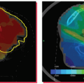
mm, assuming that the CBCT-guided setup contributes an additional 1 mm of setup uncertainty. Figure 17.1. A and B: Two computed tomography (CT) slices are shown for a patient with tumor in the left optical nerve. The planning target volume (PTV) and critical structures (optical nerves, eyes, and chiasm) were also exported with the CT image set. C and D: The image-guided three-dimensional setup is demonstrated by overlaying the cone beam CT (blue) volume on the CT (red) volume. |
Depending on the IGRT techniques, additional information needs to be generated by the treatment planning system for IGRT setup. This information might include the planning CT itself, digitally reconstructed radiographs (DRRs) of the cranium, or relative positions of implanted or external fiducial markers with respect to the treatment isocenter. Most modern treatment planning systems have Digital Imaging and Communications in Medicine (DICOM) RT export capability, allowing the export of the planning CT and/or DRR with contours of PTV and critical organs. Export of fiducial marker positions is not standardized yet and usually requires special software to transfer data from the treatment planning system to the monitoring device.
Figures 17.1A and 17.1B show two CT slices for a patient with tumor in the left optical nerve. The PTV and critical structures (optical nerves, eyes, and chiasm) exported with the CT image set for image-guided setup are also shown on these slices. Figures 17.1C and 17.1D demonstrate the image-guided 3D setup by overlaying the CBCT (blue) volume on the CT (red) volume. The two scans aligned almost perfectly around the anterior portion of the head (the PTV region). However, the alignment was slightly off in the posterior portion due to minor rotation between these two scans. Although the rotational corrections between these left-lateral two volumes could be determined by the setup software, we chose to apply only translational corrections for this case because the rotational errors were not clinically significant.
Figures 17.2A and 17.2B show the PTV overlaid on the orthogonal (anterior-posterior [AP] and LL) DRRs for the same patient, which were exported to the record and verify system to serve as reference images for radiographic guided setup using a Varian OBI system. Figures 17.2C and 17.2D show the AP and LL radiographs that were registered to the exported DRRs for 2D image-guided setup.
Once the patients are properly set up using image guidance, treatment delivery is basically the same as conventional brain radiotherapy except that intrafractional motion needs
to be monitored and corrected. If a monitoring device is not used, additional margin should be used for the PTV expansion to account for the intrafractional motion. However, this may defeat the purpose of image-guided setup, which is to achieve similar setup accuracy as the frame-based system but with improved patient comfort and clinical flexibility.
to be monitored and corrected. If a monitoring device is not used, additional margin should be used for the PTV expansion to account for the intrafractional motion. However, this may defeat the purpose of image-guided setup, which is to achieve similar setup accuracy as the frame-based system but with improved patient comfort and clinical flexibility.
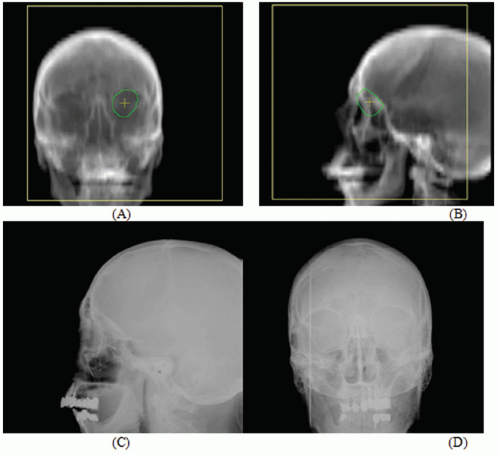 Figure 17.2. A and B: The planning target volume (PTV) is overlaid on the orthogonal (anterior-posterior [AP] and left-lateral [LL]) digitally reconstructed radiographs (DRRs) for the same patient shown in Figure 17.1. These two DRRs were compared with (C) AP and (D) LL kilovoltage radiographs for two-dimensional image-guided setup. |
One major concern for monitoring the intrafractional motion is the frequency of monitoring. This is particularly important for x-ray fluoroscopes because the patients might receive a significant but unnecessary radiation dose if imaged more often than needed. Murphy50 reported that the systematic position shift for frameless SRS patients immobilized using thermoplastic mask is a slow varying function and a tracking interval of 1 to 2 minutes is sufficient to maintain a targeting precision better than 1 mm for most cranial and spine radiosurgery applications. This time interval is also sufficient for setup CT/CBCT scans because these scans usually take about 1 minute, during which time the motion artifacts should have a negligible effect on the image quality.
Real-time infrared tracking systems46 have been used for FSRT for patient setup and monitoring at the University of Florida since 1995.45 This approach45,49 uses multiple infrared emitters attached to a bite block, which is tracked by a stereo camera system mounted to the ceiling of the treatment room. This technology can track a patient’s position in six degrees (three translations and three rotations) of freedom after complex moves, including table rotations and translations, and during treatment delivery.49
The CyberKnife system,47 on the other hand, uses a pair of diagnostic x-ray fluoroscopes to image the patient periodically during treatment delivery. The anatomy (skull) on the acquired radiographs is automatically registered to that on the DRRs derived from the treatment planning CT study. The six degrees of freedom for corrections are then used to guide a 6-MV linac mounted on a robotic arm in real time to align the beam with the treatment target. Similar stereoscopic x-ray imaging has been used to guide conventional linac-based irradiation.48 Like the infrared tracking systems, stereoscopic x-ray imaging can be used for both patient setup and monitoring.
Although on-board kV CBCT provides the most detailed anatomic information for patient setup, patient monitoring using such a device is probably least reliable. The kV imager used for CBCT can only confidently detect three (two translation and one rotation) of six degrees of freedom of motions. In addition, because the kV imager is perpendicular to the MV beam, the most critical view—along the beam direction—cannot be monitored by the kV imager. As a result, a realtime near-infrared or stereoscopic x-ray tracking device is still needed if the accuracy of CBCT setup is to be maintained during the treatment.
Because frame-based SRS has already achieved excellent setup accuracy and local control, it is unrealistic to expect that image-guided setup will significantly reduce PTV margin and dose to critical organs and improve the local control rate. Therefore, the major improvement of IGRT over the frame-based approach will mainly be improved patient comfort and increased flexibility for intracranial SRS. SRS patients immobilized with an invasive frame have to be simulated and treated on the same day, which demands extensive hospital resources (space and staff) for patient stay and monitoring. Generation of a treatment plan within limited time also puts a lot of
pressure on the treatment planning staff. With IGRT, the patients can be simulated and treated on separate days and scheduled like regular radiotherapy patients, except that the treatment time might be longer. The extra days between simulation and treatment also allow for more flexibility to coordinate the workflow for treatment planning and therapy staff.
pressure on the treatment planning staff. With IGRT, the patients can be simulated and treated on separate days and scheduled like regular radiotherapy patients, except that the treatment time might be longer. The extra days between simulation and treatment also allow for more flexibility to coordinate the workflow for treatment planning and therapy staff.
However, there are a few drawbacks that might prevent using image-guided frameless SRS. Even with all of the realtime monitoring systems available for IGRT, the potential patient movement during the beam delivery is still a major concern for image-guided frameless SRS. Unlike fractionated treatment, any dose delivery error for such single-fraction, high-dose treatment is very difficult, if not totally impossible, to compensate. Although IGRT is more flexible, it requires multiple imaging/computation devices and complex networking, is more challenging for accurate patient setup, and requires monitoring of intrafractional movement. In contrast, the invasive frame system is simple, reliable, and efficient. Therefore, the frame-based approach will remain a viable option for intracranial SRS in the near future even if image-guided frameless SRS has gained significant importance in the past few years.
Kamath et al.51


Related posts:
Stay updated, free articles. Join our Telegram channel
Full access? Get Clinical Tree
