Chapter 11 Physics
Gary Ge and Adrian Dawkins
11 Questions and Answers
Question 11.1: If the amplitude of the ultrasound beam is attenuated by a factor of 2 (halved), the intensity will be changed by what factor?
¼.
½.
2.
4.
Answer:
A. Correct. The intensity of an ultrasound beam is proportional to the square of the amplitude.
B, C, D—Incorrect. Intensity is proportional to the square of the amplitude.
Question 11.2: If the operating frequency is changed from 5 to 2.5 MHz, the wavelength will?
Decrease by a factor of 2.
Increase by a factor of 2.
Decrease by a factor of 4.
Increase by a factor of 4.
Answer:
B. Correct. The wavelength of a sound wave is inversely related to frequency in any uniform medium as shown by the equation:
velocity = frequency × wavelength.
A, C, D—Incorrect. Wavelength is inversely related to frequency.
Question 11.3: The “matching layer” within an ultrasound transducer should ideally have a thickness of?
One-fourth the wavelength of the probe’s sound wave.
Half the wavelength of the probe’s sound wave.
Three-fourth the wavelength of the probe’s sound wave.
One wavelength of the probe’s sound wave.
Answer:
A. Correct. The matching layer is used to minimize the large acoustic impedance (AI) mismatch between the transducer’s crystal and the patient’s tissue. Recall that a large AI mismatch between two materials results in very little transmission of sound across the interface of the materials, that is, the sound is largely reflected. Therefore, the matching layer facilitates transmission of sound which is necessary for imaging. The ideal thickness of the matching layer is one-fourth the wavelength, simply because this results in a net cancelation of any interfering sound from the matching layer itself.
B, C, D—Incorrect. The ideal thickness of the matching layer is one-fourth the wavelength.
Question 11.4: Which statement is true?
The thickness of a transducer crystal is half the wavelength of the sound it creates.
The thickness of a transducer crystal is equal to the wavelength of the sound it creates.
The thickness of a transducer crystal is twice the wavelength of the sound it produces.
None of the above.
Answer:
A. Correct. The thicker the crystal, the larger the wavelength and hence the lower the frequency. Recall, f α1/λ.
B, C, D—Incorrect. The thickness of a transducer crystal is half the wavelength of the sound it creates.
Question 11.5: Sound travels faster in muscle than fat. How does a 10-MHz beam change as it travels from fat to muscle?
The amplitude increases.
Frequency increases.
Wavelength increases.
None of the above.
Answer:
C. Correct. According to the equation for the speed of sound (v = f × λ), an increase in speed causes a linear increase in wavelength since the frequency stays the same.
A. Incorrect. The amplitude is not necessarily altered.
B. Incorrect. The frequency stays the same.
D. Incorrect. The wavelength increases.
Question 11.6: If the diameter of an ultrasound transducer is doubled, the focal spot distance will?
Increase by a factor of 8.
Increase by a factor of 4.
Decrease by a factor of 8.
Decrease by a factor of 4.
Answer:
B. Correct. The distance from the transducer to the focal spot is defined by the equation:

where d is the diameter and λ is the wavelength. Doubling the diameter results in a 4-fold increase since (2d)2 = 4d2.
A, C, D—Incorrect. Near field length is related to the square of the diameter of the transducer.
Question 11.7: Which tissue interface results in the largest amount of sound reflection?
Soft tissue/liver.
Air/fat.
Bone/muscle.
Muscle/soft tissue.
Answer:
B. Correct. The acoustic impedance (AI) of air is so small that boundaries with air and any tissue result in nearly 100% reflection of the sound beam. This is why ultrasound gel is required for scanning, as it facilitates some transmission.
A, C, D—Incorrect. Boundaries with air and any tissue result in nearly 100% reflection of the sound beam.
Question 11.8: What change in decibel (dB) is represented by a 50% loss in beam intensity?
0.5 dB.
3 dB.
5 dB.
10 dB.
Answer:
B. Correct. The equation for dB is as follows: dB = 10 log (I/I0) where I0 is the original intensity and I is the new intensity. If there is a 50% loss in intensity then the change in dB = 10 (log 50/100) = 10 (log 0.5) = 10 (− 0.3) = −3. Note that doubling the intensity results in the same dB change, that is, 10 (log 2) = 10 (0.3) = 3. Clearly a negative change indicates a decrease while a positive change indicates an increase.
A, C, D—Incorrect. A halving or doubling of the intensity is reflected by a 3 dB change.
Question 11.9: What is the fundamental frequency of the harmonic mode for an ultrasound exam with a 3-MHz transducer?
3 MHz.
6 MHz.
9 MHz.
12 MHz.
Answer:
A. Correct. The fundamental frequency for harmonic imaging refers to the center frequency of the ultrasound transducer which is 3-MHz in this case.
B, C, D—Incorrect. The fundamental frequency refers to the center frequency.
Question 11.10: What is the typical contrast bubble size for ultrasound imaging?
1 to 5 µm.
15 to 25 µm.
35 to 45 µm.
55 to 65 µm.
Answer:
A. Correct. Contrast bubbles are normally between 1 and 5 µm, about the size of a red blood corpuscle.
B, C, D—Incorrect. Contrast bubbles are normally between 1 and 5 µm.
Question 11.11: Which of the following is not true of microbubble technology?
Once injected, microbubbles remain confined to the vascular compartment until degradation.
Microbubbles typically degrade after 4 to 6 minutes.
The inert gas, within the core of the microbubbles, is excreted via the urinary tract, though not discernible to the patient.
High mechanical index (MI) settings will destroy microbubbles.
Answer:
C. Correct. Microbubbles are injected intravenously and remain within the intravascular compartment until degradation, typically 4 to 6 minutes after injection. The gas within the core of the bubbles is excreted via the lungs. A low MI setting is required to preserve the integrity of the bubbles since high MI settings lead to accelerated degradation.
A, B, D—Incorrect. These statements are true.
Question 11.12: A 6-MHz ultrasound beam is used to produce an image from a structure at a depth of 15 cm within soft tissue. The image is suboptimal and a 4-MHz probe was used to improve the imaging. How much less attenuation is experienced with the 4-MHz probe?
2 dB.
15 dB.
30 dB.
60 dB.
Answer:
C. Correct. Using the rule of thumb that an ultrasound beam is attenuated 0.5 dB/MHz/cm, a 6-MHz beam will be attenuated by 90 dB over the 30 cm (to and fro) journey. A 4-MHz beam will be attenuated by 60 dB. The difference is, therefore, 30 dB. From a practical standpoint, a decrease of 3 dB equates to a weakening of the original beam by 50%. Therefore, the difference of 30 dB equates to a 50% weakening ten times (recall 30 = 3 × 10).
A, B, D—Incorrect. An ultrasound beam is attenuated 0.5 dB/MHz/cm.
Question 11.13: While traveling through which of the following materials does ultrasound experience the most attenuation?
Soft tissue.
Lung.
Bone.
Muscle.
Answer:
B. Correct. Lungs have the highest attenuation coefficient for tissue of around 40 dB/cm for a 1-MHz beam, followed by bone which is approximately 20 dB/cm. Other tissues are generally close to 1 dB/cm.
A. Incorrect. This is generally closer to 1 dB/cm.
C. Incorrect. Lung typically has the highest attenuation coefficient of around 40 dB/cm for a 1-MHz beam, followed by bone which is approximately 20 dB/cm.
D. Incorrect. This is generally closer to 1 dB/cm.
Question 11.14: Which of the time gain compensation (TGC) curves is associated with highest transducer frequency?

1.
2.
3.
4.
Answer:
D. Correct. The highest transducer frequency experiences the largest attenuation in a propagating medium, thus requiring the value of the TGC to be larger in order to accurately compensate the loss of signal intensity. Curve 4 demonstrates this correctly as it has the steepest TGC increase and the increase begins at the shallowest depth.
A, B, C—Incorrect. These are not associated with the highest transducer frequency.
Question 11.15: Reverberation artifact may be eliminated by changing which parameter?
Transducer frequency.
Transducer orientation.
Time gain compensation.
Pulse repetition period.
Answer:
B. Correct. Reverberation artifact is caused by two closely spaced interfaces that reflect sound back and forth during the acquisition of signal. Since specific angles create the artifact, it can often be eliminated by changing the transducer orientation.
A, C, D—Incorrect. These measures would not be effective in removing the artifact.
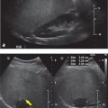
Question 11.16: The scanning scenario (a) results in image (b). What accounts for the difference?

Suboptimal lateral resolution.
Suboptimal axial resolution.
Suboptimal receiver gain.
None of the above.
Answer:
B. Correct. The axial resolution is a measure of the system’s ability to separate two closely positioned structures along the same vertical scan line. The axial resolution improves with increasing transducer frequency.
A. Incorrect. The lateral resolution is a measure of the system’s ability to separate two closely positioned structures lying side by side. The lateral resolution improves with decreasing beam width.
C. Incorrect. Increasing the receiver gain will brighten the displayed image but not improve the signal-to-noise ratio or resolution.
D. Incorrect. The axial resolution improves with increasing transducer frequency.
Question 11.17: An ultrasound image is showing up too dark on the monitor. What adjustment to the scanning parameters should be made first to fix the issue?
Increase output power.
Increase receiver gain.
Decrease output power.
Decrease receiver gain.
Answer:
B. Correct. Increasing receiver gain and output power will both increase the brightness of the image, however adjusting the receiver gain is preferable because increasing output power will deposit more energy within the patient.
A. Incorrect. Increasing the output power would deposit more energy within the patient and is therefore not the best choice.
C, D—Incorrect. These measures would worsen the appearance.
Question 11.18: While performing an ultrasound of the right upper quadrant, the technologist notices a rounded hyperechoic focus above the diaphragm. What should he do next?

Change the angle of insonation.
Scan the other lung.
Turn up the overall gain.
Scan both kidneys.
Answer:
A. Correct. The finding above the diaphragm is a result of mirror artifact and characterized by a mirrored object about a strong reflector, in this case the lung–diaphragm interface. Changing the angle of insonation may help mitigate against this phenomenon.
B, C, D—Incorrect. These measures would not be effective in removing the artifact.
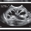
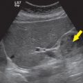
Question 11.19: A longitudinal view of the abdominal aorta is demonstrated below with a color Doppler overlay. What accounts for the two blue regions?

Hypertension.
Flow reversal.
Aortic stenosis.
None of the above.
Answer:
D. Correct. The blue region to the right of the screen, within the more distal aorta, produces a negative Doppler shift based on its orientation with the probe, as it arches away. Notice that the change from red to blue goes through “black” which indicates a true change in direction with respect to the angle of insonation. The blue region to the left of the screen occurs because this segment of the aorta is deeper and hence overwhelms the pulse repetition frequency (PRF), resulting in aliasing. Aliasing represents a misrepresentation of flow direction due to an inadequate sampling rate. Notice that the change from red to blue goes through “white” when aliasing occurs.
A. Incorrect. This does not account for the findings.
B. Incorrect. This does not completely account for the findings.
C. Incorrect. This does not account for the findings.
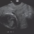
Question 11.20: Where is the beam narrowest?

A.
B.
C.
D.
Answer:
B. Correct. Marker B is positioned at the depth of the focusing bar (“I”-shaped icon to the right of the image). This indicates the “waist” of the beam, where the focusing is optimized.
A, C, D—Incorrect. The beam is narrowest where focusing is optimized.
Question 11.21: How long did it take for position D to be interrogated by the sound beam? Refer to the image in (Question 11.20).
130 µs.
230 µs.
360 µs.
490 µs.
Answer:
A. Correct. Marker D is positioned at a depth of 10 cm. In imaging, sound typically takes 13 µs to make a 1 cm to and fro roundtrip. Therefore, at a depth of 10 cm, the round-trip would take roughly 130 µs.
B, C, D—Incorrect. The round-trip would take roughly 130 µs.
Question 11.22: Regarding pulse wave imaging, the duty factor is?
The percentage of time that the bean is “on.”
The duration of a pulse.
The duration between two pulses.
The number of pulses per second.
Answer:
A. Correct. The duty factor describes the percentage of time that the transducer is emitting sound waves as opposed to receiving sound, during pulse wave imaging. It is frequently expressed as a percentage.
B. Incorrect. The duration of a pulse is the actual time the beam is on for each pulse (in µs).
C. Incorrect. The duration between pulses is the termed the “listening time.”
D. Incorrect. This describes the PRF.
Question 11.23: Cavitation is more likely to occur in which of the following ultrasound examinations?
Two-dimensional imaging using harmonics.
Three-dimensional imaging.
Pulse wave Doppler.
Continuous-wave Doppler.
Answer:
D. Correct. Continuous-wave Doppler produces the highest beam intensity with a “duty factor” of 100%. The duty factor is the percentage of time that the beam is “on” meaning the rate of energy deposition can be much higher than any other imaging technique.
A, B, C—Incorrect. Continuous-wave Doppler produces the highest beam intensity and hence is more likely to cause cavitation.
Question 11.24: Which of the following ultrasound examinations would result in the greatest rise in temperature?
Scanning a prostate.
Scanning a kidney.
Scanning a fetus.
Scanning a bladder.
Answer:
C. Correct. Ultrasound examinations of anatomy containing tissue–bone interfaces have the largest thermal index (TI). Obstetric scanning is therefore most susceptible.
A, B, D—Incorrect. Ultrasound examinations of anatomy containing tissue-bone interfaces have the largest TI.
Question 11.25: While performing an abdominal ultrasound scan, the transducer accidentally falls to the floor. The transducer is retrieved, cleaned, and scanning is resumed. However, soon after, the technologist notices a slender crack within the casing. What action should be taken?
The technologist should stop scanning immediately and switch to a replacement transducer if available.
The technologist can safely complete the scan but should avoid placing gel directly within the crack.
The technologist should listen for any audible ringing, as this could indicate imminent over-heating which could pose a risk to the patient.
The technologist should apply a probe cover and continue with the study.
Answer:
A. Correct. Patients undergoing diagnostic ultrasound examinations come into physical contact with electronic components of the machine including the cables and transducers. Under normal operating conditions, the transducer poses the greatest risk of exposing patients to electrical hazards. If the transducer casing is cracked, the sonographer should stop using it immediately since a cracked transducer casing may lead to electrical injury.
B, C, D—Incorrect. These actions would be inappropriate.
Question 11.26: A technologist is about to begin a pelvic scan utilizing a transvaginal probe. Prior to use, the transducer should be?
Sterilized using dry heat.
Sterilized using moist heat.
Disinfected using a chemical agent.
Disinfected using clean water.
Answer:
C. Correct. Transducers are typically disinfected between patients. This is typically achieved with a liquid disinfectant applied via wipes or immersion. Endocavitary probes should undergo high-level disinfection between patients. Transducers are not sterilized.
A, B—Incorrect. Heating a transducer may damage the piezoelectric elements. Also, transducers are not typically sterilized between patients.
D. Water does not adequately disinfect.
Question 11.27: The Curie temperature or Curie point of piezoelectric materials is in the range of?
100 to 200°C.
200 to 300°C.
300 to 400°C.
400 to 500°C.
Answer:
C. Correct. The Curie point of the piezoelectric materials within ultrasound transducers is generally around 360°C. Beyond this temperature, the material becomes depolarized and loses its piezoelectric properties.
A, B, D—Incorrect. The Curie point is generally around 360 °C.
Question 11.28: Side lobe artifact occurs when?
Offaxis energy encounters a strong reflector.
Offaxis energy encounters a weak reflector.
Sound waves are repeatedly reflected between two highly reflective surfaces.
Sound waves are repeatedly reflected in a tetrahedron of air bubbles.
Answer:
A. Correct. In addition to the main axis beam, radial expansion of piezoelectric crystals creates low energy off axis beams, described as side lobes. If this off axis beam encounters a strong reflector, it may generate an echo that is received by the transducer and artifactually placed along the axis of the main beam. Side lobe artifact is usually encountered in anechoic structures such as the urinary bladder and gallbladder and most commonly seen with linear array transducers.
B. Incorrect. A strong reflector is required.
C. Incorrect. This describes reverberation artifact.
D. Incorrect. This describes ring-down artifact.
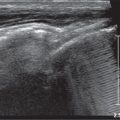
Question 11.29: How could the artifact in the image below be minimized?

By increasing the frequency of the transducer.
By increasing the receiver gain.
By using spatial compounding.
By using harmonic imaging.
Answer:
C. Correct. The image shows posterior acoustic shadowing from a gallbladder calculus. The calculus attenuates sound to a greater degree than the surrounding structures, therefore the intensity of the beam distal to the calculus is weaker than the surrounding field. The attenuation worsens with increasing frequency. Shadowing decreases with spatial compounding and using multiple focal zones.
A. Incorrect. Shadowing worsens with increasing frequency.
B. Incorrect. This does not specifically affect the degree of shadowing.
D. Incorrect. Harmonic imaging results in better visualization of acoustic shadows.
Question 11.30: What accounts for the difference in the measured velocity within these two images obtained from the same patient during the same scan?

Angle of insonation.
Angle correction.
Beam focusing.
Color gain.
Answer:
B. Correct. The Doppler equation (below) reveals the inverse relationship between measured velocity (vel) and the cosine of the angle on insonation (cos θ). The machine must be “told” the angle at which the vessel is oriented while being interrogated. This is done by manually “correcting” the angle by aligning the angle indicator with the plane of the vessel. This is done fairly accurately in image (a) but over-estimated in image (b). Overestimating the angle results in an overestimation of the velocity since as θ increases from 0 to 90 degrees, cos θ decreases, making the denominator smaller and hence the velocity larger.
C × fDop = vel f0 × 2 × cos θ
A. Incorrect. The angle of insonation, that is, where the probe is positioned on the patient, is fairly constant across images (a and b).
C. Incorrect. This is fairly constant across images (a and b).
D. Incorrect. This is fairly constant across images (a and b).
Related posts:

Stay updated, free articles. Join our Telegram channel

Full access? Get Clinical Tree


