and Vincent L. Sorrell2
(1)
Division of Nuclear Medicine and Molecular Imaging Department of Radiology, University of Kentucky, Lexington, Kentucky, USA
(2)
Division of Cardiovascular Medicine Department of Internal Medicine Gill Heart Institute, University of Kentucky, Lexington, Kentucky, USA
Electronic supplementary material
The online version of this chapter (doi: 10.1007/978-3-319-25436-4_7) contains supplementary material, which is available to authorized users.
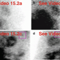
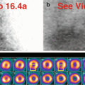
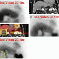
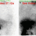
During SPECT MPI, there are a myriad of reasons for “hot” and “cold” artifactual and potentially misleading imaging findings related to the chest wall (Table 7.1). Troubleshooting of “hot” and “cold” findings should be undertaken in conjunction with the performing technologist. “Hot” artifacts may be related to contamination on the patient (Fig. 7.1). If the patient’s arms are positioned along the chest wall and within the field-of-view, extravasation at the injection site will produce a characteristic focal “hot” region that might create scatter artifact (Fig. 7.2) (Hendel et al. 1999). Nearby radioactive sources emitting photons from another patient or a prepared syringe may be registered on the gamma camera detector during MPI (Fig. 7.3). On review of the raw projection data, blood, injectate, or urine contamination should be superficial, not deep (Hendel et al. 1999). If skin or clothing contamination is suspected, the technologist should ask the patient to wash and change clothing, and the patient should be re-imaged (Gentili et al. 1994; Williams et al. 2003). Analogously, the gamma camera detectors should be routinely checked for contamination and cleaned as necessary before use (Burrell and MacDonald 2006; Chamarthy and Travin 2010; Gedik et al. 2007). Mal-administration of the radiopharmaceutical inadvertently using an arterial instead of a venous access can produce an unusual muscular biodistribution (Afzelius and Henriksen 2008). Radiopharmaceutical-avid brown adipose tissue (BAT) may be present in the supraclavicular regions of the anterior chest wall or in a posterior paraspinal location (Goetze et al. 2008).


Table 7.1
Differential diagnosis of “hot” and “cold” imaging findings related to the chest wall
Organ system | “Hot” finding | “Cold” finding | References |
|---|---|---|---|
Chest wall | Brown adipose tissue Shoulder/upper chest skeletal musculature (due to arterial injection) Contamination (radiopharmaceutical, urine) Cross talk from nearby radioactive source (another patient on treadmill) | Soft-tissue mass Internal metal objects (pacemaker, defibrillator, vascular port) External metal objects (jewelry, chain, coin, keys, belt buckle) Arms by sides (positioning) Cracked crystal Malfunctioning photomultiplier tube | Afzelius and Henriksen (2008) Burrell and MacDonald (2006) Chamarthy & Travin (2010) Gedik et al. (2007) Gentili et al. (1994) Goetze et al. (2008) Hendel et al. (1999) Howarth et al. (1996) Vijayakumar et al. (2005) Williams et al. (2003) |

Fig. 7.1
Multifocal superficial “hot” artifacts. Note the multiple “hot spots” around the right shoulder (a, b) and upper back (a, c) caused by contamination during radiopharmaceutical administration. All “hot spots” project on the skin surface or clothing (a).(a) Stress raw projection images (Video 7.1a, frame 1), 99mTc sestamibi. (b) Stress raw projection image (Video 7.1b, frame 1), 99mTc sestamibi, multiple droplets and streaks on the right upper chest wall and anterior shoulder (blue box). (c) Stress raw projection image (Video 7.1b, frame 61), 99mTc sestamibi, distinctive droplet on the right upper back (blue circle)

Fig. 7.2


“Hot” right arm and “cold” left arm artifacts. During acquisition, the patient’s arms were positioned alongside the chest wall due to inability to keep his arms raised and out of the field-of-view. On the stress raw images (a), because the arms are down, the “hot” extravasation at right arm injection site (b) and the “cold” left arm (c) are apparent. Note that the latter contributes to the fixed inferior-basal wall attenuation artifact (the defect on the non-AC images normalizes with AC) (d).(a) Stress raw projection images (Video 7.2a, frame 1), 99mTc sestamibi. (b) Stress raw projection image (Video 7.2b, frame 37), 99mTc sestamibi, extravasation site, right arm (yellow oval). (c) Stress raw projection image (Video 7.2b, frame 60), 99mTc sestamibi, left arm (yellow lines). (d) Stress/rest processed SPECT images (SA, HLA, VLA) (without and with AC), defect on selected non-AC vs. AC images (yellow ovals)
Stay updated, free articles. Join our Telegram channel

Full access? Get Clinical Tree


