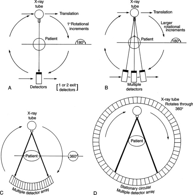
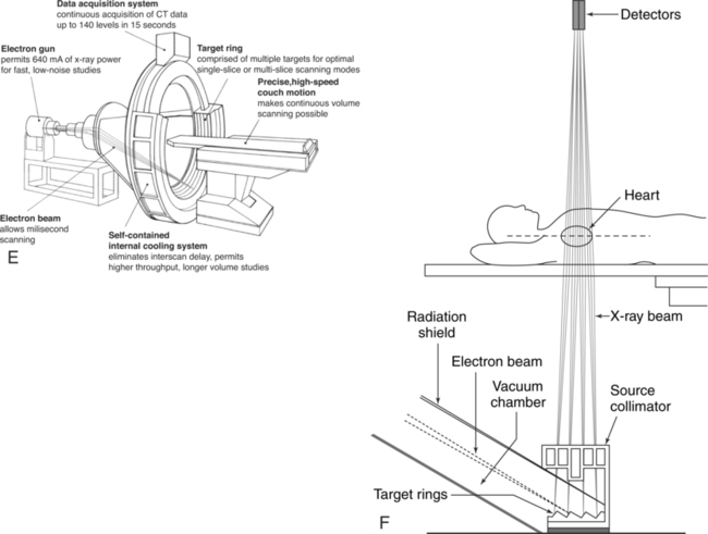
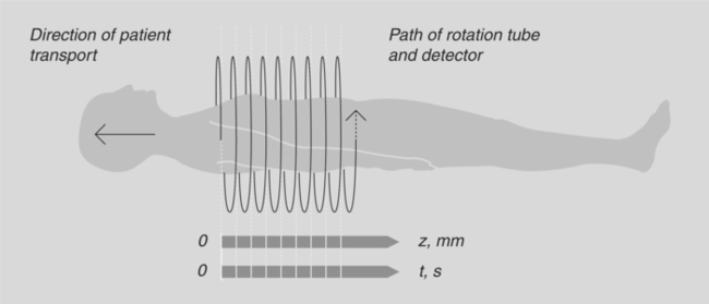
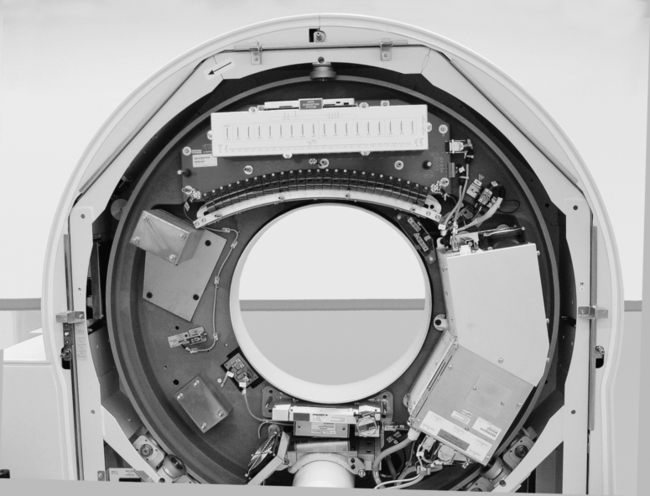
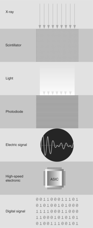
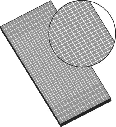
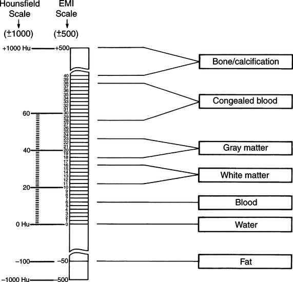
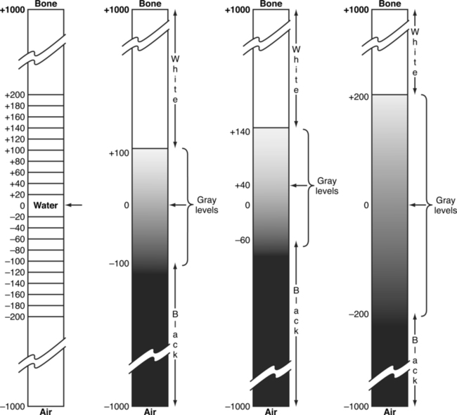
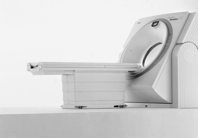
CHAPTER 9 After completing this chapter, the reader will be able to perform the following: Computed tomography (CT) is a specialized modality that links the basic theory of body section radiography with a computer system to produce the anatomic images. The fundamentals of computer technology as it applies to radiography are presented in Chapter 2. The basic principles and terminology are similar for all computer-enhanced techniques, with minor variations applicable for CT and magnetic resonance imaging (MRI). The physical principles of CT are presented, but a detailed discussion is beyond the scope of this book. CT appears to be a very recent innovation, but the theoretic principles were presented by Radon in 1917. This Austrian mathematician proved that it was possible to reconstruct a three-dimensional object from the infinite set of all of its projections. The actual breakthrough in making CT a useful diagnostic tool was made by Hounsfield in 1967. It was not until 1971, however, that the first working model was installed and ready for clinical trials. The transition from Radon’s hypothesis to Hounsfield’s breakthrough was aided by the experimental work of many researchers, including Oldendorf and Cormack. The use of CT has expanded since 1971, and new developments are occurring rapidly. Each major innovation heralds a new generation, or category, of CT scanners. These generations are identified primarily on the basis of the geometry of the mechanical scanning motions. Each successive generation has shown improvement in scanning mode, detection system, and rotational movement (degrees of rotation). The main result of the changes made to each of the successive generations of CT systems has been an increase in scanning speed. Scan times have been reduced from approximately 5 minutes for early slice by slice acquisition units to less than 0.4 s for current fourth-generation volume data acquisition (spiral or helical CT) scanners. The unique design of the electron beam CT (EBCT) systems, sometimes referred to as fifth-generation CT, has made possible scanning times of 50 to 100 ms. Figure 9-1 illustrates the beam geometry for the first four generations of CT scanners and the basic design of an EBCT system. 1. Long examination times due to interscan delay 2. Omission of portions of the anatomy due to inconsistent respirations 3. Inaccurate reformatting of three-dimensional (3D) images due to inconsistent respirations 4. Only a few slices can be scanned during the maximum contrast enhancement phase A change in the fourth-generation beam geometry led to a scanning technique known as volume data acquisition scanning, commonly referred to as spiral, or helical, CT scanning, depending upon the manufacturer of the equipment. In these systems, a continuous x-ray beam is used to produce the scan while the patient is continuously moved (transported) through the gantry. The continuous movement of the tube around a moving patient yields a spiral geometric path that allows for the collection of a large volume of data in a short period (Fig. 9-2). In fact, the scan times have been reduced to less than a second in this type of system. This type of scanning is made possible through the use of the slip ring geometric design in which there is a set of stationary conductive rings that allow the components of the CT system to continuously rotate by means of conductive brushes that serve as sliding contact points for the transmission of electrical current. Figure 9-3 illustrates the components of the spiral CT scanner within the gantry. This design eliminates the need for the electrical cables that restricted the movement of the x-ray tube in the previous generation of CT scanners. In earlier computed tomographic units xenon gas detectors were used. They operated by means of ionization of the xenon gas in response to the x-radiation. The ions collected on parallel plates connected to amplifiers to produce the signal. Today scintillators are primarily used to convert the x-rays to light. A photodiode is incorporated into the system to convert the light produced by the scintillator into an electrical signal that is collected and used to produce the image. Figure 9-4 illustrates the process by which the remnant radiation exiting the patient is converted into a digital signal that is used to produce the image. The detectors used vary with the manufacturer. Siemens has developed what they refer to as an ultrafast ceramic (UFC). This material has a very short afterglow, which improves the resolution of the finished image (Fig. 9-5). Note the chessboard pattern of the plate. The illustration shows 16 rows or lines. Older systems had only one detector line producing only one slice per acquisition. The multislice systems discussed here utilize detectors with multiple lines allowing a wider section of the patient to be imaged in the same acquisition period. Among the advantages of this technology is the reduction in examination time. Higher end systems are capable of imaging the entire body in less than 10 seconds. The advantage to this is that the patients are required to hold their breath for shorter periods. There is also a corresponding decrease in motion artifacts. CT is the production of reconstructed images from information acquired from the remnant radiation through one of the image reconstruction algorithms. These transmitted x-ray photons represent some amount of attenuation within the patient. They are compared with the intensity of the radiation from the x-ray tube, which is measured by a special “reference” detector, to give relative transmission values after digitization. The attenuation values of various tissues are related to the attenuation value of water and may be arranged as a scale (Fig. 9-6). These scale values are called EMI, or Hounsfield, numbers and represent the various CT digital numbers used to reconstruct the image. When the image is produced, the scale (CT digital) numbers represent a certain brightness level. Figure 9-7 illustrates how the scale numbers and brightness level are related. The brightness level (gray scale) can be manipulated to demonstrate different structures in the image. This manipulation, or variation in the relation between the scale numbers and level of brightness, is often called windowing, or setting a window. The window is controlled by the operator of the CT unit and usually set as a window width and window level. The window width represents the range of scale numbers used for the gray scale. Adjusting the window width is equal to adjusting the contrast of the image. The window level represents the midpoint of the gray scale and can be considered a density adjustment. When viewing an image, these values can be adjusted, usually by the radiographer, to enhance certain anatomic structures. The effect of varying window width and window level is illustrated in Figure 9-8. The entire CT suite should follow the same basic design and construction requirements as those for a special procedures suite in regard to radiation protection standards, concealed wiring, emergency equipment, and air conditioning. All equipment should be explosion-proof and should meet the requirements specified by the National Fire Code.1 The imaging group contains all of the elements necessary to produce an image, including the x-ray generator, x-ray tube, and detector system. The generator, x-ray tube(s) and detector(s) are located in housing called a gantry (Fig. 9-9), which also contains the mechanics that provide the motion used in the CT unit. The gantry housing conceals the motion of the x-ray tube and detectors. The equipment will vary depending on the generation of CT equipment. (See Suggested Readings at the end of the chapter for references on the mechanics of the gantry.) Each CT gantry comes with a patient table or couch that is styled according to the individual manufacturer’s specifications. The purpose of the table or couch is to support and move the patient through the central opening in the gantry. Movement of the patient couch can be controlled either by the computer or manually in a horizontal plane. The gantry can be angled with respect to the body axis before the scanning procedure. With the images collected from a series of axial scans, it is possible for the computer to combine segments of the images to create a new image in other planes.
Computed Tomography
 Describe the history of computed tomography
 Identify the basic mechanical computed tomography designs
 Describe the physical principles of computed tomography
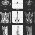
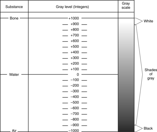
 Identify the types of image display and storage
 Describe computed tomographic room design
 Describe electron beam computed tomography
STANDARD COMPUTED TOMOGRAPHY
Historical Perspective
Mechanical CT Designs
Physical Principles
Data Acquisition
Image Reconstruction
Room Design
Equipment
![]()
Stay updated, free articles. Join our Telegram channel

Full access? Get Clinical Tree


Computed Tomography