Introduction
The process of creating a physical three-dimensional (3D) printed model from medical imaging data is complicated and involves numerous steps. In order for a patient-specific anatomic model to be suitable for 3D printing, segmented anatomical regions of interest must be designed, prepped, and then converted into 3D file types that are recognized by vendor-specific 3D printing slicing software. Common, vendor neutral file formats for printing represent 3D geometry by a triangulated polygon mesh surface with node and vector data and include standard tessellation language or stereolithography (STL), alias wavefront object (OBJ), virtual reality modeling language (VRML), ZPR (a file format created by ZCorp), additive manufacturing (AMF), and 3D manufacturing format (3MF).
The STL file format, invented by the Albert Consulting Group for 3D Systems commercial printers in 1987, has been the predominant file format choice for years. There are two types of STL files: binary STL files that describe a single part and ASCII STL files that contain multiple independent parts. No color or texture is specified in the STL file format. A binary STL can be printed with a single material property, thus is ideal for printing a single component such as an organ, implant, or surgical guide. Multiple binary STL files can be combined or an ASCII STL file can be used to produce multicolored or multimaterial anatomical models such as a kidney and tumor (e.g., two different colors) or an aorta with calcification (e.g., a soft material for the aorta and hard material for the calcification). Since STL files do not encode color or material properties, those are selected using 3D printer-specific software.
In 2011, an initial effort was made to move away from STL files and the AMF was created. However, this file format was never fully adopted by the industry and 3D printer manufacturers. More recently, in 2015, an industrial effort led to the creation of the 3MF file format. This file format reduces the file size and enables the file to carry other data, such as units, color, lattices, and textures. Similar color and texture information is also incorporated in VRML files.
Regardless of the file format, in the preparation phase, minor changes may be necessary to make the model more suitable for printing or major modifications to the model might be needed to facilitate intervention planning. Additionally, model analysis, digital planning, and surgical simulations may be performed in computer-aided design (CAD) software and personalized surgical guides, templates, and molds may be designed. In this chapter, CAD principles and common tools/operations used for medical models will be discussed and clinical examples will be provided. Understanding these tools and methods is critical for any radiologist overseeing the creation of 3D printed models in a hospital setting and can help radiologists to work with surgeons to optimize treatment plans and execute surgeries.
CAD Principles
In medicine, CAD systems allow for the visualization and manipulation of 3D anatomical and associated structures as defined by geometrical parameters. There are many CAD programs where objects can be constructed and editing performed ( Table 4.1 ).
| Program | Company |
|---|---|
| 3-matic and Magics | Materialise (Leuven, Belgium) |
| 3ds Max, Fusion 360, Inventor, Maya, Meshmixer | Autodesk (San Rafael, CA) |
| Blender | Blender Foundation |
| Geomagic Freeform | 3D Systems (Rock Hill, SC) |
| Meshlab | CNR, distributed under the GPL 3.0 Licensing Scheme |
| Rhinoceros | Robert McNeel and Associates (Seattle, WA) |
| Solidworks, CATIA | Dassault Systèmes (Waltham, MA) |
The majority of the CAD software uses solid modeling principles to create 3D representations of objects of interest. Apart from solid modeling, other techniques for the creation of objects include surface modeling (described below), parametric modeling (where a variety of parameters such as dimensions, features, and material properties are input to derive the required geometry), and 3D surface scanning.
Constructive solid geometry (CSG) and boundary representation are the two main methods used in solid modeling. CSG uses Boolean operations (merge, subtract, etc.) to create complex objects from instances of simpler forms such as cylinders, rods, and cubes. Two-dimensional (2D) representations may be swept along a plane or other trajectory to form more complex solid objects and then manipulated against other primitives.
Sweeping operations are also a feature of boundary representation modeling which connects faces, edges, and vertices with geometric surfaces, curves, and points. This technique offers a powerful method to create solid models of unusual shapes. Some well-known boundary representation systems are ROMULUS, Parasolid, and ACIS. The features of these systems form the basis, or are incorporated, into other CAD products.
Solid objects created using 3D modeling techniques can be combined with 3D models rendered from medical imaging, as well as STL files, to form composite images. In addition, 3D and four-dimensional (4D) data visualization, processing, and analysis software can produce additional objects, typically using surface mesh modeling where the surface of the object is represented by a simple surface mesh of vertices and edges. Image segmentation software, introduced in Chapter 3, along with associated modules can be used to create the integrated forms. This software can also post process medical image data using the following mesh modeling techniques. Once a segmented anatomical region of interest has been defined from volumetric medical images, there are two commonly used approaches to model parts by surface mesh modeling, tessellation and the marching cubes algorithm. The most widely used method is the marching cubes algorithm, where the extracted polygonal mesh of an isosurface from 3D voxels is divided into a discrete set of cubes from the input volume associated with that part. This was developed by William Lorensen and Harvey E. Cline as a result of their research at General Electric. The approach uses information from the original 3D imaging slices to derive interslice connectivity, surface locations, and surface gradient information with the resulting triangle model being displayed on conventional graphics display systems using standard rendering algorithms.
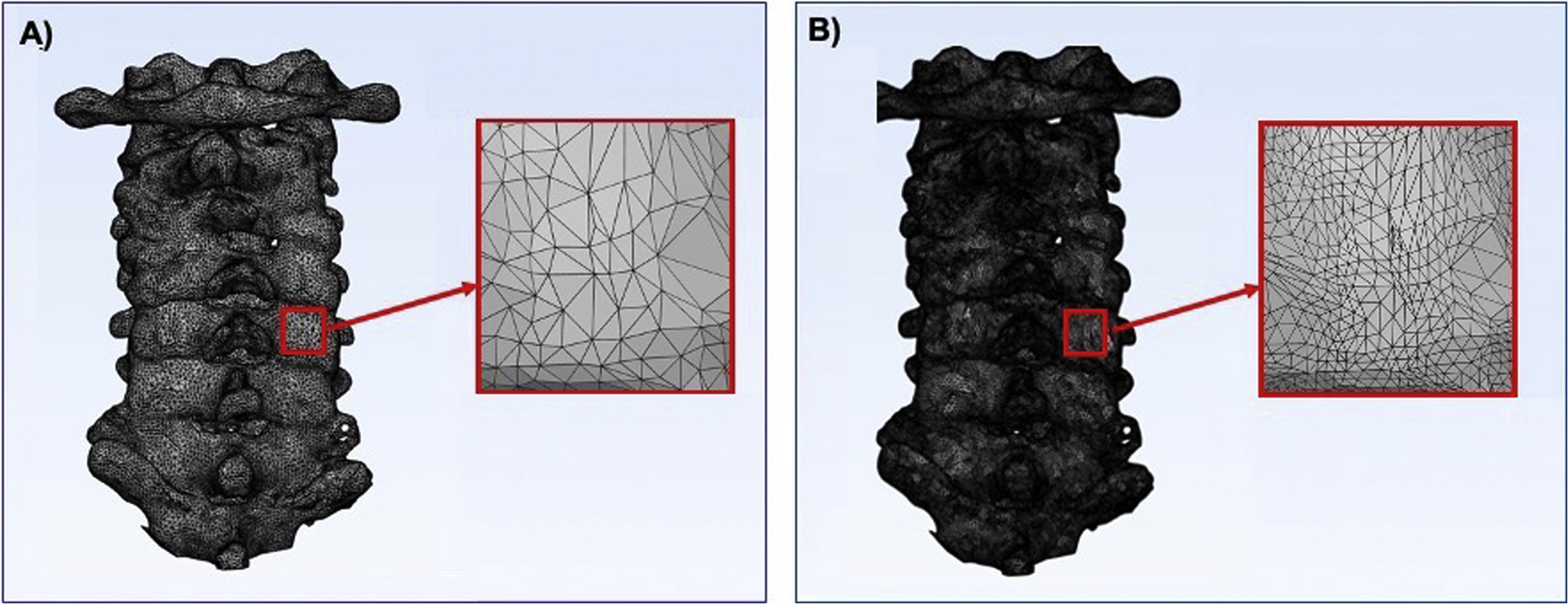
A second approach to CAD modeling is tessellation where the polygonal data are converted into a number of triangles proportional to the total surface area of a specific part in question. A higher number of triangles can more accurately represent the part, whereas a smaller number of triangles would decrease the surface detail, resulting in a less accurate representation of that part ( Fig. 4.1 ). Higher triangle counts need more computer processing power to render and are saved as larger file sizes due to the information stored from each triangle’s vertices; therefore, a balance of surface quality and file size needs to be taken into account when selecting an appropriate number of triangles of a given part. Cut planes, to reduce the size of the model and surface connectivity, can also play a role in reducing the file size while still maintaining a higher level of surface quality. Decimation can be used, as well, to reduce the triangle count of a part. This allows users to select an amount of reduction of triangles in a specific part in order to reduce its size while still maintaining an appropriate number of triangles to represent the part.
Design Operations
Anatomic Models
Once a 3D file has been generated from medical imaging data, further postprocessing of the mesh models may be necessary to ensure that the geometry is suitable for printing. A 3D triangular mesh file consists of three vertices stored in a counterclockwise fashion with a unit normal that defines the outer edge of a triangle. To be suitable for printing, each triangle in the file must be shared with the edge of an adjacent triangle and their surface must be facing the proper direction. Diagnostic testing can be performed to assess errors in triangulation and, in some cases with equipped software, the errors can automatically be repaired.
Some operations may be performed to ensure that the files sent to specific slicing software prior to printing have a decrease in common errors that will potentially make these anatomic models print at a higher success rate. Commonly used design operations include smoothing, wrapping, Boolean operations, labeling, hole filling, mirroring, hollowing, and adding shells. These tasks do not make significant changes to the anatomy but allow the user to refine the final parts for proper printing.
Smoothing, which helps to rectify jagged or unrefined areas, may be performed to reduce the pixelated appearance of a model. It is important to note that higher levels of smoothness can change the part’s volume and dimensions and more smoothing can decrease the ability to differentiate nearby structures ( Fig. 4.2 ).
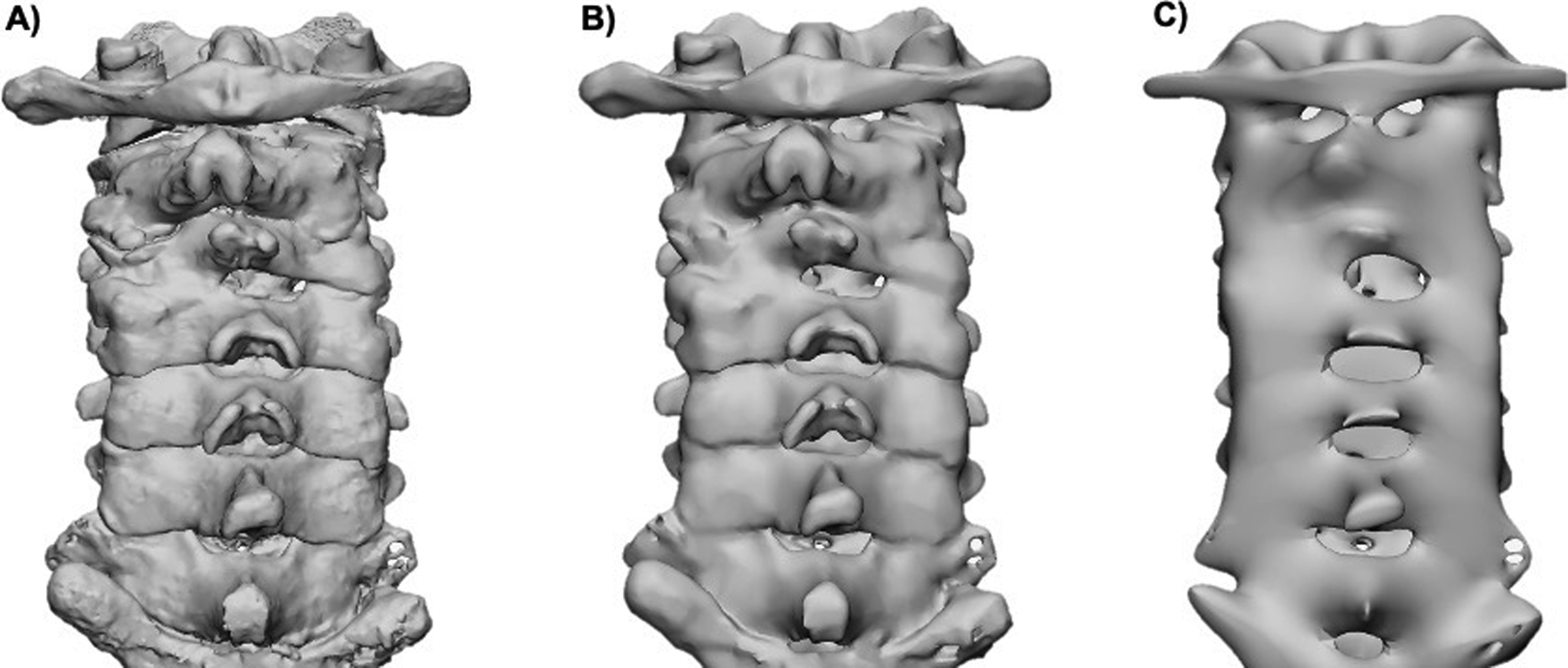
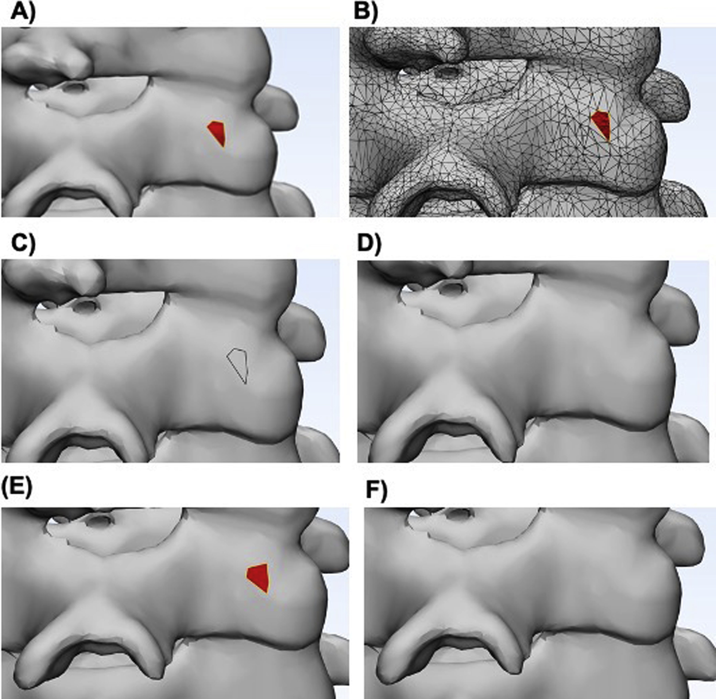
Missing triangles result in holes that are not acceptable for printing since the model will not be “watertight” causing errors due to the gaps in geometry. If there are holes in the mesh, then they must be filled using tools such as hole filling or face extruding to close the gaps. Wrapping operations will create a wrapping surface of the selected entities and can be used to filter small inclusions or close small holes. Wrapping the mesh model generates a watertight STL model around complex tiles, making these files suitable for 3D printing. If a single anatomical model is composed of multiple STL files, then a Boolean subtraction must be performed before printing so that the printer does not try to print two overlapping parts. Note that triangles with an inverted normal direction may look similar to missing triangles ( Fig. 4.3 ). Since both errors will show you similar defects, it is important to identify whether the triangles are inverted or missing prior to choosing a unification method.
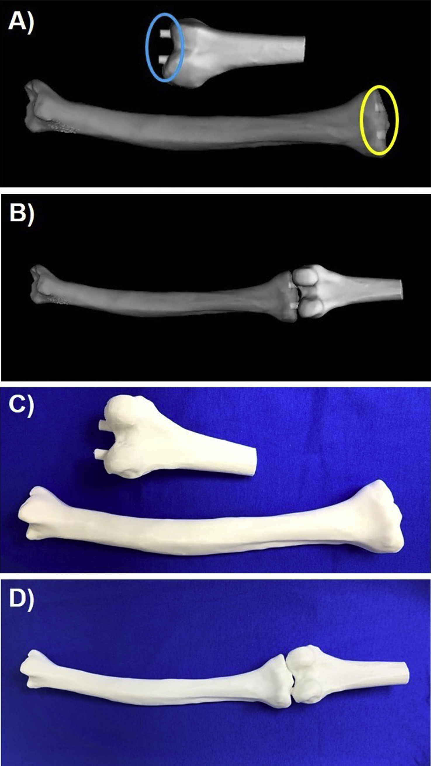
Some anatomic models may be composed of multiple anatomic structures. For example, multiple bones or different heart structures may be delineated in order to demonstrate their relationship to one another. Bones may need to be connected to one another ( Fig. 4.4 ) or the heart may be split and printed in two halves to better show the internal structures (Figs. 6.8 and 6.9). In these cases, support structures such as cylinders, that extrude on one piece and intrude on the other, or slots, where small magnets are placed, can be created to hold the parts together. Note that these additional parts do not change the design of the anatomic structure, but aid in the model’s clinical utility.
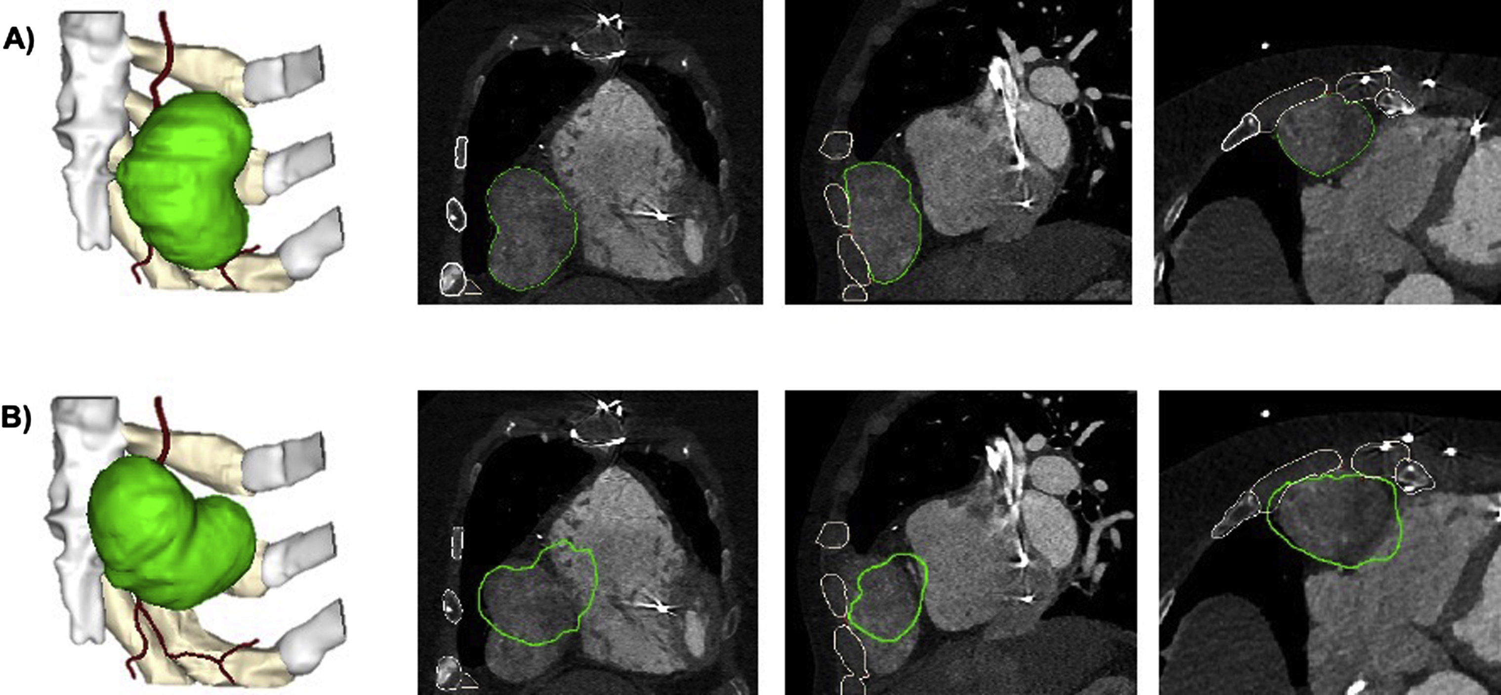
Although these operations are imperative in most cases, some can be misused or overused to the point that the mesh is no longer accurate when compared to the original dataset. Users must educate themselves on these operations and the correct order in which they should be performed so they can associate how these actions influence the mesh file in order to use them safely. If significant postprocessing, such as smoothing, is made to the model, it is important to verify that the model is still an accurate representation of the anatomy of interest. In order to verify this, the contours of the STL file can and should be routinely checked against the source data. In the example below, it is also important to ensure that no translations or rotations of the models are made, so that the data can be accurately registered ( Fig. 4.5 ).
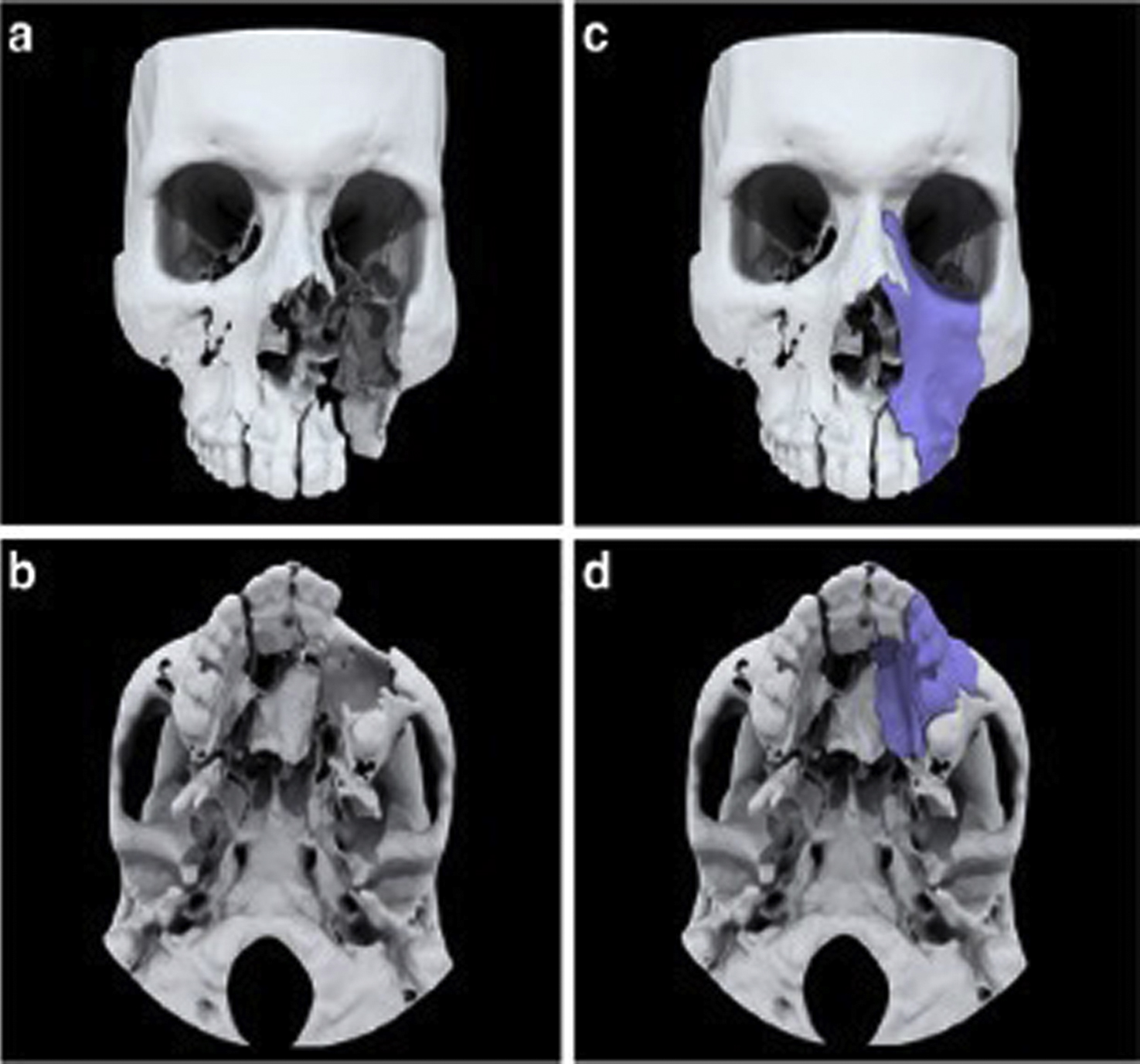
To facilitate intervention planning, major modifications to 3D anatomic models may be necessary. Major modifications significantly alter the anatomy as derived from the medical imaging data and can include mirroring, subtraction of a device/implant, or addition of a graft or implant template ( Fig. 4.6 ).

