Contrast Injectors
Indications
In contrast-enhanced CT and MRI, it is desirable to have a homogeneous intravascular distribution of the contrast medium (CM) for the duration of the contrast study to ensure optimum visualization of the vessels and organs. A power injector is much better for this purpose than manual injection techniques. The use of a power injector also eliminates personnel exposure to scattered radiation since the infusion pumps can be started and stopped from an adjacent room by remote control.
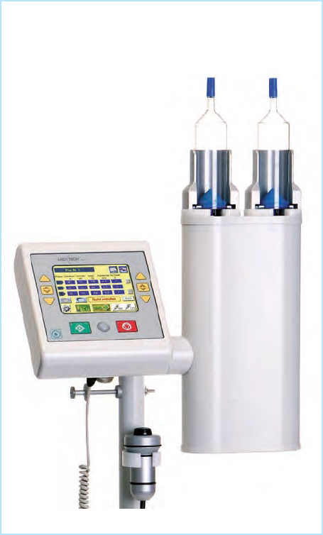
Good results have been obtained with dual-head injector systems ( Fig. 191.1 ). After the contrast bolus has been injected, a dual-head system can flush the injection tubing and the afferent arm veins of the patient with an isotonic saline chaser from a second syringe to reduce the necessary amount of CM. This not only lowers costs but also reduces the potential nephrotoxic effects of some contrast media.
Contraindications
If the patient has a prior history of contrast intolerance, a new contrast injection may be a reasonable option only if the individual risk-to-benefit ratio is carefully assessed and the patient is given IV premedication with H1 and H2 blockers and corticosteroids. It may be necessary to confirm (and document!) that the patient does not have angle-closure- or narrow-angle glaucoma or prostatic hypertrophy (premedication side effects) and that ambulatory patients will refrain from operating a motor vehicle soon after the examination (prolonged reaction time).
Possible Complications
A test injection of isotonic saline is the best way to make certain that the peripheral IV catheter for the contrast injection has been correctly placed within the vessel and can handle the proposed flow rate (see Fig. 196.3 ). Failure to do this could result in a perivascular contrast injection with pain and local pressure-related complications or even necrosis at the injection site.
An initial, moderate intolerance reaction or anaphylactic shock in response to contrast administration may be manifested by sudden sneezing, nausea or vomiting, urticaria, circulatory collapse, or loss of consciousness. This type of reaction requires immediate, specific therapy (see p. 24). Before any kind of infusion is started, all air should be carefully removed from the system to avoid an air embolism.
Material Preparations
Disposable sets are available that contain all necessary supplies (pressure syringes, tubing with adapters, valves, etc.) in a pressure-resistant design ( Fig. 191.2 ).

When unpacking and connecting the lines between the infusion pump and the patient, be sure to practice sterile technique and either wear gloves or use a hand sanitizer ( Fig. 192.1 ). If your hands are wet with alcohol, do not touch the adapters or connectors because contact with alcohol will make them brittle and may cause them to crack ( Fig. 192.2 ). This cannot happen if you let your hands dry briefly after sanitizing them. Next remove the two injection syringes from their package and insert them () with the plunger head down (, weakest part of the system) into their holders in Fig. 192.3 .


Place the injector in a vertical position ( Fig. 192.4 ). Then enter the syringe type that is being used (, Fig. 192.5 ). Generally the filling speed for the contrast syringe should not exceed 3 mL /s (, Fig. 192.6 ). If drawn at a faster speed, the viscous CM could create foam, making it harder to remove the air from the system later on.


Push the button that raises the plunger (shown here in blue) to the “ready to fill” position ( Fig. 192.7 ) and confirm that the patient is not yet connected (precaution against air embolism, Fig. 192.8 ). Use this time to remove the tubing from the set and connect it.


While the plungers are being raised, connect the two lines to the built-in valves (shown here in green, Fig. 193.1 ) by twisting them 180° clockwise (). Do not overtighten the connectors; otherwise they may be very difficult to disconnect later since the CM is somewhat viscous and may acquire a sticky consistency when exposed to air. Connect the tubing for the CM (in this case green-coded) on the left side and the white-coded pressure tubing for the saline on the right side. Figure 193.2 illustrates how the setup should look. The built-in valves permit flow in one direction only: either from the solution bottle toward the syringes () or from the syringes toward the patient ( in Fig. 193.3 ). If the plungers are still moving when the hookups are being made, air flow through the valves may produce a whistling sound; this is a normal occurrence and is no cause for concern.


Now connect the green-coded line to the CM bottle by first removing the protective cap (), inserting the spike ( in Fig. 193.4 ), opening the vent valve ( in Fig. 193.5 ), and squeezing the drip chamber two or three times () to fill it one-third to one-half full ( Fig. 193.6 ). Do the same on the other side with the saline bottle. Then press the button to draw CM into the syringe ( Fig. 193.7 ). Enter the desired fill volume, activate the plunger-down sequence ( Fig. 193.8 ), and repeat these steps on the right side for drawing saline into the second syringe ( Fig. 193.9 ).


Next connect the (straight or coiled) patient line ( Fig. 194.1 ) so that all air can be removed from the system. With the injector in a vertical position, press the yellow button to remove the air from the CM limb before the patient is connected. This triangular button () activates a very slow forward flow that can be stepped up if necessary by pressing the square yellow button () one or more times ( Fig. 194.2 ). Meanwhile hold the end of the line over a collection vessel until all the air has been expelled ( Fig. 194.3 ). Do the same on the right side for the saline limb of the system ( Figs. 194.4, 194.5 ), then hang the sterile end of the tubing on the special holder ( Fig. 194.6 ) without touching it.


Given the importance of avoiding IV air injection (risk of air embolism!), confirm twice on the unit that all air has been expelled from the system ( Figs. 194.7, 194.8 ). Then invert the injector (), tilting it down from the vertical fill position to the injection position ( Fig. 194.9 ). Make sure that the tip of the injector is level with the arm of the supine patient (it should not be higher or lower, if possible).


Before you connect the high-pressure tubing to the IV catheter in the patient’s arm, make sure that the catheter is within the vessel and can tolerate the proposed flow rate. Many radiology departments do this by preparing kidney basins that are stocked with airless high-pressure tubing in addition to a 5- or 10-mL manual syringe filled with sterile isotonic saline ( Fig. 196.1 ). Inject this test bolus briskly () into the IV catheter ( Fig. 196.2 ) and watch closely to see if the saline passes freely through the catheter and into the vein, or if it extravasates and forms a subcutaneous wheal (, Fig. 196.3 ). In the latter case the catheter should be removed () and a new IV access should be established.
Using the test-bolus function of some injection systems may be problematic if the test is done from an adjacent room without having a colleague directly observing the venipuncture site to see if extravasation occurs.


The line connected to the IV catheter may be straight ( Fig. 196.4 , right side), or coiled high-pressure tubing may be used as an alternative ( Fig. 196.4 , left side). The advantage of coiled tubing is that it is more compliant and less likely to become trapped, for example, between the moving CT gantry and the patient table.
Never use “ordinary” extension tubing because it may lack the necessary pressure stability (thinner, softer wall) and may even burst during the injection ( Fig. 196.5 ). If you have ever had to clean up sticky contrast material that has been sprayed all over the scan room by pressure from the infusion pump, you will appreciate the importance of heavy-duty tubing.


Related posts:


Stay updated, free articles. Join our Telegram channel

Full access? Get Clinical Tree


