(1)
IMAGE Center, Southern Illinois University, Carbondale, IL, USA
Abstract
In this chapter, methods are described for preparing biological specimens for examination in the scanning electron microscope. Conventional procedures are described for handling cells grown in liquid culture as well as on substrates such as culture dishes, slide culture chambers, or agar. These protocols may be used to process not only cultured organisms but also larger botanical and zoological specimens.
Key words
Scanning electron microscopyBiological specimen preparationConventional SEM preparatory techniques1 Introduction
In biological studies, the major advantage of the scanning electron microscope (SEM) is to examine the morphology and surface detail of bulk specimens at very high resolution. These specimens may vary from individual cells grown in culture to solid tissues or perhaps entire organisms measuring several centimeters in size. It literally permits an “in-depth” study of such specimens with great topography due to the tremendous depth of field available to the operator. SEM studies typically investigate the external features of a specimen, in contrast to transmission electron microscopy (TEM) studies, where intracellular exploration is the major focus. The SEM can be used to probe internal cellular detail, however, if one removes the overlying material, perhaps by fracturing, cutting, or tearing into the specimen. An understanding of the operational principle of the conventional SEM is useful since the quality of images obtained will be affected by how specimens are prepared for SEM examination.
The SEM is unlike most conventional imaging systems, including light microscopes and TEM, since it does not contain image-forming lenses. The lenses in the SEM do not form images but act as a set of three condenser lenses, in a demagnification series, to focus an extremely small spot, or probe, of electrons on a solid specimen. When the high-energy, accelerated electrons strike the specimen surface, they generate different forms of energy or signals. These signals include secondary electrons, backscattered electrons, X-rays, light, and heat. With the appropriate detector, these signals can be captured, yielding different sorts of information. For example, secondary electrons give information related to topography (the three-dimensional image), backscattered electrons give information primarily about differences in atomic number, X-ray signals reveal the types of elements present, while light and heat may reveal information about the compositional nature of the specimen area being probed.
The electron beam of the SEM is not static but is scanned, or rastered, rapidly over the specimen such that each point that is struck by the electron beam will yield a certain number of secondary electrons, depending primarily on specimen topography. In modern instruments, this information is displayed on a viewing monitor, so the number of secondary electrons from each of the points on the specimen is displayed as pixels having various degrees of brightness and contrast. Points on the specimen that yield many secondary electrons will be displayed as bright pixels, whereas points on the specimen that have fewer secondary electrons will have proportionally darker pixel values.
The quality of the image in the SEM depends on the numbers of electrons collected at each point on the specimen as well as the size of the electron beam that is focused at each point. To obtain higher resolution images taken at higher magnifications, a very small electron beam size is needed. This would be similar to using a larger number of small pixels in a digital image: small beam sizes yield higher resolution. Unfortunately, these small beam spots generate fewer secondary electrons from the specimen, which results in a weak signal. This is manifested as a darker image lacking in contrast and having randomly distributed pixels with varying amounts of brightness. This randomness is termed “noise” and gives a snowy overall appearance to the image. Digital SEMs are able to improve the signal by averaging the signal, effectively reducing the random events while enhancing the true signal events. This results in an image with better contrast, sharp details, and less noise.
The elements that make up the surface of the specimen are the source of the secondary electrons. Elements with a high atomic number yield a high number of secondary electrons and, ultimately, a higher quality image. Unfortunately, biological systems are composed of lighter elements (carbon, hydrogen, oxygen, nitrogen, etc.) and yield a poor signal in the conventional SEM. To overcome this obstacle, biological specimens are processed to preserve structural detail and coated with a thin layer of a high-atomic-numbered element such as gold, palladium, platinum, or osmium.
The steps for preparing biological specimens for viewing in the SEM preparation are very similar to those used to prepare specimens for TEM: fixation in buffered aldehyde, post-fixation in osmium tetroxide, and dehydration in ethanol. Subsequent steps involve transferring the specimens from ethanol to a drying apparatus, mounting the dried specimens on a specimen stub, coating with a heavy metal, and examination in the SEM. Detailed considerations for the choice of buffer and type of fixatives are discussed in Chaptes 1. In this chapter, only the most commonly used reagents and procedures used to prepare specimens for SEM examination are discussed. For greater coverage of these topics, several reference books are recommended [1–3].
2 Materials
1.
Specimen collection supplies (tubes, pipettes, dishes, containers).
2.
Buffers.
A wide variety of buffer systems are available; however, the most commonly used buffer for SEM preparation is the phosphate buffer of Sorenson. Additional buffers as described in Chaptes 1 on specimen preparation for the TEM.
Sorenson’s phosphate buffer consists of two parts: 0.2 M monobasic sodium phosphate, NaH2PO4, and 0.2 M dibasic sodium phosphate, Na2HPO4. The pH is adjusted by mixing the two components as shown in Table 1.2.
3.
Fixatives (see Chaptes 1 on Specimen Preparation for TEM).
The usual fixative regime for SEM specimen preparation consists of 2–2.5 % glutaraldehyde in phosphate buffer followed by post-fixation in 1 % osmium tetroxide, with or without phosphate buffer. Detail on how to prepare these fixatives is given in Chaptes 1. It is especially important that one be aware of the dangers associated with using these chemicals, as discussed in these pages.
4.
Holders or chambers to hold small specimens during processing. The reusable, microporous chambers, sized at 12 × 12 mm, available through various microscopy suppliers (Electron Microscopy Sciences No. 70188, Structure Probe Inc. No. 13215), are particularly useful to safely store very small specimens. Some are available in pore sizes ranging from 30 to 200 μm.
5.
Poly-l-lysine-coated slides (commercial or self-prepared).
Clean several conventional slides with soap and water, rinse in distilled water, and dry the slides in a dust-free environment. Prepare a solution containing 1 mg poly-l-lysine (70,000–150,000 MW) per ml of distilled water. Flood or dip the slides in the poly-l-lysine solution for 10 min at room temperature. Rinse in distilled water, allow to air-dry, and store until needed. Slides coated with poly-l-lysine are available from vendors of electron microscopy supplies.
6.
Microfiltration apparatus consisting of micropore filter, holder, 10 ml syringe.
7.
1 % aqueous carbohydrazide (w/v).
9.
Hexamethyldisilazane (HMDS).
10.
Critical point dryer.
11.
Mounting supplies (sticky tabs, carbon tape, conductive cement, China cement).
12.
SEM specimen stubs.
13.
Sputter coater or vacuum evaporator.
14.
Desiccated or dry compartment to store SEM specimen stubs.
3 Methods
3.1 Preparation of Cell Suspensions (See Note 1)
After cells are grown suspended in liquid culture they must be deposited onto a substrate of some sort. This is accomplished either by allowing the cells to settle and adhere onto the substrate (see Fig. 1) or by trapping them on a microporous filter substrate.
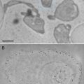
Fig. 1
Candida albicans yeast cells attached to the surface of a poly-l-lysine-coated microscope slide. Specimen was prepared as described in Subheading 3.1.1. Scale bar = 10 μm
3.1.1 Cells Adhered to Poly-l-Lysine-Coated Slides
1.
To adhere cells to a glass substrate, transfer several ml of culture to a microscope slide coated with poly-l-lysine and allow the cells to settle at room temperature for 1 h. If cells do not adhere adequately using the poly-l-lysine procedure, then the organosilane [4] procedure should be used. Protect the slide from evaporation (see Note 2).
2.
Tip the slide to drain the culture liquid, leaving some cells adhering to the surface of the slide.
3.
Use a pipette to very gently flow 2.5 % glutaraldehyde in phosphate buffer over the slide. Take care not to dislodge the attached cells. Allow the slide to stand undisturbed for 1 h at room temperature.
4.
Drain the glutaraldehyde from the slide and rinse three times in phosphate buffer, each for 5 min.
5.
Replace the phosphate buffer with 1 % osmium tetroxide in either phosphate buffer or distilled water. Allow slide to stand for 1 h at room temperature.
6.
Rinse in distilled water, and dehydrate the specimen using a graded ethanol series consisting of 25, 50, 75, and 100 % each for 10 min (see Note 3).
7.
Transfer the slide, still submerged in absolute ethanol, to the critical point drying (CPD) apparatus (see Subheading 3.5.2), and complete the CPD of the specimen.
3.1.2 Cells Deposited on a Microporous Filter
1.
Transfer several ml of culture into the barrel of a 10 ml syringe that contains an attached micropore filtration apparatus (see Note 4).
2.
Place the plunger into the syringe barrel, and apply pressure to the syringe to start the flow of liquid. If the flow stops immediately, too many cells were loaded into the syringe and a higher dilution of cells is needed.
3.
Remove the syringe barrel and associated plunger from the filter apparatus (see Note 5), and dispose of any unneeded cell culture.
4.
Take up several ml of glutaraldehyde fixative into the syringe, place syringe onto the filter apparatus, and press plunger gently to flow fixative onto the cells. Allow to stand at room temperature for 15 min.
5.
Remove syringe from filter, discard unused fixative, and draw buffer into the syringe.
6.
Rinse cells with buffer by attaching syringe to filter and pressing plunger.
7.
Apply 1 % osmium fixative using the syringe delivery method described in steps 5–6.
8.
Discard unused osmium solution, and rinse in distilled water using the syringe.
9.
Dehydrate using a graded ethanol series applied onto the filter through the syringe.
10.
After the cells have been rinsed in absolute ethanol, remove the filter holder and transfer the entire holder, including filter, into the critical point dryer. It is advantageous to replace the screwed-on cover of the filter apparatus with one that has about half of the plastic sawed away using a hacksaw. This leaves an open ring of plastic that is used to hold the filter onto the support.
11.
Critical point dry the membrane, remove from filter apparatus, mount onto a specimen stub using double-stick tab, and coat with heavy metal.
3.2 Preparation of Cells Grown on Substrates
3.2.1 Cultured Cells on the Surface of Petri Dishes
Many cultured cells will grow onto the surfaces of Petri dishes (see Fig. 2a–c), glass microscope slides or cover glasses, plastic flasks, or Permanox slide chambers. Attached cells are processed as follows [5]:
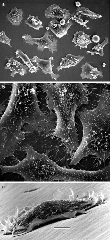
Fig. 2
 Microwave-Assisted Processing and Embedding for Transmission Electron Microscopy
 Electron Microscopy of Microtubule Cytoskeleton Assembly In Vitro
 Visualization of DNA and Protein–DNA Complexes with Atomic Force Microscopy
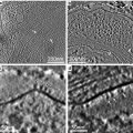 Biological Applications of Phase-Contrast Electron Microscopy
 Correlative Light and Electron Microscopy Using Immunolabeled Sections
 X-Ray Microanalysis in the Scanning Electron Microscope


(a) Monolayer of mammalian cells cultured on the surface of Petri dish. Cells were prepared as described in Subheading 3.3.1 (courtesy of William Kournikakis). Scale bar = 25 μm. (b). Overhead view of mammalian cells cultured on plastic surface. Cells were prepared as in (a) (courtesy of William Kournikakis). Scale bar = 10 μm. (c) Low-angle view of mammalian cell cultured on the surface of Petri dish. Cell was prepared as described in Subheading 3.2.1 (courtesy of Carol Heckman). Scale bar = 5 μm
Related posts:
Microwave-Assisted Processing and Embedding for Transmission Electron Microscopy
Electron Microscopy of Microtubule Cytoskeleton Assembly In Vitro
Visualization of DNA and Protein–DNA Complexes with Atomic Force Microscopy
Biological Applications of Phase-Contrast Electron Microscopy
Correlative Light and Electron Microscopy Using Immunolabeled Sections
Stay updated, free articles. Join our Telegram channel
Full access? Get Clinical Tree
