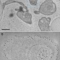
Fig. 1
Scanning electron microscopy (SEM) images of the microchips. The SEM images were recorded at 10 kV (S4700 Hitachi). (a) Image of the backside of a microchip showing the silicon nitride window opening. (b) Image of the front side of the microchip showing the shape of the SU8 spacer, which is 6 μm thick. The silicon nitride window is the dark shape in the middle. Figure reproduced from Ring and de Jonge [8], with the permission of Cambridge University Press
2.
3.
Microspheres: polystyrene microspheres of a 10 μm diameter in aqueous solution (from Structure Probe, Inc., West Chester, PA) (see Note 6). The microspheres have to be washed 3–5 times with HPLC grade water. This is done by adding 900 μL HPLC water to 100 μL of the microsphere stock solution, subsequent centrifugation until a pellet is formed, and resuspension of the pellet with 1 mL HPLC water. This is repeated five times. To adjust the concentration of the microspheres, a 0.2 μL droplet of the washed microsphere solution is placed on a glass microscope slide and examined under a light microscope. The concentration of the microsphere working solution should be adjusted by dilution with HPLC water such that a 0.2 μL droplet contains between 8 and 20 microspheres.
4.
Solution of 0.01 % poly-l lysine in water (sterile-filtered, endotoxin, tested and suitable for cell culture).
6.
Ethanol, HPLC grade.
7.
Pure water, HPLC grade.
8.
Berkshire* Durx* 770 clean room wipers (from Berkshire Co., Great Barrington, MA).
9.
Tweezers with PTFE coating, one with flat, straight tips (Type EMS 2A) (see Note 8) and one with fine and curved tips (Type EMS 7) (from Electron Microscopy Sciences, Hatfield, PA).
10.
Two watch glasses with fire-polished edges, 2½ in. diameter.
11.
1.5 mL microcentrifuge tubes.
12.
Pipetters for volumes ranging between 0.1 and 2.5 μL and between 0.5 and 10 μL.
14.
Gel box with Gel X4 (clear plastic hinged, 50.8 × 50.8 × 6.4 mm, respect. 2″ × 2″ × 1/4″) (from Ted Pella, Inc., Redding, CA).
2.2 Cell Culture
1.
COS7 (African green monkey fibroblast) cells (from American Type Culture Collection (ATCC), Manassas, VA).
2.
Cell culture medium: Dulbecco’s modified Eagle medium (DMEM) (from ATCC) supplemented with 10 % certified fetal bovine serum (FBS), and additional l-glutamine (2 mM) (both from Invitrogen/Life Technologies, Grand Island, NY).
3.
Dulbecco’s phosphate buffered saline (DPBS) modified without calcium chloride or magnesium chloride (from ATCC).
4.
Cell stripper (from Mediatech, Manassas, VA).
5.
DMEM without fetal bovine serum. The serum-free medium will lead to enhanced expression of EGFRs on the cell membrane.
6.
All standard cell culture supplies.
2.3 Labeling
1.
Untreated tissue culture plates, 12, 24, and 96 wells (Corning Inc., Tewksbury MA).
2.
Epidermal growth factor, biotin-XX conjugate (biotin EGF) (from Invitrogen/Life Technologies).
4.
50 mM borate buffer, pH 8.3 (made from 200 mM boric acid/200 mM sodium tetraborate).
5.
Microcentrifuge purification column (Ultracel-100YM, Millipore, Billerica, MA).
6.
Tyrode’s salts with sodium bicarbonate, liquid, sterile-filtered, cell culture tested (Tyrode’s buffer), supplemented with 0.1 % albumin from bovine serum, suitable for cell culture, and 50 mM d-glucose.
7.
Phosphate buffered saline (PBS) (made from 10× concentrate).
8.
4 % glutaraldehyde in PBS (made from 25 % GA, EM grade, from Ted Pella).
9.
100 mM glycine in PBS.
10.
0.2 mL PCR reaction tubes with flat cap.
2.4 Microscopy
1.
35 mm glass bottom dishes, 35 mm diameter (from MatTek Co., Ashland, MA).
2.
Microfluidic tubing of 50 or 100 μm inner diameter (PEEK Upchurch Scientific).
3.
Instrument glass syringe, 1 mL (Model 1001 TLL-SAL SYR, from Hamilton Co., Reno, NV).
4.
10 % PBS in (HPLC grade) water.
5.
Solution of 50 % volume glycerol and 50 % of a solution of 10 % PBS in water.
6.
Pipetter for volumes between 0.5 and 10 μL.
3 Methods (See Note 11)
3.1 Preparation of the Base Microchip for the Microfluidic Chamber
1.
Typically on the same day of usage, the microchips are stripped from their protective resist coating. Use the flat beak tweezers for all subsequent steps. Place (see Note 12) the desired number of microchips (usually 4–10), facing upwards in a clean glass beaker containing 100–200 mL acetone. Move the beaker carefully in a slow pivoting motion such that the liquid achieves a rotational movement around the microchips without flipping them. Continue for at least 2 min. Transfer (see Note 13) the microchips into a similar beaker containing 100–200 mL ethanol. Keep liquid moving in a similar way for another 2 min. Place the microchips onto a clean room wiper for drying (see Note 14).
2.
The silicon nitride surfaces of the microchips are hydrophobic after stripping the resist. For use with biological samples, they have to be made hydrophilic. This can be done by plasma cleaning or glow discharging the microchips for approx. 5 min. A good and cost-effective plasma cleaner is the table top model of Harrick Plasma, Ithaca, NY. It uses ambient air at a low vacuum and a power of 30 W radio frequency.
3.
To promote cell adherence and to keep the microchips hydrophilic for about a day, the base microchip has to be coated with a layer of poly-l-lysine. This coating is applied by immersing (see Note 15) the microchips in a solution of 0.01 % poly-l-lysine (PLL), contained in the wells of a 12-well plate for 5 min at room temperature. We recommend a volume of 1 mL PLL and a maximum of 5–6 microchips per well. Briefly rinse the microchips three times in fresh, 1 mL, volumes of pure water by subsequent transfer of the microchips among wells prefilled with water. Transfer the microchips onto a clean room wiper and let them dry in a dust-free environment (see Note 16). Place the microchips in a gel pack storage box. Alternatively, each microchip can be placed directly into the well of a 96-well plate containing 100 μL of FBS and glutamine supplemented DMEM.
4.
Inspect all microchips (dry or submerged in DMEM) under an optical microscope. Discard any microchips with broken or not entirely clean SiN membranes (see Note 17).
3.2 Preparation of the Spacer Microchip Option #1 for the Microfluidic Chamber
1.
A microfluidic chamber is formed by assembling a base microchips and a spacer microchip with the flat side of the silicon nitride windows facing. A gap between the windows is defined by a spacer layer. Two types of spacing can be used. The first type contains a patterned spacer, as shown in Fig. 2b. This microchip is prepared in the same way as described in Subheading 3.1 but the poly-l-lysine coating (step 3) is omitted.
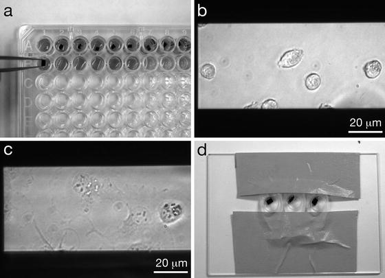

Fig. 2
Seeding cells onto microchips and labeling the cells. (a) Microchips in a 96-well plate, where they will be seeded with cells and the cells will be labeled and fixed. Note the orientation of the tweezers gripping microchips by their sides and not their top surfaces. Tweezers with Teflon coated flat tips are recommended. (b) COS7 cells on windows after ~5 min of incubation. (c) COS7 cells that have adhered to a window, after ~1 h of incubation. (d) Microchips in labeling device are inclined against a drop of labeling solution to reduce the amount of nonspecifically bound label on the sample. Figure reproduced from Ring et al. [11], with the permission of John Wiley & Sons
3.3 Preparation of the Spacer Microchip Option#2 for the Microfluidic Chamber
1.
2.
Briefly vortex the working solution of the polystyrene microspheres. Apply a droplet of 0.2 μL (see Note 19) to each of the four corners of a microchip. Care has to be taken that the droplets are not placed too close to the SiN window. There should be ~8–20 beads in each droplet, depending on the size of microspheres used. When the microfluidic device is assembled and the microchips are pressed together with the pressure needed to obtain a vacuum seal, the gap is typically 5–6 μm for 10 μm-diameter microspheres at the corners (see Note 20). Dry the microchips in a dust-free environment. The number of microspheres deposited on each corner can be checked with reflected light microscopy, also referred to as incident light or epi-illumination. If this type of inspection is not available, we recommend first applying 2–3 0.2 μL droplets of the working solution on a microscope slide and, after the droplets have dried, determine the number of microspheres per drop using conventional light microscope.
3.


Plasma clean or glow discharge the microchips (Subheading 3.1, step 2) (see Note 21). Store the microchips in a gel box.
Stay updated, free articles. Join our Telegram channel

Full access? Get Clinical Tree


