(1)
Center for Cellular Imaging and NanoAnalytics (C-CINA), Biozentrum, University Basel, Basel, Switzerland
(2)
Center for Cellular Imaging and NanoAnalytics (C-CINA), Biozentrum, University of Basel, Basel, Switzerland
Abstract
Electron crystallography is used to study membrane proteins in the form of planar, two-dimensional (2D) crystals, or other crystalline arrays such as tubular crystals. This method has been used to determine the atomic resolution structures of bacteriorhodopsin, tubulin, aquaporins, and several other membrane proteins. In addition, a large number of membrane protein structures were studied at a slightly lower resolution, whereby at least secondary structure motifs could be identified.
In order to conserve the structural details of delicate crystalline arrays, cryo-electron microscopy (cryo-EM) allows imaging and/or electron diffraction of membrane proteins in their close-to-native state within a lipid bilayer membrane.
To achieve ultimate high-resolution structural information of 2D crystals, meticulous sample preparation for electron crystallography is of outmost importance. Beam-induced specimen drift and lack of specimen flatness can severely affect the attainable resolution of images for tilted samples. Sample preparations that sandwich the 2D crystals between symmetrical carbon films reduce the beam-induced specimen drift, and the flatness of the preparations can be optimized by the choice of the grid material and the preparation protocol.
Data collection in the cryo-electron microscope using either the imaging or the electron diffraction mode has to be performed applying low-dose procedures. Spot-scanning further reduces the effects of beam-induced drift. Data collection using automated acquisition schemes, along with improved and user-friendlier data processing software, is increasingly being used and is likely to bring the technique to a wider user base.
Key words
2D membrane protein crystalsBack injectionSandwich methodSpot-scanningCarbon flatnessLow doseCryo-electron microscopy1 Introduction
1.1 History
The foundations of electron crystallography and cryo-electron microscopy (cryo-EM) were laid in the early 1970s. The first structural determination of a biological unstained crystalline specimen was on Bacteriorhodopsin in native purple membranes [1]. This breakthrough required an understanding of the affects of drying on delicate samples, whereby glucose embedding was applied and the limitations from beam damage were overcome using low-dose techniques at the microscope [2]. Taylor and Glaeser [3] used electron diffraction of frozen, hydrated protein crystals and also recorded images of samples preserved in a frozen hydrated state [4]. The cryo-EM technique was further developed by the pioneering work of Dubochet and co-workers at the EMBL, where liquid ethane was used as a cryogen to immobilize specimens in a layer of vitreous ice [5].
Structural biology of membrane proteins is of central importance in cellular biology and for the development of new drugs. Membrane proteins represent the majority of today’s drug targets in pharmaceutical research. Enormous progress has been made in recent years in the structure determination of membrane proteins, whereby the majority of structures were determined by X-ray crystallography. Our databases now contain more than 400 unique folds of membrane proteins (http://blanco.biomol.uci.edu/mpstruc), and this number is growing almost exponentially. A remaining challenge is the understanding of the dynamic function of membrane proteins in the lipid bilayer. Here, electron crystallography can provide significant insight into the conformation of membrane proteins in the membrane-embedded form. Two-dimensional membrane protein crystals are stabilizing the membrane proteins in a lipid bilayer, and the surfaces of the proteins are readily accessible to ligands, changing buffer conditions, or binding partners.
1.2 Electron Crystallography
Electron crystallography studies the structure of membrane proteins in a two-dimensional crystalline arrangement in a phospholipid bilayer membrane. The atomic models of tubulin [6] and of the membrane proteins BR [7], LHCII [8], and water channels [9–13], were among the first protein structures determined by electron crystallography at atomic resolution. Several other membrane proteins classified as transporters, ion pumps, receptors, and membrane-bound enzymes have been studied at slightly lower resolution allowing the localization of secondary structure motifs such as transmembrane helices [14].
Electron crystallography can be used to study membrane protein structures at resolutions of 3 Å or better (e.g., [11, 15, 16]), demonstrating the value of this approach. Electron crystallography represents an alternative method for structure determination, when fragile membrane protein complexes cannot be grown into 3D protein crystals for X-ray diffraction or are not available in sufficient quantities for NMR measurements. Information gleaned from EM reconstructions complement X-ray diffraction data in several ways. EM preparations are often considered more physiologically relevant compared to crystals formed in the presence of detergents, as is sometimes the case with X-ray crystallography. Membrane-inserting proteins that undergo conformational changes between the soluble and the membrane-inserted states are likely to be best studied by electron crystallography. 2D membrane crystals are frequently grown easier than 3D crystals of membrane proteins and offer to the membrane proteins a more native environment than most 3D crystal forms. Membrane crystals are also advantageous for the structure determination of co-crystals, when preformed crystals are to be incubated with protein binding partners. Cryo-EM also offers the possibility to freeze-capture various protein conformational states as freezing rates in ethane ~106 °C/s [17] outperform the transient isomeric states (milliseconds) of proteins [18].
Technological advancements like the availability of coherent intermediate voltage electron sources and nitrogen- or helium-cooled and stable sample stages [19] allow recording of high-resolution data of biological macromolecules. Improvement in detection devices such as CCD and CMOS cameras allows efficient data recording of electron diffraction patterns [20], and the advent of the first direct electron detection devices (DED) is likely to revolutionize also the imaging of 2D crystals. Advancements in sample preparation with the sandwich-back-injection technique using non-wrinkled carbon films [21–23] and the spot-scanning data collection method [24] strongly reduce the resolution-limiting charge effect during data acquisition of tilted samples. Direct electron detectors show promise to also reduce beam-induced and mechanical sample drift when using the so called dose-fractionation or movie mode.
2D membrane protein crystallization usually requires detergent-solubilized and detergent-purified protein typically at a concentration of 1–2 mg/mL. Crystallization can be achieved by various methods [25–30]. So far, the best-ordered 2D membrane protein crystals were obtained after slow and controlled detergent dialysis in the presence of added phospholipids [26]. However, several other 2D crystallization methods were also developed [30–34].
2 Materials
1.
Carbon evaporator (should have an oil-free high vacuum).
2.
Mica sheets.
3.
Petri dishes.
4.
Anti-capillary self-closing tweezers.
5.
Molybdenum TEM grids (e.g., 300 mesh Mo grids from Pacific Grid-Tech, TX [23]), or holey carbon films (Quantifoil, Jena, Germany).
6.
Humid chamber (homemade, constructed from Petri dishes).
7.
Filter paper (Whatman, #1).
8.
Liquid nitrogen in a Styrofoam cup, covered with aluminum foil to reduce boiling, for freezing of the sugar-embedded grids.
9.
For plunge freezing: A plunge freezer, if possible with a closed, humid chamber (e.g., the Vitrobot, see www.fei.com/life-sciences/structural biology/; or a homebuilt device, see Fig. 1).
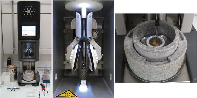
Fig. 1
The plunge-freezing device. FEI Vitrobot fitted with a humidity- and temperature-controlled chamber. The grid is held by tweezers in the center of the device (left). Sample can be added through an opening aperture on either side of the sample chamber (middle). After a predetermined incubation time, blotting is carried out automatically by filter paper blotting pads mounted on pivoting levers at each side of the sample. After a set blotting time (blotting pressure is also adjustable), the sample held by forceps is rapidly plunged into LN2-cooled ethane liquid or slush. The liquid ethane/nitrogen container is mounted directly below the specimen chamber during plunging and moves down for transfer of the grid to a suitable grid box (right). The sample must be kept in cold nitrogen, below the devitrification temperature ≈−150 °C, throughout the process and during transfer to a grid storage box. The frozen sample can then be stored under LN2 until ready for viewing in the TEM
10.
For the sandwich method: 4 mm diameter platinum wire loop (available, e.g., from Ted Pella, Inc., Redding, CA).
3 Methods
3.1 Preparing 2D Crystals of Membrane Proteins for Cryo-EM Analysis
This chapter describes the techniques and methods required for the structural analysis of 2D crystals by cryo-EM. Much effort must be invested to obtain large, single-layered, well-ordered crystals that are the starting point for our investigations. The expression, purification, and crystallization of quality crystals are not covered in the context of this chapter but can be researched in other excellent reviews or books based on these specific themes [14, 30].
Grid sample preparation is equally as important as the operation of the electron microscope for the recording of high-resolution data of 2D crystal samples. The 2D crystalline arrangement of the sample allows efficient extraction of the structure’s signal from extremely noisy images by computer processing. For the choice of the sample preparation, preference is therefore given to methods that perfectly preserve the high-resolution order of the 2D crystals, while the contrast characteristics of the preparation are of secondary importance.
Cryo-EM grids of 2D crystal samples can be prepared using holey or continuous carbon film support grids. However, holey carbon film-coated grids, upon rapid plunge freezing, embed the samples in a thin (~100 nm) layer of vitrified ice. This in most cases provides inferior electrical conductivity, physical stability, and sample flatness compared to a continuous carbon film support [35]. Grids for cryo-EM imaging of 2D crystals therefore usually employ continuous carbon film support. The following protocol describes the preparation of such grids.
3.2 Specimen Preparation
3.2.1 Plunge Freezing
2D crystals can be adsorbed to glow-discharged, carbon-coated grids, blotted and plunge frozen (vitrified) in ethane slush, cooled by liquid nitrogen (see Fig. 1), similar to the preparation of cryo-EM grids with the holey carbon film method.
2.
If the carbon layer is difficult to remove from the mica surface, place mica with evaporated carbon into a humid chamber overnight, to increase ease in floating the carbon off the mica.
3.
Float carbon off the mica onto the surface of a buffer solution. This piece of carbon should be slightly larger than a TEM grid by trimming the mica to size with sharp scissors.
5.
Invert the tweezers with the grid upside down.
6.
Remove a portion of the liquid on the grid with a pipette.
8.
Place the tweezers into a plunger (guillotine).
10.
Transfer the grid into a cryo-holder or microscope cartridge and image with minimal-dose (low dose) cryo-EM techniques.
3.2.2 Sugar Embedding (Back Injection)
Drying of membrane protein crystals in the presence of sugars such as tannic acid [8], trehalose [6, 9, 36], or glucose [15] can preserve the intact ultrastructure of the proteins while eliminating the need for quick-freezing.
2.
Place mica with evaporated carbon into humid chamber overnight, to ease floating the carbon off the mica, although in some cases this might not be necessary.
3.
Float carbon off the mica onto the surface of a buffer solution.
5.
Place the grid with the carbon film facing up onto three drops of sugar solution (see Fig. 2b and also Notes 6 and 7).
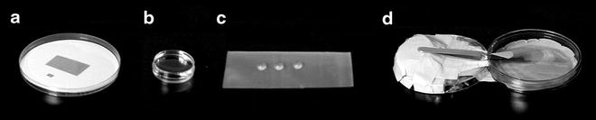
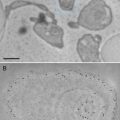
Fig. 2
Sugar embedding of 2D crystals requires a piece of carbon the size of a grid. This can be cut from mica with evaporated carbon (a). The carbon is floated onto a water surface (b) and placed onto three drops of sugar containing buffer solution (c). After adding the crystal solution, the grid is allowed to rest for a few minutes in a humid atmosphere that can be created using Petri dishes (d). The edge of the cover of the right Petri dish was broken off over a stretch of 2 cm, forming a hole where the tip of the tweezers can enter. The bottom of the right Petri dish is covered with a wet filter paper, which increases air humidity when the Petri dish is closed
6.
Turn the tweezers with the grid upside down. The carbon film is now on the lower side of a hanging drop of sugar under the grid.
7.
Remove a portion of the liquid on the grid with a pipette (from the top through the grid bars) to level the solution surface on the grid.
9.
Place grid in tweezers for 60 s into a humid chamber, which can be constructed from three plastic Petri dishes (see Fig. 2d).
10.
With a pipette, remove excess solution from the grid, leaving only about 1 μL across the grid surface.
11.
Turn the tweezers again upside down, and place the grid flat onto two layers of filter paper with the carbon film facing up (draining from the rear).
12.
After sufficient blotting time (e.g., 20 s; Note that blotting time can strongly affect the quality of the frozen crystals) and subsequent freezing in liquid nitrogen, observe the grid in the TEM (see Note 7).
3.2.3 The Sandwich Method
The sandwich sample preparation method embeds the 2D crystals between two layers of carbon film. This preparation offers conductive surfaces one on each side of the sample, which may help reduce specimen charging. At the same time, this protocol presents a symmetrical sample structure to the electron beam, so that physical expansion during electron irradiation will exert a symmetric lateral pressure, so that unidirectional stress and movement are minimised. It may thereby increase the image stability under the electron beam [37]. Another advantage of this method arises when it is used in conjunction with a staining solution, since it can provide a more even staining of the two sample surfaces, even though the second carbon film adds noise to the image (e.g., [38]). The carbon sandwich can be made by placing both carbon films on the same surface of the TEM grid, resulting in the order grid → carbon → sample → carbon [38, 39]. Alternatively, the two carbon films can cover both sides of the TEM grid, as described in [22], resulting in the order carbon → grid/sample → carbon. The latter is presented here:
10.
Lift the carbon film up with a 4 mm diameter platinum wire loop and place it onto the grid from the top side, so that the grid and 2D crystals are sandwiched between the two carbon films (see Fig. 3).
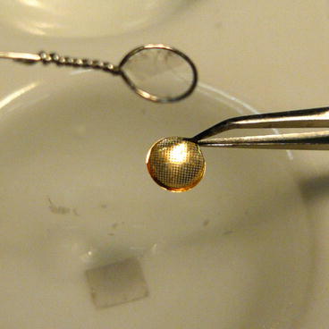
Fig. 3
Transfer of the second carbon film onto the grid to form the carbon film sandwich. The grid holds a carbon film at its lower side, onto which the 2D crystal sample has been adsorbed. The platinum loop is used to transfer a second carbon film onto the grid from the top, forming a carbon sandwich that surrounds the 2D crystals
11.
Blot the sandwich construction from the edge of the grid, using a piece of torn filter paper.
12.
Plunge the grid into liquid nitrogen manually by hand or with a plunge-freezing device and then transfer into the cryo-EM.
3.3 Electron Microscope Operation
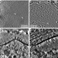
Data collection on 2D crystals with the transmission electron microscope can be performed by recording either images, or electron diffraction patterns, or both. While the Fourier transformations of the images contain amplitudes and phases of the sample structure, electron diffraction patterns allow a more reliable determination of the amplitudes, but lack the phase information.
3.3.1 Recording of Images
Image processing of images of 2D crystals with the crystallographic crystal unbending approach (described below) benefits from large image files of large 2D crystal areas. 2D crystal images were therefore usually recorded on photographic film, which was then digitized with a high-resolution scanner. So far, no CCD camera has produced high-resolution structures of membrane proteins. A new generation of scintillator-covered CMOS camera (e.g., as available from TVIPS, (http://www.tvips.com/) can now record images of 8,192 × 8,192 pixels at good detector quantum efficiency, and the new generation of direct electron detectors as available from FEI (http://www.fei.com/life-sciences/structural-biology/), Gatan (http://www.gatan.com/products/digital_imaging/products/K2/index.php), or Direct Electron (http://www.directelectron.com/) also promises outstanding performances.
The demands of high-resolution imaging dictate that the electron microscope is well aligned with respect to gun and column alignments. These advanced alignments should be carried out by a highly trained engineer or qualified user. After eucentric specimen height adjustment, direct alignments should be applied prior to a dataset acquisition. Common alignments may include aperture centering, pivot point correction, beam rotation and beam centering, along with coma-free alignment for optimal imaging conditions [40].
Recording of images from 2D crystals requires operation of the electron microscope under low-dose conditions, in which the microscope offers the so-called “search,” “focus,” and “exposure” positions. Choose a smaller second condenser aperture and a larger objective aperture (~100 μm or larger). The latter may reduce specimen charging, due to a certain backscattering of electrons onto the specimen. Align the TEM in the “exposure” position, then set up the “focus” position, and finally the “search” position. Cycle through the modes exclusively in the order “search” → “focus” → “exposure,” to prevent hysteresis effects that may degrade the alignment.
1.
 Microwave-Assisted Processing and Embedding for Transmission Electron Microscopy
 Electron Microscopy of Microtubule Cytoskeleton Assembly In Vitro
 Visualization of DNA and Protein–DNA Complexes with Atomic Force Microscopy
 Biological Applications of Phase-Contrast Electron Microscopy
 Correlative Light and Electron Microscopy Using Immunolabeled Sections
 X-Ray Microanalysis in the Scanning Electron Microscope


Search position: The “search” position should allow easy localization of 2D crystal targets, which has to be done at very low illumination intensity. This can on some instruments best be achieved by observing the so-called shadow images, by setting the instrument up in an overfocused electron diffraction mode. Use an electron diffraction camera length of 1 m or longer. Set the second condenser lens to strong overfocus, to spread the illumination over a large sample area. Set the intermediate lens to overfocus, to create a strongly contrasted “shadow image” of the sample. Use a combination of image shift and beam tilt to align the center of the “search” position with the “exposure position.”
Related posts:
Microwave-Assisted Processing and Embedding for Transmission Electron Microscopy
Electron Microscopy of Microtubule Cytoskeleton Assembly In Vitro
Visualization of DNA and Protein–DNA Complexes with Atomic Force Microscopy
Biological Applications of Phase-Contrast Electron Microscopy
Correlative Light and Electron Microscopy Using Immunolabeled Sections
Stay updated, free articles. Join our Telegram channel
Full access? Get Clinical Tree
