, Hong-Mei Han2 and Jan Huebinger2
(1)
Institute for Anatomy and Cell Biology Germany, University of Heidelberg, Heidelberg, Germany
(2)
Department of Systemic Cell Biology, Max-Planck-Institute of Molecular Physiology, Dortmund, Germany
Abstract
High-pressure freeze fixation is the method of choice to arrest instantly all dynamic and physiological processes inside cells, tissues, and small organisms. Embedded in vitreous ice, such samples can be further processed by freeze substitution or directly analyzed in their fully hydrated state by cryo-electron microscopy of vitreous sections (CEMOVIS) to explore cellular ultrastructure as close as possible to the native state. Here, we describe the procedure of self-pressurized rapid freezing as fast, easy-to-use, and low-cost freeze fixation method, avoiding the usage of a high-pressure freezing (HPF) apparatus. Cells or small organisms are placed in capillary metal tubes, which are tightly closed and plunged directly into liquid ethane cooled by liquid nitrogen. In parts of the tube, crystalline ice is formed and builds up pressure sufficient for the liquid-glass transition of the remaining specimen. The quality of samples is equivalent to preparations by conventional HPF apparatus, allowing for high-resolution cryo-EM applications or for freeze substitution and plastic embedding.
Key words
High-pressure freezing (HPF)Self-pressurized rapid freezing (SPRF)Cryo-electron microscopy of vitreous sections (CEMOVIS)Freeze substitution1 Introduction
The quality and the speed of sample fixation is still a major challenge for electron microscopy preparation of biological specimens. Compared to chemical fixation, cryo-fixation is regarded as superior, since all biochemical, physiological, and dynamic processes are instantly arrested in their actual state by a massive temperature drop. To avoid any segregation of molecules by ice crystal growth, a cooling velocity up to 100.000 K/s is intended, resulting in a sample completely embedded in vitreous—or sometimes called amorphous ice [1]. Thin samples like purified proteins on a grid or very small cells can be vitrified by simple plunge freezing [2]. Reaching a proper vitrification of samples in the size of eukaryotic cells and tissues, the use of high-pressure freezing (HPF)—as introduced by Riehle and Moor [3]—is mandatory and nowadays performed through commercially available HPF machines.
Recently, self-pressurized rapid freezing (SPRF) has been established as novel and low-cost cryo-fixation method to freeze biological samples in clamp-sealed copper tubes. Instead of applying about 2,000 bar pressure and synchronous cooling in a HPF apparatus, the tubes were plunged directly into the cryogen. This relatively simple procedure—as compared to the usage of HPF machines—provided excellent results for freeze-substituted and plastic embedded specimens [4]. The authors hypothesized that high cooling speed by plunge freezing in conjunction with simultaneous formation of internal pressure by hexagonal ice and/or super-cooled water expansion (Le Chatelier and Braun principle) supports the vitrification of the sample, at least in parts of the tube. Others provided theoretical calculations on the cooling speed in these capillary tubes with the surprising result, that minimizing the amount of cryoprotectant would improve the preservation of cellular ultrastructure [5]. As pointed out in a subsequent comment to this particular reports, the heat transfer at the tubes outer surface, which is the key limiting factor during sample cooling, was neglected, proving these computations unrealistic [6]. Unfortunately, the thermo-conductive peculiarity and small geometry of the tubes prevent all attempts to install sensors for recording the internal pressure and temperature progression during fast cooling. Therefore, the time line and amount of pressure reached during freezing remains speculative. However, the fact that thinner tube walls are severely deformed during freezing shows that the atmospheric pressure inside tubes is far exceeded (unpublished results). In the same direction points the observations that open tubes always lead to sample damage by ice crystal formation [4].
Hence, the direct way to determine freezing quality is the diffraction analysis of frozen SPRF samples below devitrification temperatures, which was explored in follow-up studies. Typical diffraction patterns of vitrified ice were detected by X-ray diffraction of 10–30 μm areas, unfeasible to differentiate between cells and medium [7]. By cryo-electron microscopy and electron diffraction of much smaller areas in vitreous sections, it was determined that appropriate freezing conditions result in vitrified ice present in intracellular as well as in extracellular areas, as illustrated in Fig. 1. See also ref. 8.
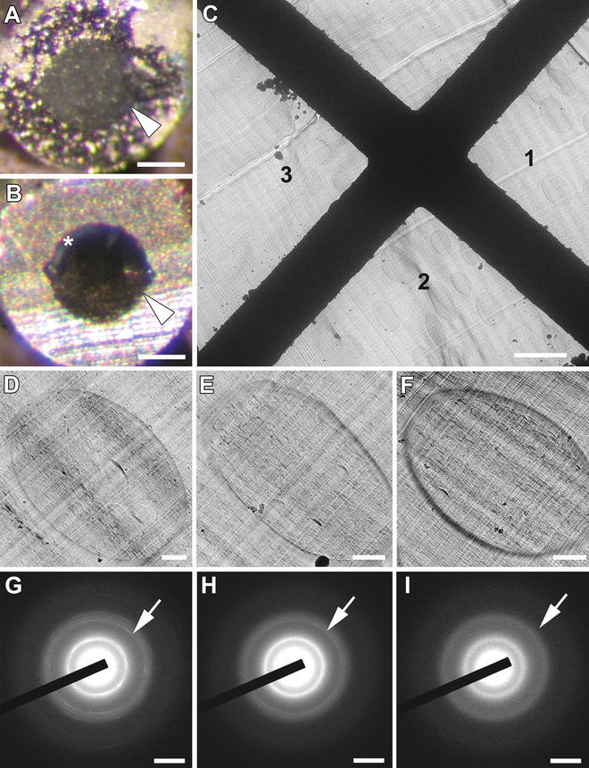

Fig. 1
Determination of vitrified ice in SPRF preparations containing yeast cells. (a and b) Typical stereo-microscopic views of trimmed SPRF aluminum tubes containing cells at −150 °C are shown. Arrowheads point to the border between tube wall and frozen sample. (a) Cells suspended in pure PBS give rise to a “milky” presence of crystalline ice without signs of vitrification. (b) The addition of cryoprotectant results in transparent areas of potentially vitrified regions appearing dark. Note some crystalline regions near the tube wall (asterisk). (c–i) CEMOVIS of a sample cut from a tube-like in (b). (c) Low magnification view with marked regions (1–3). (d) Yeast cell of region 1 shows poor morphologic quality and the appearance of hexagonal ice (d) crystals as dark spots. (e) Yeast cell of region 2 seems without crystals at low magnification. (f) Yeast cell resembling region 3 shows superior morphologic quality. (g–i) Electron diffractograms of regions 1–3 in (c), respectively. Arrows point to the corresponding reflection rings. (g) Diffractogram of region 1 displays hatched circular pattern representing size and orientation of ice crystals. (h) Diffractogram of region 2 displays two sharp rings representative of crystalline ice contamination. (i) Diffractogram of region 3 displays two diffuse rings as typical pattern of vitreous ice, verifying the presence of amorphous ice in SPRF preparations. Scale bars: (a) and (b) = 150 μm; (c) = 6 μm; (d–f) = 500 nm; (g) and (i) = 1/0.4 nm. Modified from Han et al. [8], with the permission of Elsevier
Thus, the general capacity to produce vitreous samples qualifies SPRF as cryo-fixation method for electron microscopy protocols associated with freeze substitution or for direct cryo-imaging procedures like CEMOVIS. Highlighting all facets of sample preparation using freeze substitution would be beyond the scope of this chapter. Therefore, we refer to available protocols [9] and excellent reviews [10, 11]. Figures 2 and 3 give typical examples from prokaryotic bacteria (Escherichia coli), eukaryotic yeast cells (Saccharomyces cerevisiae) to whole organisms like nematodes (Caenorhabditis elegans)—all cryo-fixed by SPRF and further processed by freeze substitution. CEMOVIS was introduced in the 1980s at EMBL Heidelberg [12, 13], gradually developed to a stage, where it can be applied to various biological specimens [14, 15], and provided unprecedented views of different structures in their native cellular environment, such as microtubules [16], desmosomes [17], mitochondria [18], neuronal synapses [19], or pleomorphic membrane structures like mammalian Golgi apparatus [20]. Ultrastructural details of yeast (S. cerevisiae), bacteria (E. coli), and cultured mammalian (COS-7) and human cells (HeLa)—all fixed by SPRF and analyzed by CEMOVIS—are shown in Figs. 2c and 4. After some adjustments, SPRF frozen samples could potentially be used for other cryo-imaging methods like soft X-ray cryo-tomography [21] or for cryo-FIB (focussed ion beam) milling [22].
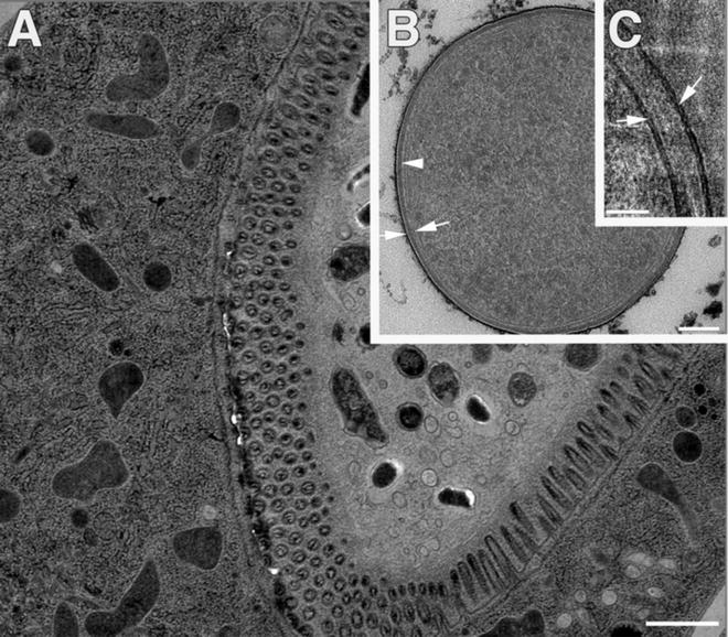
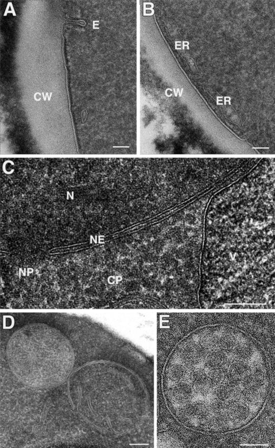
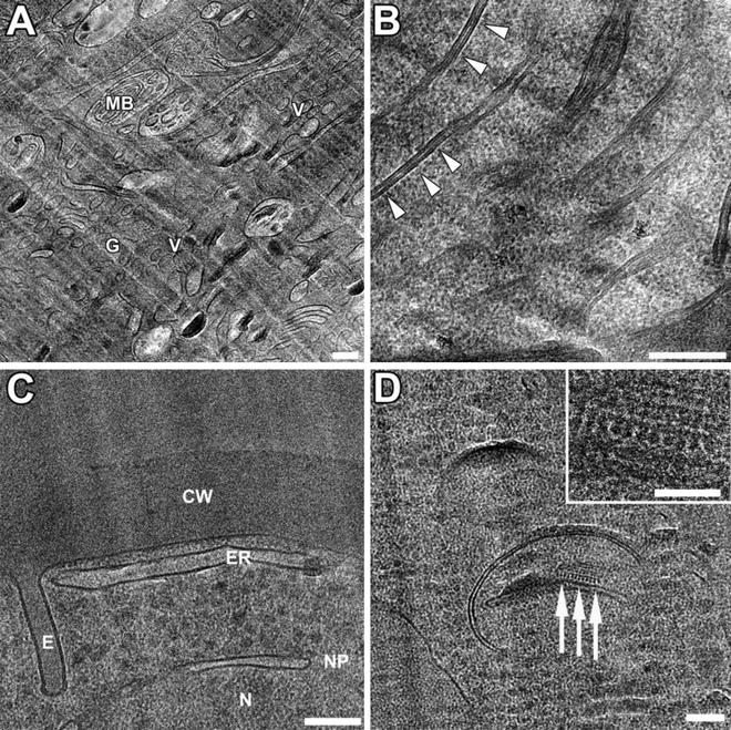

Fig. 2
SPRF preparation of microorganisms (E. coli) and whole animals (C. elegans). (a) Intestine region of a nematode, cryo-fixed by SPRF and subjected to freeze substitution. (b and c) E. coli bacteria fixed by SPRF. (b) After freeze substitution and plastic embedding, the overall morphology is excellent. The bilayers of inner and outer membranes (arrows) and peptidoglycan layer (arrowhead) are clearly visible. (c) CEMOVIS allows for higher resolution of membrane bilayers (arrows). Scale bars: (a) = 1 μm, (b) = 100 nm; (c) = 50 nm. Panels (b) and (c) reproduced from Han et al. [8], with the permission from Elsevier

Fig. 3
Yeast cells (S. cerevisiae) prepared by SPRF and freeze substitution. (a and b) The outer region of yeast cells. Note the cell wall (CW) and the elongated appearance of endocytotic plasma membrane invagination (E) in (a). (b) Cortical endoplasmic reticulum (ER) locates typically close to the plasma membrane. (c) Central area of a cell with cytoplasm (CP), part of a vacuole (V), and nucleus (N). The nuclear envelope (NE) contains a nuclear pore (NP). Higher magnification views of mitochondrium (d), probably during division or fusion, and a multi-vesicular body (e). Scale bars: (a–c) = 100 nm, (d) and (e) = 50 nm

Fig. 4
Higher magnification views of cellular ultrastructure prepared by SPRF and CEMOVIS. (a and b) Cryo-EM of human cells. (a) The cytoplasm of HeLa cells contains Golgi stacks (G), peri-Golgi vesicles (V) and multi-vesicular bodies (MB). (b) Higher magnification of Cos-7 cell mitochondrium. Note the fine details of lipid bilayers in cross-sectioned mitochondrial cristae membranes (arrow heads). The extreme narrow intermembrane space (below 2 nm) indicates a highly energized level of mitochondria during SPRF fixation, representing a “close-to-native” state of the cell. (c and d) CEMOVIS of yeast cells. Morphologic quality is superior in cryo-sections compared to freeze substituted samples (see Fig. 3), where the cell wall seems shrunken during the dehydration procedure. Note also the straight membrane appearances in cryo samples. (c) Shows yeast cell periphery containing cell wall (CW) and nucleus (N). The nuclear envelope includes a nuclear pore (NP). Note the elongated appearance of endocytotic plasma membrane invaginations (E). (d) Fine detail of yeast mitochondrium. The higher magnification (inset) shows membrane-associated regular structures probably resembling ATP synthase particles (arrows). Scale bars: (a–d) = 100 nm, inset = 50 nm. Panels (a–c) reproduced from Han et al. [8], with the permission of Elsevier
The main drawbacks of HPF are determined by the relatively small volume, which can be vitrified thoroughly. Here, SPRF samples in tubes are slightly more delicate to handle than samples for HPF apparatus, especially regarding correlative light and electron microscopy down to the cellular or molecular level—a problem, which is not solved yet for SPRF fixation. Severe deformations of cells can occur in parts of the tube due to growth of large ice crystals (see Fig. 5). But such areas are easily recognized and analysis can be continued elsewhere in the sample.
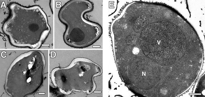

Fig. 5
Artificially deformed yeast cells (S. cerevisiae) as prepared by SPRF and freeze substitution. (a–d) Hexagonal ice crystal growth leads to severe deformations of complete cells. Note that internal ultrastructure is affected as well. Such easily to identify deformations can be found in cells close to the tube wall (see asterisk in Fig. 1b). (e) Non-deformed cells might still have artificial ultrastructure. Note the nucleus (N) and severe segregations in the vacuole (V), most likely induced by growth of small ice crystals during preparation. Scale bars = 500 nm
However, SPRF gives besides its extreme independence and reliability the complete experimental freedom in choosing cryogens and freezing conditions, which are more or less preassigned in HPF machines. Furthermore, due to the completely closed sample volume architecture, SPRF is predestined for infectious and/or biological safety applications, where the sample content or the environment has to be protected from each other. Compared to commercial HPF machines, SPRF is faster in preparation time, is much cheaper, consumes less liquid nitrogen, and is maintenance-free. The last but not the least, SPRF provides by its simplicity the option to perform cryo-fixation of samples out in the field or at expeditions to extreme habitats and environments, as the basic procedure can be operated without electricity.
2 Materials
2.1 Self-Pressurized Rapid Freezing
1.
Cell lines: mammalian cell lines, e.g., HeLa (ATCC No. CCL-185), Cos-7 (ATCC No. CRL-1651), or MDCK (ATCC No. CCL-34); bacteria (e.g., E. coli); yeast (e.g., S. cerevisiae).
2.
Growth medium for your cells.
3.
Phosphate buffered saline (PBS): 140 mM NaCl, 2.7 mM KCl, 8.1 mM Na2HPO4, and 1.5 mM KH2PO4; pH 7.2–7.4.
4.
Cryoprotectant medium: 30 % (w/v) dextran (40 kDa, Sigma-Aldrich Chemie GmbH, Munich, Germany) in PBS.
5.
Centrifuge (e.g., Centrifuge 5810R, Eppendorf, Hamburg, Germany).
6.
SPRF-tubes: copper (outer diameter 0.5 mm/inner diameter 0.22 mm), aluminum (0.6 mm/0.3 mm) (Goodfellow GmbH, Bad Nauheim, Germany).
7.
Adjustable micropipettes (1–1,000 μL).
8.
Micropipette tips: 0.1–10 μL (Eppendorf, Hamburg, Germany); additional pipette tips covering the range from 10 to 1,000 μL.
9.
Fume hood.
10.
Pliers with flat jaws.
11.
Tweezers.
12.
Hair dryer.
13.
Liquid nitrogen (LN2).
14.
Liquid nitrogen Dewar vacuum flasks and Styrofoam boxes.
15.
Compressed ethane gas cylinder with pressure regulator (Westfalen AG, Muenster, Germany).
16.
Plunge freezer (commercial types or homemade).
2.2 Freeze-Substitution
1.
Automated freeze-substitution unit AFS 2 (Leica Microsystems, Vienna, Austria).
2.
Fume hood.
3.
Tweezers.
4.
Leica HPF Cryo-tools (Leica Microsystems, Vienna, Austria) or ordinary scissors.
5.
Liquid nitrogen (LN2).
6.
Liquid nitrogen Dewar vacuum flasks and Styrofoam boxes.
7.
Reaction tubes: 2 and 0.5 mL (Eppendorf, Hamburg, Germany).
8.
Heating block for reaction tubes (needs to be adjustable to 37 °C).
9.
Table-top centrifuge.
10.
Acetone (Science Services GmbH, Munich, Germany).
11.
4 % Osmium tetroxide in water (Science Services GmbH, Munich, Germany).
12.
Uranyl acetate (Polysciences Europe GmbH, Eppelheim, Germany).
13.
Adjustable micropipette and tips (100–1,000 μL).
14.
Deionized water.
15.
Embedding resin: Epon (Serva Electrophoresis GmbH, Heidelberg, Germany).
16.
Oven (needs to be adjustable to 60 °C).
17.
Ultramicrotome (e.g., Reichert Ultracut S, or similar).
2.3 Cryo-electron Microscopy of Vitreous Sections
1.
Air-conditioned room with controlled humidity and O2 level alarm.
2.
Tweezers.
3.
Liquid nitrogen (LN2).
4.
Liquid nitrogen Dewar vacuum flasks and Styrofoam boxes.
5.


Cutter: Leica HPF Cryo-tools (Leica Microsystems, Vienna, Austria) or ordinary scissors.
Stay updated, free articles. Join our Telegram channel

Full access? Get Clinical Tree


