In this chapter entities such as disk disease and the osseous structures of the spinal canal will be discussed again, as well as postoperative spine changes. The appearances of the bones in the setting of some systemic diseases are additional descriptions in this chapter as are the incidentally encountered abnormalities in the axial skeleton and ribs when evaluation of chest-abdomen-pelvis imaging is performed. Metallic implants and the appearance of loosening, particle disease will also be demonstrated.
Disk Disease
The focus of this section is to demonstrate the utility of computed tomography (CT) in evaluating disk disease. Magnetic resonance imaging (MRI) has largely replaced CT for routine evaluation of disk disease and back pain. Because CT offers differences in density and the capability of multiplanar reformations and three-dimensional reconstruction, it is an excellent study and can easily be performed in patients who may not be a candidate for MRI. CT myelography is usually not necessary as disease can be readily depicted without the contrast from a myelogram.
The differences in density and the ability to image in bone as well as soft-tissue window allows the evaluation of disk disease and spinal canal and neuroforaminal narrowing, as well as assessment of nerve roots as they exit the thecal sac.
Technical Considerations
A proper imaging protocol for a diagnostic lumbar spine study is critical to reduce the chance of overlooking an abnormality. Patients should be scanned in a supine position with the knees slightly flexed over a cushion for comfort. Anteroposterior and lateral scout views are obtained. An anteroposterior scout view allows the radiologist to determine if transitional vertebrae are present. Recognition of transitional vertebrae and correct identification of vertebral body levels can prevent surgery at the wrong level. The lateral scout view is used to place cursors over the intended scan area. Contiguous slices, no thicker than 5 mm, should be scanned from the midbody of L1 through the top of S1. The radiologist should protocol these studies to avoid performing angled gantry slices through the disk space alone. This “angled” approach leaves spaces or gaps in evaluation of the central canal, resulting in regions that are not imaged, allowing migrated free fragments of disk material and pars defects (spondylolysis) that occur at the mid vertebral body level to be missed if imaging is performed only through the disk spaces ( Fig. 20.1 ). It is believed that angled images through the disk space more accurately characterize disk protrusions than stacked, contiguous axial images particularly for surgeons at the time of surgery. However, changing the angle of the gantry will not falsely create nor eliminate disk protrusions that have a mass effect on the thecal sac. Thus contiguous imaging will identify disk disease, pars defects, and free fragments. If angled images are requested by the operating surgeon, one should be sure to also obtain contiguous images so as not to overlook potential disease contributing to the patient’s symptoms.

Images should be obtained with a bone and soft-tissue algorithm. Images obtained with a soft-tissue algorithm are not suitable for accurate diagnosis of facet disease or other bone abnormalities. This technique can mimic hypertrophy of the normal anatomy. The combination of a soft-tissue algorithm to assess disk disease as well as nerve roots and ligamentum flavum and a bone algorithm to depict osseous abnormalities will accurately assess central canal and neuroforaminal narrowing. Sagittal and coronal reformatting is performed and will assist in the diagnosis of neuroforaminal narrowing, as well as bone fusion in the postoperative setting.
Pathology
Terminology is important in understanding and communicating the results of CT of the lumbar spine. The following terms are definitions accepted by American Society of Spine Radiology, the American Society of Neuroradiology, and the North American Spine Society and reflect changes in keeping with current concepts in radiologic and clinical care ( Fig. 20.2 ).

A disk bulge is the presence of disk tissue extending beyond the edges of the vertebral body throughout the circumference of the disk. Disk bulges can be symmetric or asymmetric.
Disk protrusion is present when disk material is displaced beyond less than 25% of the disk space, with the greatest measure of displaced material less than the measure of the base of displaced disk material at the disk space of origin.
Extrusion is present when the greatest measure of displaced disk material is greater than the measure of the base of the displaced disk material at the disk space of origin when measured in the same plane. Sequestration is diagnosed when the disk material has lost continuity completely with the parent disk.
Disks that move vertically through a gap in the vertebral body end plate are referred to as Schmorl nodes . Scheuermann disease is a condition that can be seen incidentally when spine imaging is performed. This is a disease of childhood/adolescence that is a result of end plate osteochondrosis and multiple, sequential thoracic vertebral bodies that demonstrate multiple Schmorl nodes ( Fig. 20.3 ). Adults are generally asymptomatic. When Scheuermann disease is severe, a kyphosis may occur.

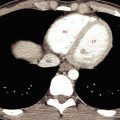
Not surprisingly the CT images must correlate with the patient’s symptoms. Disk material may demonstrate a mass effect on the thecal sac or a nerve root and may not be clinically symptomatic ( Fig. 20.4 ).

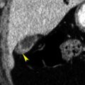
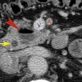
The presence of a protrusion should prompt a search for a sequestration. Failure to recognize such an abnormality can lead to failed back surgery. A sequestration should be suggested when disk material (soft tissue higher in density than the thecal sac) is identified caudal or cephalad to the level of the disk space ( Fig. 20.5 ). If the soft tissue is isodense to the thecal sac, it most likely represents a perineural cyst, Tarlov cyst, or conjoined nerve root. A Tarlov cyst is a perineural cyst and represents an enlarged nerve root sheath. It is a normal variant and rarely a cause of symptoms ( Fig. 20.6 ). Tarlov cysts can become large and erode bone as a result of cerebrospinal fluid (CSF) pulsations.


A conjoined nerve root is a congenital anomaly of two nerve roots exiting the thecal sac together instead of individually. The two nerve roots traverse the lateral recess together and appear as a density similar to that of the thecal sac on CT. A free fragment can have a similar appearance but will have higher attenuation compared with the thecal sac and conjoined nerve roots. The conjoined roots will invariably exit through their appropriate foramen ( Fig. 20.7 ). An “empty” foramen is not encountered. Conjoined nerve roots are associated with a slightly wider lateral recess than on the contralateral side. Conjoined roots occur in 1% to 3% of all patients and are incidental findings with no reported symptoms. The importance of their recognition is to avoid erroneous diagnosis of these normal variants as disk extrusions, which can result in explorations for free fragments and potential unfortunate neural damage during surgery. By noting density differences between conjoined roots and free fragments, the radiologist can avoid errors.

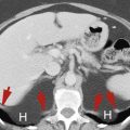
A lateral disk is a disk protrusion that occurs lateral to the neuroforamen and is one of the more commonly missed disk protrusions simply because it is overlooked. The search pattern should always include the region lateral to the neuroforamen. A lateral disk has huge implications for the surgeon. First, a lateral disk will irritate a nerve root that has already exited the neuroforamen and will therefore mimic a disk protrusion at a more cephalad level. For example, if a disk protrusion is present posteriorly at the level of L4–L5, it will usually have a mass effect on the L5 nerve root within the thecal sac. However, the L5 root can also be irritated by a lateral disk protrusion at the level of L5–S1. Therefore, if it is overlooked, such a disk protrusion can result in surgery at the level of the wrong disk space (in the example provided, incorrect surgery would be at the L4–L5 level) ( Fig. 20.8 ). This situation is particularly problematic in patients with multilevel disk abnormalities when one is attempting to determine the proper surgical level. Another important surgical implication for lateral disks is that a lateral disk does not require a laminectomy because it can be approached from outside the osseous central canal. The location of a lateral disk is not an area that a surgeon would normally explore. Lateral disks occur in less than 5% of patients but should be part of the search pattern in every patient at each disk level. The radiologist plays an enormous role in the ability to assess these findings and provide a necessary road map for surgical intervention.

Spinal Stenosis
Spinal stenosis has been classically divided into two types, congenital and acquired. Patients who experience congenital stenosis include achondroplastic dwarfs, patients with Morquio disease, and individuals born with a congenitally small thecal sac who have idiopathic spinal stenosis. Acquired stenosis includes osseous abnormalities that result in central canal narrowing such as degenerative joint (facet) disease with or without degenerative disk disease, posttraumatic stenosis, postsurgical stenosis, Paget disease, and calcification of the posterior longitudinal ligament.
A preferred classification for spinal stenosis is based on anatomic location. Stenosis can be described as central canal stenosis , neuroforaminal stenosis , or lateral recess stenosis . In each of these areas the most common cause of stenosis is osteoarthrosis of facet joints or disk disease as classified earlier.
Central Canal Stenosis
For decades, radiologists have been asked to measure the central canal to diagnose spinal stenosis. Discordance in the size of the bony canal and the thecal sac must be present for stenosis to be clinically manifest. A simple measurement of the central canal (without reference to the size of the bone canal) does not address the “fit” of the thecal sac within the canal, so such measurements are virtually meaningless. An exception to this situation may be the cervical spine, for which a narrow central canal has been correlated with increased risk of spinal cord injury in football players.
The most useful CT criteria for diagnosing central canal stenosis are obliteration of the epidural fat and flattening of the thecal sac. Both of these findings can be present without symptoms of spinal stenosis, and therefore stenosis can only be suggested by the radiologist, and clinical correlation is required.
The most common cause of central canal stenosis is secondary to facet arthrosis, which results in hypertrophy of the facet joints and encroachment of the central canal and lateral recess ( Fig. 20.9 ). Another common cause of central canal stenosis is “hypertrophy” of the ligamentum flavum. The ligamentum flavum does not actually hypertrophy, but rather buckles inward because of facet slippage and associated narrowing of the disk space. Because this condition represents soft-tissue encroachment, measurements of the size of the bone canal would not reflect this process, which is another reason why measurements are not reliable indicators of spinal stenosis.

Paget disease affecting a vertebral body, which occurs less often now than in the past, involves enlargement of the vertebral body and can occasionally result in central canal stenosis, as can ossification of the posterior longitudinal ligament. It has been reported that up to 25% of patients with diffuse idiopathic skeletal hyperostosis, a common entity in individuals older than 50 years, have ossification of the posterior longitudinal ligament ( Fig. 20.10 ). Other causes of central canal stenosis include trauma and postoperative changes.

Neuroforaminal Stenosis
The causes of neuroforaminal stenosis, similarly to those of central canal stenosis, can be diverse but are usually caused by osteophytes emanating from the vertebral body or from the superior articular facet. Disk protrusions and postoperative scarring can also occur in the foramen.
The nerve root exits the central canal in the superior aspect of the neuroforamen. Encroachment in the inferior aspect of the foramen, near the disk space, is an infrequent cause of clinical problems. The nerve root is immobile in the neuroforamen. Therefore even a small amount of stenosis in the superior aspect of the foramen can cause severe clinical symptoms, whereas severe stenosis of the inferior aspect of the foramen may result in no symptoms at all. For these reasons, the amount of narrowing of the neuroforamina often does not correlate with clinical findings.
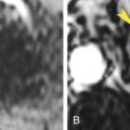
Although many believe that sagittal reformatted images through the neuroforamen are adequate for identification of stenosis, axial images are by far more reliable in fully demonstrating the degree of neuroforaminal stenosis and its cause. The neuroforamen and the nerve root can be seen in their entirety with axial images, whereas a single reformatted sagittal image will show volume rendering of the axial slice ( Fig. 20.11 ).

Related posts:

Stay updated, free articles. Join our Telegram channel

Full access? Get Clinical Tree


