Introduction
The advent of increasing numbers of rows of detectors has expanded the utility for CT technology. Multidetector CT (MDCT) has the ability to produce near-isotropic voxel images that allow multiplanar reformations and faster data acquisition. This technique is particularly valuable in the setting of trauma, for which conventional radiographs can be difficult to obtain because patients may be unable to comply with positioning requirements. Volume-rendered spiral CT can result in significant savings in terms of patient time spent in the radiology department. This technique also provides useful information for appropriate treatment and surgical planning by displaying three-dimensional spatial relationships in a two-dimensional image.
CT has two major roles in the evaluation of musculoskeletal trauma: (1) to define or exclude a fracture that was equivocal on conventional radiographs and (2) to determine the extent of a previously diagnosed fracture to assist in guiding therapy. In both trauma and nontrauma settings, spiral CT can provide information regarding soft-tissue abnormalities and demonstrate the osseous anatomy, particularly in anatomically complex areas such as the spine, pelvis, and scapula, for which conventional radiography may be limited.
Optimization of scanning techniques depends on the clinical question being addressed and the anatomic location to be examined. Small areas of interest combine narrow collimation (1–2 mm) and a pitch of 1 to 1.5 with small reconstructed increments (1 mm). Large areas of interest can be examined with wider collimation (3 mm) and a pitch of 1 to 2 with reconstruction every 2 to 3 mm.
There is considerable interest in CT dose reduction. In some circumstances, such as imaging of metallic prostheses, the exposure factors (peak kilovoltage and tube current) cannot be reduced without image quality being affected. The patient dose can be limited by careful positioning of the anatomic structure and limiting the area to be scanned. Low-kilovoltage techniques have been described for extremity and pelvis imaging without significant degradation of images. The polytrauma patient dose can be decreased by making a single pass of the chest, abdomen, and pelvis rather than scouting and scanning each region separately.
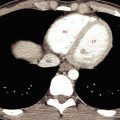
In the setting of trauma, MDCT is used to assess other body regions, and studies have shown that the spine can be included as part of the scan. Because of the high-quality two- and three-dimensional images, adequate images of the thoracic and lumbar spine can be obtained from chest and abdominal CT data ( Fig. 19.1 ).

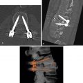
Three-dimensional reconstructions are often performed for fractures of the acetabulum, scapula, and calcaneus and for complicated fractures of the pelvis to assist with surgical planning ( Fig. 19.2 ).

According to the current American College of Radiology appropriateness criteria, the use of radiography in patients suspected of having a cervical spine injury should be reserved for adult patients when MDCT is not readily available, indicating that radiography should not be considered a substitute for CT. However, radiation exposure should always be minimized. Exposure during CT evaluations can be reduced by the use of automated exposure-control options according to the patient’s body habitus. Many manufacturers of CT equipment have developed dose-reduction solutions.
Cervical Spine Trauma
MDCT can detect 97% to 100% of cervical spine fractures, compared with 60% to 70% for conventional radiography. MDCT is widely used to complement conventional radiography for examination of the cervical spine following blunt trauma. Before helical scanning became available, conventional radiographs were the only radiologic means of imaging the cervical spine to exclude or diagnose injury following blunt trauma. The limitations of conventional radiography include poor visualization of areas with overlapping structures and the presence of other disease such as osteoarthrosis or rheumatoid arthritis or superimposed artifacts such as an endotracheal tube ( Fig. 19.3 ). In addition, the lower cervical and upper thoracic spine can be difficult to image on conventional radiographs for similar reasons and is well visualized by MDCT ( Fig. 19.4 ).


Importantly, in the clinical setting of spine fusion, either with hardware or secondary to ankylosis from ankylosing spondylitis or diffuse idiopathic skeletal hyperostosis, in a patient who presents with suspected injury after blunt trauma, a search for a fracture must include CT with reformatted images ( Fig. 19.5 ).

The detection accuracy for ligamentous injury of MDCT is not clearly documented, and magnetic resonance imaging (MRI) is highly sensitive in detecting these injuries.
Thoracic Spine
The thoracic spine is demonstrated nicely with reformatted images for chest-abdomen-pelvis CT in the setting of blunt trauma. CT can readily demonstrate a compression fracture (isolated to the vertebral body) from an unstable fracture involving the posterior elements, thus requiring surgical intervention ( Fig. 19.1 ). An unstable fracture involving the posterior elements is seen on conventional radiographs as widening of the interpedicular distance. As stated earlier and worth reiterating, for a patient who has fusion of the thoracic spine and presents with back pain after blunt trauma, a fracture must be sought with use of CT with reformatted images. An additional utility of CT is assessment of the presence of an underlying lesion that may not be appreciated with conventional radiography. A pathologic fracture can more readily be diagnosed and the extent of the pathologic process more accurately determined ( Fig. 19.6 ).

Lumbar Spine
Compression deformities of the lumbar spine are regularly seen on routine spine evaluation with conventional radiographs. When such an observation is made in the setting of trauma, an acute fracture is difficult to exclude as a cause, particularly if the patient is experiencing pain referable to this area. Cross-sectional imaging can aid in diagnosing fractures of the vertebral body. If a fracture is suspected on screening of the thoracolumbar spine during a CT assessment of the chest and abdomen/pelvis for internal organ injury, a repeated scan for specific evaluation of thoracic or lumbar injury may be necessary ( Fig. 19.7 ).

CT examination provides accurate depiction of the extension of fractures into the posterior elements and of fracture fragments into the spinal canal. Volume rendering can provide additional assessment of the extent of the fracture. If the patient has neurologic symptoms, MRI can be performed as a complementary examination.
In the lumbar spine, spondylolysis (pars interarticularis defect) is a posttraumatic entity that is clearly shown by CT. A pars interarticularis defect can be a result of an acute injury or secondary to repetitive stress changes through the osseous pars. Pars defects can be readily identified in an axial slice at the mid vertebral body. Other structures present at this level include the basivertebral plexus, identified in the posterior mid vertebral body at the same level where the pedicles are also identified. The lamina should be a continuous bony ring at the midbody slice, and a defect in the osseous ring is a spondylolysis ( Fig. 19.8 ). A pars interarticularis break can be overlooked, particularly if the defect is smooth along its margins and resembles facet joints. For this reason, any defect in the bony ring that occurs on a slice that includes the basivertebral plexus is a spondylolysis until proven otherwise. Another way to identify a pars interarticularis defect is to recognize that facet joints should not be present on every axial image obtained through the vertebral body. If facet joints are noted on each image through the vertebral body, a pars interarticularis defect is likely.

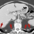
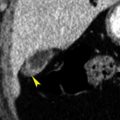
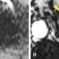
Imaging with CT can also assist in identifying the presence of a pathologic fracture. The presence of a superimposed lytic or blastic lesion in the setting of a collapsed vertebral body can be readily ascertained with cross-sectional imaging, and the pattern of the trabecular arrangement can help in identifying a pathologic fracture from multiple myeloma/plasmacytoma ( Fig. 19.9 ). Patients with preexisting conditions such as a primary malignancy may also experience blunt trauma, and thus the pattern of the fracture and the appearance of the vertebral body and its trabeculae must be evaluated in all settings of trauma.

Hip And Pelvis
After a fracture has been determined or is suspected on conventional radiography, or noted on chest-abdomen-pelvis trauma CT, dedicated CT through the pelvis is recommended for further characterization ( Fig. 19.10 ). CT will assist in identifying other occult pelvic ring fractures not identified on the initial radiographs as well as detailing the appearance of the fracture about the hip. If a patient has sustained a hip dislocation, CT on reduction is recommended to exclude intra-articular fracture fragments or loose bodies and assist with surgical planning ( Fig. 19.11 ) . If intra-articular fracture fragments or loose bodies go undetected, they may lead to accelerated articular cartilage destruction as a result of irregular joint articulation. Multiplanar reconstruction capabilities reduce the need for additional radiographs, thus decreasing the radiation dose to the patient.


Sacral stress fractures and insufficiency fractures have a characteristic appearance on CT. Sacral stress fractures occur most often in the athletic population secondary to abnormal stresses across normal bone. This has been described in long-distance runners, for example. CT will demonstrate a fracture line parallel to the sacroiliac joint. Callus formation along the fracture may also be seen as linear sclerosis. It is important to assess the sacrum on lumbar spine CT in patients being imaged for low back pain. In this patient population, in particular, sacral stress fractures may mimic lumbar disk disease.
Sacral insufficiency fractures occur as a result of normal stresses through abnormal bone and are seen in osteoporotic patients and those who have had pelvic radiation therapy that included the sacrum in the radiated field. The fracture lines parallel the sacroiliac joint and can be bilateral. Recognition of the linear fracture line excludes metastatic disease as a cause of back pain in this patient population ( Fig. 19.12 ).