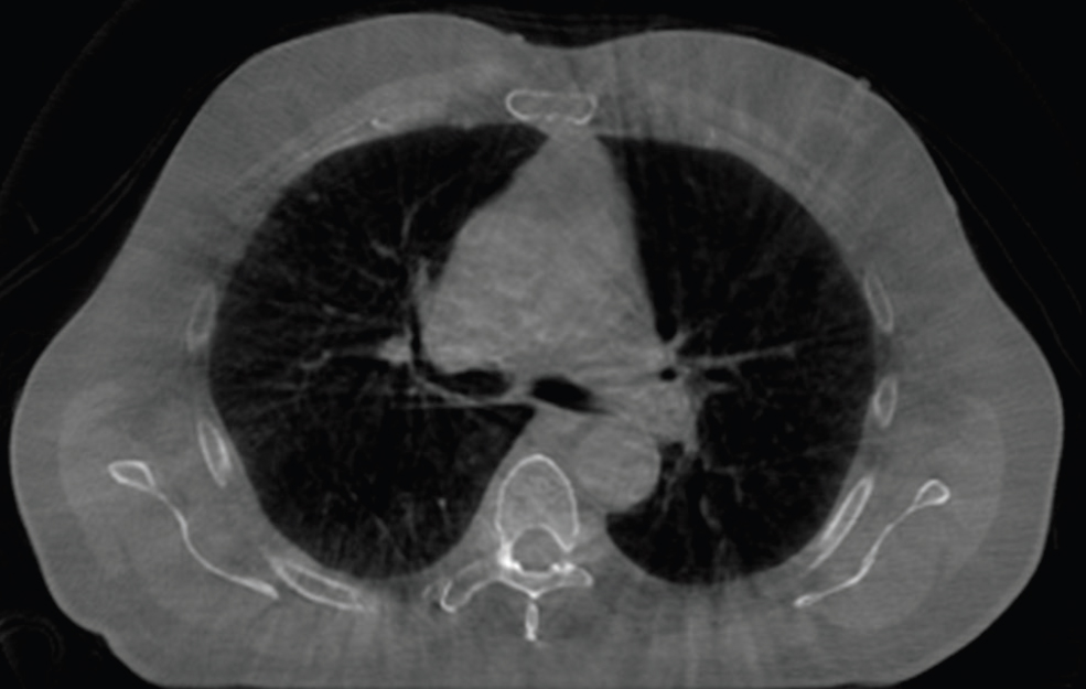
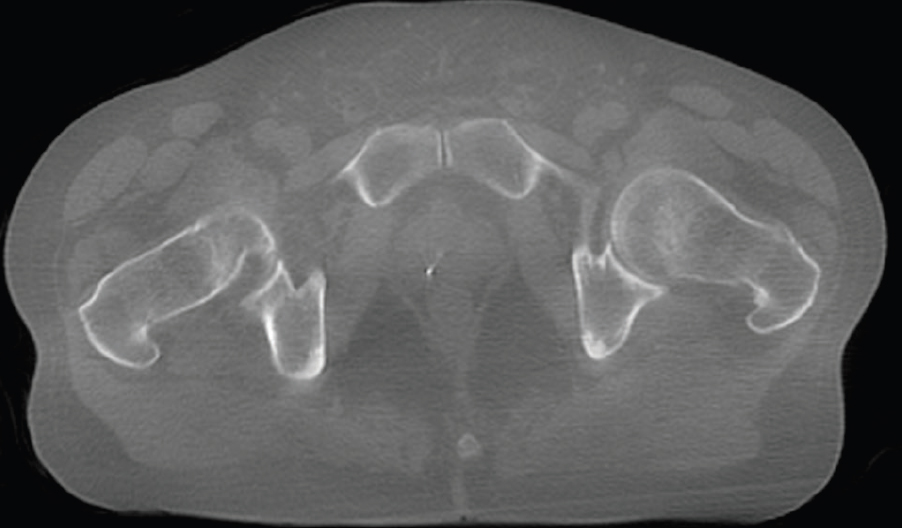
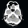
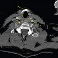
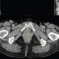
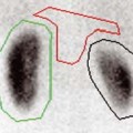
Since its inception in the 1970s, the CT scanner has steadily improved image quality, speed of acquisition and radiation safety. With the rapid development of technology, any description of current ‘state of the art’ equipment is doomed to obsolescence at time of printing and is beyond the scope of this text. The role of CT in radiotherapy in recent years, however, has expanded from its origins as the source of localisation data for treatment planning and is now the gold standard tool for treatment verification. Separate CT scanners in the treatment room or, more commonly, integrated with the treatment equipment can produce diagnostic-quality images to help direct treatment fields with increased accuracy; this process is known as Image-Guided Radiotherapy (IGRT). This technology makes it possible to take daily images that can inform online corrections and thus ensure radiation is delivered correctly, often without needing to move the patient. Despite initial concerns about imaging doses, sophisticated dose reduction measures have enabled low-dose volumetric data acquisition in the region of 10–50mGy per image (Steiner et al. 2013). For an overview of the increasingly varied role of cone beam CT in radiotherapy, the reader is referred to Srinivasan’s useful 2014 review paper. Although modern IGRT hardware is increasingly combined with automatic or semi-automatic image registration tools, it is still important for treatment staff to provide clinical input. It may, therefore, be of interest to the reader to examine some of these CT-based images with a view to appreciating how they differ from diagnostic images and applying image interpretation skills to them. Offering the nearest approximation to diagnostic quality CT images, the principle of cone beam imaging using kilovoltage generators and imagers is well-established. ‘Cone beam CT (CBCT)’ refers to the use of a wide fan of x-rays that obtain volumetric CT data in one rotation, as opposed to a series of single slice ‘fan beam’ acquisitions. The kilovoltage tubes and image intensifier panels are usually fixed orthogonally to the treatment beam axis. Use of kilovoltage ensures that the dominant photoelectric absorption process produces high contrast images. Although use of a wide cone beam allows a relatively large volume to be imaged, the diverging photons across a range of planes cause greatly increased scatter compared to a diagnostic fan beam image. The other major drawback to this technique, compared to a conventional CT scanner, is the length of time taken for image acquisition, with gantry rotation speed being limited for safety reasons. This increased time can produce movement artefacts and blurring. Despite these challenges, modern equipment (such as anti-scatter grids or bowtie filters as well as sophisticated scatter compensation or correction software) can still provide excellent images. Figure 6.1.1 illustrates a kilovoltage cone beam image of a male pelvis. When compared to the images in Chapter 2, it can be seen that the image lacks the sharp clarity of that produced by a diagnostic scanner. There is evidence of blurring and soft tissue definition is not as precise, for example muscle striation. Despite this, the reader should by now be able to identify bony structures, bladder, rectum, vas deferens, obturator internus muscle and external iliac artery and vein. Smaller structures, such as ureters and internal iliac vessels, are not so easily perceived, but overall the image is easily of sufficient quality for radiotherapy purposes. Figure 6.1.2 demonstrates the major drawback of linear accelerator-based cone beam CT with a CBCT image of the lung. Thoracic CBCT images are subject to motion artefacts and frequently exhibit blurring. This is because the vastly increased imaging time (compared to that enabled by enclosed circular gantry systems, such as traditional CT) encompasses several cycles of breathing. The effects of this differ between different regions of the lung and for different patients but can clearly be seen in Figure 6.1.2, where there are indistinct borders to the anterior lung. The reader should be able to identify the main bronchi and carina as well as both ascending and descending aorta with some confidence although individual muscle groups such as the pectorals are less well defined. Many of the visualised structures have some degree of double images or blurred edges. Note the reduced blurring at the posterior of the patient where motion is restricted by the couch top. Despite the motion effects, many of the structures can be identified, if not perfectly delineated. The lungs are obvious as ever and the position of the oesophagus can be seen hazily behind the carina. The sternum, thoracic vertebra, spinal cord and scapulae can also be seen easily. There are visible soft tissue structures peppering the lungs and these have been highlighted well using the lung window width and level settings. New developments in 4D image processing (Kincaid et al. 2013) mean that the cyclic breathing motion can be cancelled out to some extent. This process works by attempting to match images taken at the same stage of the breathing cycle, creating a range of images throughout the cycle. The disadvantage of this is that fewer gantry angles are used to create the CT image and general resolution is decreased. Figure 6.1.2

6.1Kilovoltage Cone Beam CT
![]()
Stay updated, free articles. Join our Telegram channel

Full access? Get Clinical Tree


