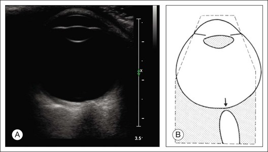
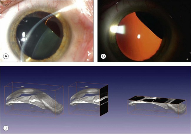
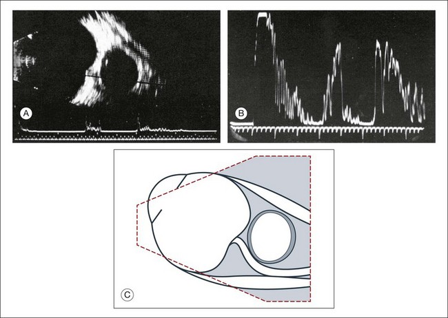
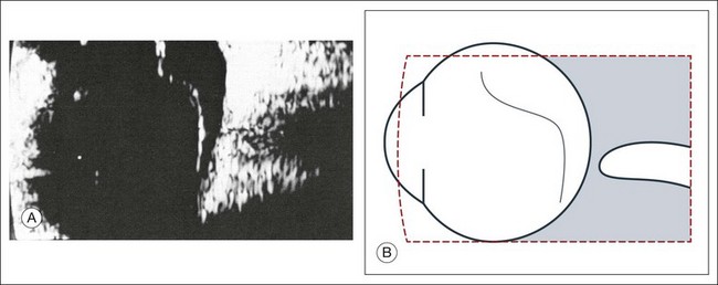
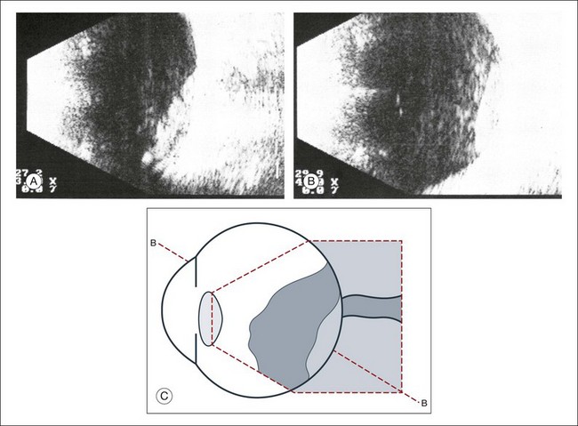
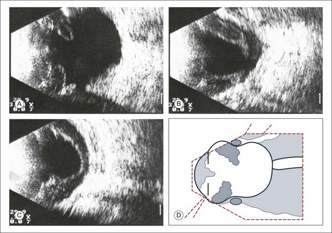
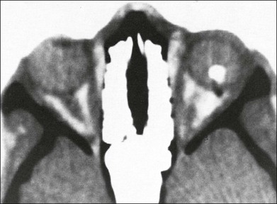
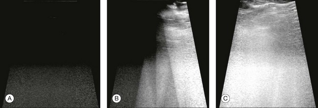
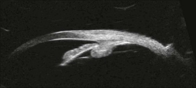
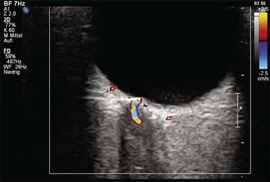
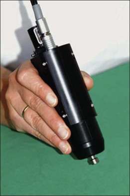
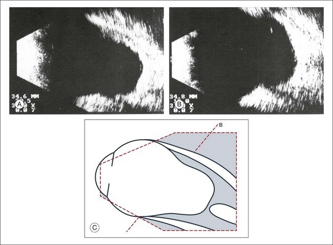
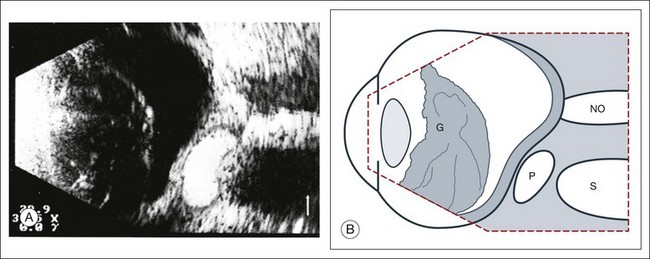
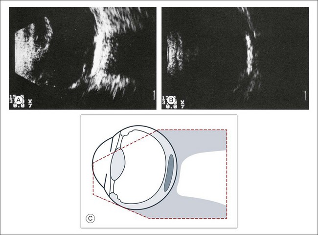
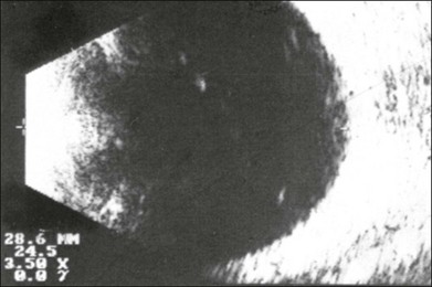
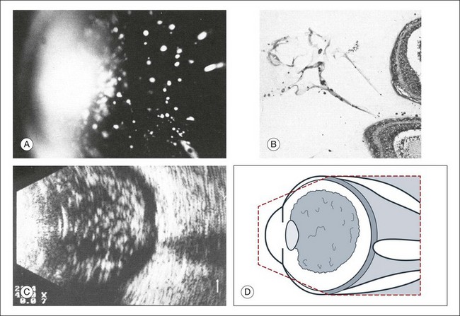
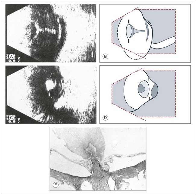
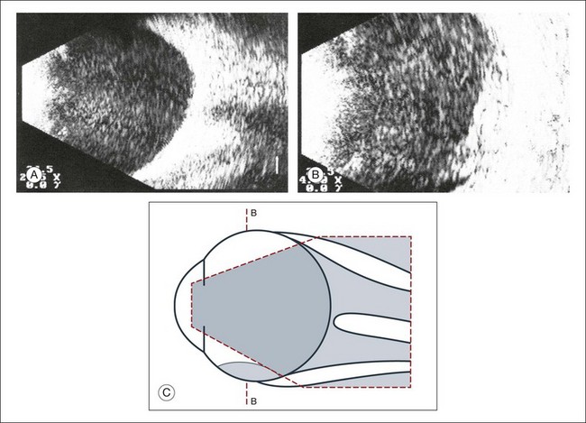
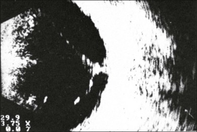
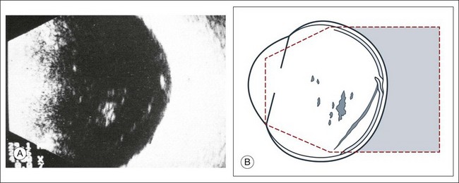
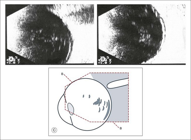
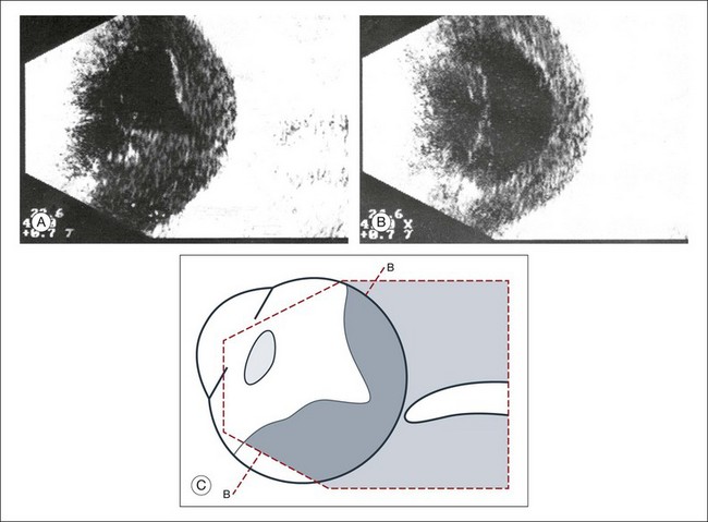
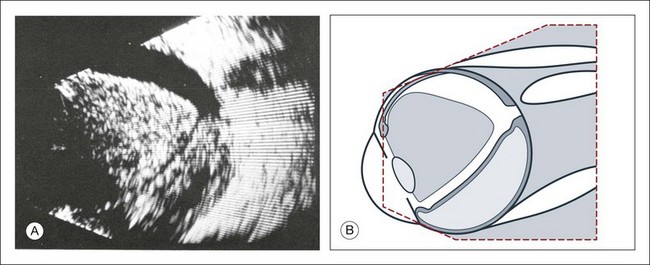
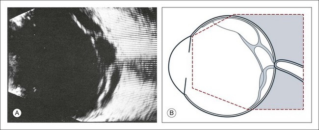
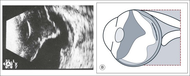
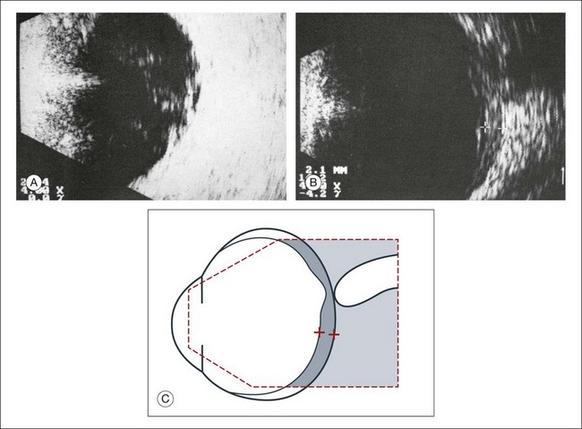
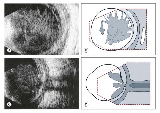
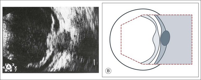
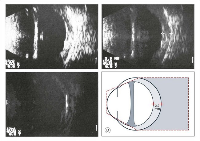
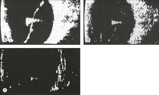
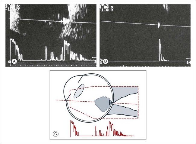
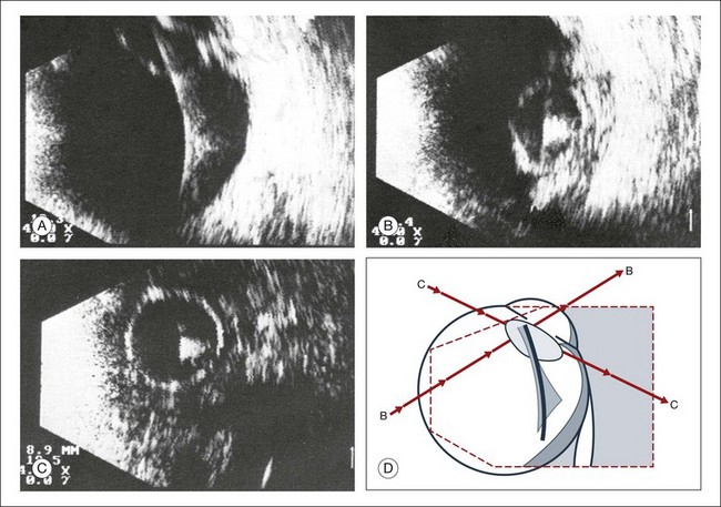
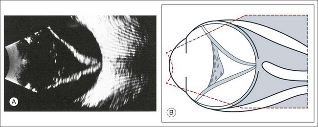
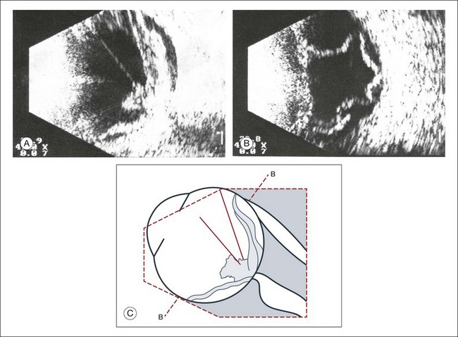
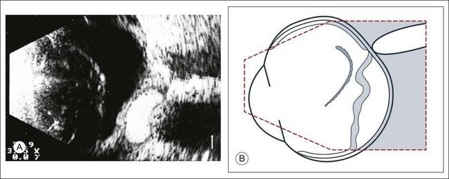
Chapter 9 In 1880, the Curie brothers first demonstrated that a difference in electric potential could be created by mechanically pressing opposing surfaces of a tourmaline crystal.1–7 This phenomenon is called the piezoelectric effect. This effect is the basis for ultrasound technology and was first applied in underwater sonar systems during World War II.8 During that same era, the medical community also adopted the use of ultrasound technology. Scientists realized the diagnostic potential of this technology when they were able to use acoustic wavelengths to study the consistency of a material without damaging the material itself. In 1949, Ludwig used ultrasound to detect gallstones in patients. The first publication on the use of ophthalmologic ultrasound appeared in the medical literature in 1956.9 By the mid-1970s, ophthalmologists were using ultrasound to determine axial length in a clinical setting. These measurements facilitated calculations of intraocular lens power which led to a revolution in cataract surgery.10 Further innovations came when Baum and Greenwood introduced their two-dimensional B-mode image to ophthalmology.11 Soon afterwards, Bronson et al.12 developed a hand-held contact transducer for this type of image acquisition which led to the rapid dissemination of ultrasound devices within ophthalmology clinics. The B-mode images could be used to delineate accurately retinal detachments, vitreous membranes, and choroidal tumors. In the early 1990s, new technology made it possible to image the anterior segment of the eye with devices that captured images at higher frequencies of 35–50 MHz. This improved image resolution four- to fivefold and is still the gold standard for analysis of certain anterior-segment diseases such as ciliary body effusions, infiltrates, and tumors. The ultrasound examination is performed with the patient in a reclined position. The frequency of the ultrasound cannot pass through air; therefore, a coupling medium is needed to transmit the sound waves from the transducer to the ocular tissues. A common coupling agent is methylcellulose (Fig. 9.1). The coupling agent is applied to the tip of the transducer probe, which is then placed on the patient’s anesthetized cornea. Fig. 9.1 Ultrasound images simulating the effect of transducer (A) without tissue-coupling agent, (B) with partial tissue-coupling agent, and (C) with a complete coupling agent, such as a gel-like contact substance. The reflected sound waves are recorded by the device and can be viewed as a two-dimensional image on the screen (Fig. 9.2). The ocular structures can be examined individually. The cornea is characterized ultrasonographically by two separate acoustic interfaces. The anterior chamber appears planoconvex in cross-section. The iris diaphragm cannot be satisfactorily imaged because of the limited lateral resolution power of the normal B-mode. A clear lens is acoustically empty and appears as an ellipsoid structure in axial sections. Similarly, normal vitreous does not give an acoustic signal; however, the presence of a detached posterior vitreous membrane presents an interface that can be imaged by increasing the amplification of the echo signal. The sclera is the most strongly reflecting structure on ocular ultrasonography. High-frequency echograms can be used for ultrasound biomicroscopy (UBM). The shorter wavelengths provide better resolution of the anterior structures of the eye, including the cornea, lens, aqueous (Fig. 9.3), and ciliary body (Fig. 9.4).13 High-frequency probes range from 50 to 100 MHz.14–16 The 50-MHz probe provides the best balance between depth and resolution for UBM technique. One limitation of this technique is that the shorter wavelengths, from the higher frequency, have poor depth of penetration. UBM cannot visualize structures deeper than 4 mm from the surface. Fig. 9.3 The ultrasound biomicroscopy images of the anterior segment in (A) a phakic and (B) a pseudophakic eye with multiple echo of implant surface. Fig. 9.4 Ultrasound biomicroscopy of the ciliary body.The shorter wavelengths are able to obtain high-resolution images of the anterior structures. UBM requires immersion of the transducer in a medium to transmit the higher-frequency wavelengths. Saline or methylcellulose can be used as the coupling agent and is held in place over the eye with the use of a custom cup during the examination. UBM is performed through open eyelids in order to obtain a good reflection signal. Images produced by UBM have a resolution of 30–40 µm, which is similar to that seen with a low-power microscope.17 Doppler images are obtained by using frequency shifts from acoustic reflections to measure movements within a tissue and flow conditions within vessels. These frequency shifts can be observed in tissue volumes of less than 10 mm. False color can be added to the images based on ultrasound frequency to distinguish between higher and lower flow states, which aids in the interpretation of the final result (Fig. 9.5). Fig. 9.5 Cross-sectional ultrasonogram through the posterior pole of the eye: color-coded signals from the central retinal artery (red) and the central retinal vein (blue) are displayed inside the optic nerve. Basic physics formulae can be used to calculate the speed of sound as it passes through various ocular tissues. This number can then be used to calculate distance measurements within the eye (Fig. 9.6). In order to obtain accurate measurements, the specific speed of sound of the different intraocular media, such as the lens, aqueous, and vitreous, must be known.18 These formulae provide precise measurements that can be used to measure intraocular tumors or to deduce the axial length of the globe for intraocular lens power calculations. Real-time three-dimensional (3D) and four-dimensional (4D) images are currently used in some medical specialties, including gynecology, obstetrics, and cardiology, but their use in ophthalmology is limited. 3D ultrasonic images can be produced from a series of scan planes.19–22 Silverman et al.23 characterized the ciliary bodies in rabbits and human subjects using 3D high-resolution ultrasound. In the authors’ laboratory a simple extension of the Ultrasound Biomicroscope Model 840 (Humphrey Instruments, Carl Zeiss Group) and VuMax UBM 35/50 (Sonomed) into a user-friendly 3D ultrasonic imaging system was developed (Figs 9.7 and 9.8).24–28 Fig. 9.7 Prototype of a handpiece for three-dimensional high-frequency scanning using the VuMax UBM 35/50 (Sonomed). Changes in the shape of the globe A staphyloma is an abnormal ectasia of the globe that involves uveal tissue. The ectasia typically has a smaller radius of curvature then the normal sclera of the globe. It can be identified on ultrasound by taking axial cross-sectional scans with the transducer probe (Fig. 9.9). Fig. 9.9 Staphyloma in a highly myopic eye (axial length 34.8 mm). (A) An axial section of the eccentric entrance of the optic nerve can be seen. (B) The misshapen globe is especially well demonstrated on a sectional plane which lies outside the optical axis. (C) Schematic drawing. Scleral buckle: A scleral buckle can create a posterior scleral deformity that looks similar to a staphyloma. It can be distinguished from a true staphyloma by a careful history or identification of the encircling band around the anterior sclera. Also, if silicone oil was used for repair, the higher index of refraction within the silicone oil can alter the reflectance of the ultrasound wavelengths, which might provide a false impression of globe deformation (Fig. 9.10). Fig. 9.10 (A) Scleral buckle produced by a silicone sponge explant. After placement of a scleral buckle, the deformity of the globe can be seen in an acoustic cross-section. Silicone explants almost completely reflect the ultrasound. They also cast an acoustic shadow. (B) Schematic drawing. NO, optic nerve; P, explant; S, sound shadow; G, syneretic, densified vitreous. Congenital microphthalmos is an abnormally small eye that can be associated with other ocular abnormalities. The main finding in microphthalmos is axial shortening. This can be identified with A-scan measurements. The B-scan mode can be used to obtain radial and transverse scans to identify abnormalities in the vitreous and posterior segment of the eye, which can also be associated features of microphthalmos. These features include the presence of a coloboma of the retina or optic nerve head, orbital cysts (Fig. 9.11), or persistent hyperplastic vitreous. Phthisis is defined as severe atrophy of the globe associated with hypotony. Phthisis is characterized ultrasonographically by a thickened outer scleral wall. Occasionally, calcification or ossification may be observed (Fig. 9.12). This may be due to degenerative processes and from metaplasia of the retinal pigment epithelium (RPE). In advanced cases of phthisis, the sclera and choroid can represent up to 70% of the total volume of the globe. The degree of thickening of the globe in chronic hypotony can be an indication of impending phthisis, but the precise thickness threshold for phthisis formation is unknown. Fig. 9.12 Circumscribed calcification in the ocular wall in advanced phthisis bulbi. (A) Echographically we find highly reflective changes in the ocular wall from calcification or ossification of the choroid which casts a shadow on the soft tissue located posteriorly. (B) These strong echoes can be selectively imaged by reducing the amplification. (C) Schematic drawing. Echographic examination can provide information on vitreous structure which is particularly useful when visualization of the posterior pole is poor due to anterior media opacities. Ultrasonographic findings allow the examiner to differentiate dot-, strand-, and membrane-like reflections (Fig. 9.13). Table 9.1 summarizes the most frequent conditions associated with pathologic changes in the vitreous. Fig. 9.13 Vitreous opacities. In maximal amplification, small heterogeneous spots can be seen echographically, even though the vitreous appears optically clear (left). They act as dot-like reflectors. Vitreous syneresis can appear as dot-like reflections which can be more pronounced in myopia or senile vitreous. During a symptomatic posterior vitreous detachment, the B-mode echo may demonstrate various stages of vitreous syneresis and may reveal the remaining adhesions of the hyaloid membrane to the retinal surface (Fig. 9.14). The calcium-containing lipids of asteroid hyalosis are suspended in the vitreous framework and act as distinctive sound reflectors (Fig. 9.15). They can demonstrate the dynamics of vitreous movements. Fig. 9.15 Asteroid hyalosis. (A) Slit-lamp microscopic photograph of the anterior vitreous space. (B) Histological image of asteroid hyalosis shows the calcium crystals adherent to the vitreous scaffold. (C) B-scan cross-section of the crystals, which represent good reflectors for the ultrasound. There is always an echo-free retrovitreal space seen near the ocular walls. (D) Schematic drawing. Synchysis scintillans: In synchysis scintillans the vitreous is filled with cholesterol crystals. Unlike asteroid hyalosis, these crystals are not suspended within the vitreous but instead float freely in the vitreous space. When the globe moves, the crystals appear in the center of the vitreous body. This clinical picture may resemble asteroid hyalosis, but after a few seconds the cholesterol crystals will sink toward the bottom of the cavity. A-mode images display characteristic flickering spikes from the reflections of these crystals. The primary vitreous contains the tunica vasculosa lentis, which is part of the fetal vasculature system. During development, the tunica vasculosa lentis emanates from the optic nerve head and supplies the posterior lens. This structure should involute prior to birth. Failure of the primary vitreous to regress fully is termed persistent hyperplastic primary vitreous. As mentioned earlier, this can be associated with microphthalmos and cataract formation in the newborn. The condition persistent hyperplastic primary vitreous can be ultrasonographically characterized by two features. The first is a strand of membrane that extends between the posterior surface of the lens and the area of the optic nerve head. The second is the reduced axial length of the globe from microphthalmos on ultrasound biometry (Fig. 9.16). If the anomaly is only mild, the lens may be clear at birth but may become cataractous when the posterior lens capsule ruptures. Fig. 9.16 (A–D) Posterior polar cataract in persistent hyperplastic primary vitreous (PHPV). An ultrasonographically demonstrable strand attached to the posterior lens pole points is suspicious for PHPV (A). Frontal plane taken temporally with maximal adduction of the globe (C). (B,D) Schematic drawings. The dark, hatched parts correspond to the opaque area of the posterior cortex and posterior capsule in a child with severe PHPV. (E) Histological section of PHPV as seen at optic nerve head with loupe magnification. An acute vitreous hemorrhage is an important indication for ultrasonography. Acute hemorrhages can fill the vitreous cavity with small opacities from the particles of the red blood cells. These opacities usually accumulate after a few hours in the lower circumference of the vitreous base (Fig. 9.17). Fig. 9.17 (A) Conspicuous bleeding into syneretic vitreous; erythrocytes within the vitreous create reflective opacities. A static picture may give the impression of a solid lesion. (B) After a few hours the opacities usually accumulate in the lower aspect of the vitreous cavity. (C) Schematic drawing. If a detachment of the posterior hyaloid membrane precedes a vitreous hemorrhage, the erythrocytes frequently precipitate on to a vitreous strand (Fig. 9.18). This strand may be responsible for the development of a retinal tear, and its traction can be demonstrated directly in acoustic sectioning (Fig. 9.19). A circumscribed thickening of the ocular wall in cross-section may indicate the presence of a retinal operculum (Fig. 9.20). This area should be localized echographically and then carefully scrutinized with ophthalmoscopy if possible. Fig. 9.18 Fresh vitreous hemorrhage. In a cross-sectional echogram the vitreous framework converges towards the ocular wall. Blood precipitates increase the acoustic reflectivity of the vitreous. Traction has to be assumed where the vitreous is in contact with the ocular wall. Fig. 9.19 (A) Recent vitreous hemorrhage. The low reflecting membranes float freely with ocular movement. A newly formed horseshoe tear may be present at their connection point to the wall. (B) Schematic drawing. Fig. 9.20 (A,B) Recent vitreous hemorrhage. Erythrocytes have precipitated on to the partly detached posterior hyaloid membrane, increasing its acoustic reflectivity. (C) Schematic drawing. In larger hemorrhages, the blood can also disseminate into multiple pre-existing vitreous compartments. In the early phase of this process, the erythrocytes will collect in the retrovitreal space (Fig. 9.21). The retrovitreal space may completely clear after a few days or weeks due to its high fluid exchange rate; however, blood on the vitreous framework absorbs much more slowly (Fig. 9.22). Fig. 9.21 (A) Vitreous hemorrhage with posterior vitreous detachment emphasizing the retrovitreal space. (B) In the early stage after the hemorrhage, erythrocytes accumulate in the retrovitreal space. They may ensheath the part of the vitreous that was free of blood and had a normal structure. (C) Schematic drawing. Fig. 9.22 The retrovitreal space may completely clear after a few days or weeks due to its high fluid exchange rate; however, blood on the vitreous framework or located subretinally absorbs much more slowly (A). (B) Schematic drawing. Vitreous hemorrhage from neovascularization: Hemorrhages that develop from proliferative changes in patients with diabetic retinopathy and retinal neovascularization will always be accompanied by pathologic changes in the vitreous. Vitreous membranes tent rectilinearly between the adhesions to the retina. The normal aftermovements that should occur in the vitreous after eye movements are extinguished in the presence of peripheral neovascular tufts. The vitreous tufts create adhesions that encircle the posterior pole. This is an ominous sign, which is indicative of early retinal tractional detachment from these circular adhesions (Fig. 9.23). Choroidal neovascularization from age-related macular degeneration will have hemorrhage in multiple layers of the eye (Fig. 9.24). Fig. 9.23 (A) Beginning traction detachment at the posterior pole with vitreous contraction and proliferative diabetic retinopathy, which is hidden behind a diffuse vitreous hemorrhage. A springboard-like, taut, detached hyaloid membrane is still adherent to the retina at the posterior pole and has led to a traction detachment in several places. (B) Schematic drawing. Fig. 9.24 (A) Extensive vitreous hemorrhage from disciform macular degeneration. The blood dissipates into the preretinal or intrachoroidal space, into the area of the macular lesion and into the detached vitreous. The retrovitreal space is echo-free because of its high fluid exchange. (B) Schematic drawing. Terson’s sign is a multilayered, intraocular hemorrhage at the posterior pole that typically occurs after blunt trauma to the head. This is usually accompanied by a subarachnoid hemorrhage. If the posterior hyaloid membrane is still attached, the preretinal bleeding will slowly diffuse into the formed vitreous (Fig. 9.25). This can damage the underlying retina and may be an indication for an early vitrectomy. Ocular infection that extends toward the anterior segment or results in a hypopyon formation will have changes within the anterior vitreous space that are demonstrable on ultrasound. A thickening of the retina or choroid can be seen if the inflammation penetrates to the outer layers of the globe (Fig. 9.26). After only a few hours, these changes may involve the entire vitreous body (Fig. 9.27). If panophthalmitis follows a perforating injury, ultrasound evaluation can detect a local reaction at the entrance point of the infection (Figs 9.28 and 9.29). Fig. 9.26 (A,B) Panophthalmitis after an intraocular operation. Widening of the ocular wall to about 2.1 mm indicates inflammatory choroidal infiltrates. (C) Schematic drawing. Fig. 9.27 Vitreous abscess that caused a bacterial orbital inflammation. (A) B-scan ultrasonography demonstrates a highly reflective vitreous body which is partly detached from the retina. (B) Schematic drawing of this image. (C) Posterior pole shows infiltration of Tenon’s space and widening of the optic nerve sheath. (D) Schematic drawing. Fig. 9.28 Posttraumatic intraocular infection starting from the side of perforation. (A) B-scan ultrasonography demonstrates localized thickening of the ocular wall indicating the side of the perforation. The vitreous is filled with inflammatory cells, the posterior hyaloid is thickened, and there is a localized retinal detachment. (B) Schematic drawing. Inflammatory and hemorrhagic vitreous changes cannot be differentiated on the basis of ultrasonographic findings alone. Both conditions may cause densification of pre-existing vitreous structures with subsequent shrinkage of the vitreous; tractional detachment of the retina can occur, especially if there are postinflammatory adhesions between the vitreous and retina. In chronic uveitis, an early and complete posterior vitreous detachment can occur and cause the formed vitreous to shrink and form a frontal membrane that extends across the vitreous base (Fig. 9.30). If this membrane adheres to the ciliary body, it may detach the ciliary body and produce subsequent ocular hypotony.29 Fig. 9.30 Phthisis oculi in chronic panuveitis. (A) The vitreous has shrunk to form a frontal membrane of high acoustic reflectivity. The ocular wall is widened to 2.9 mm. (B) Using linear amplification, the various layers of the ocular wall have become clearly outlined. (C) Isolated areas of the ocular wall show high acoustic reflectivity, which indicates calcification of the choroid or in the sclera. (D) Schematic drawing highlighting wall thickness. Intraocular foreign bodies induce a change in echo reflectivity which is based on the composition of the material (Figs 9.31–9.33). The change in the reflectivity on the image should be a helpful clue in the localization of the foreign body within the globe; however, this is not always the case since the foreign bodies can also create signal artifact on echograms that can make identifying their exact location difficult. For example, large metallic foreign bodies have significant artifacts from strong reflected signals that can distort their true location. In addition, foreign bodies from trauma can be associated with air bubbles within the vitreous that can mask the presence of the nearby foreign body within the acoustic shadow (Fig. 9.34). Fig. 9.31 (A) Metallic foreign body in the vitreous with total retinal detachment. (B) The foreign-body spike is characterized by its high amplitude and repetitive echoes. (C) With reduced sensitivity the foreign body can almost be imaged as an isolated echo. Fig. 9.32 Acute perforating injury with intraocular metallic foreign body. (A) Ultrasonographically, there is a typical foreign-body echo with repetitive spikes in the vitreous about 2 mm in front of the ocular wall. (B) Decreasing the amplification displays the foreign-body echo as the only intraocular structure remaining visible on ultrasonography. (C) Schematic drawing. Fig. 9.33 (A) Intraocular foreign body of a piece of wire. (B) The anterior end of the wire remained visible in the lens. Cross-sectional image taken temporally with maximal adduction of the globe. (C) Frontal section through iris and lens. (D) Schematic drawing. In a retinal detachment, the neurosensory retina separates from the RPE layer. This development allows fluid to collect in the potential space between these two layers. The detached neurosensory retina appears as a membrane in the vitreous space on ultrasound. Partial retinal detachments may still maintain connections to the optic nerve or ora serrata since these areas have the strongest connections to the retina. Identification of these connections on ultrasound can distinguish a partial retinal detachment from a vitreous or choroidal detachment, which would have different anatomical connections (Fig. 9.35). A complete retinal detachment can form a funnel shape due to the retina folding in the center of the globe. Fig. 9.35 (A) Complete retinal detachment extending between the optic nerve head and the ora serrata. Heterogeneous material in the anterior vitreous is a sign of vitreous reaction. (B) Schematic drawing. Complicated retinal detachments with severe pathology can make it difficult to identify all the structures on ultrasound (Fig. 9.36). For example, in severe trauma cases that are associated with proliferative vitreoretinopathy or in advanced diabetic disease associated with proliferative retinopathy, the membranes formed within the vitreous can appear similar to a true retinal detachment. The following questions can guide the ultrasound examination of the retina in order to differentiate these common causes of vitreous membranes: Fig. 9.36 Development of a traction detachment with massive vitreous retraction. (A) Flat subtotal retinal detachment with folds; rigid vitreous strands. (B) In a frontal section, multiple contacts of the retina to the ocular wall can be demonstrated. (C) Schematic drawing. • What is the spatial extent of the membrane? At which point is there contact with the ocular wall? • What is the shape of a cross-section of the membrane, especially in the optic nerve head area? • How great is the difference of the spike from the membrane in question to the scleral standard or to the echo from a standard reflector? These questions should be clarified in the following way: 1. What is the spatial extent of the membrane? At which point is there contact with the ocular wall? A recent rhegmatogenous retinal detachment can be characterized in cross-section by a membranous structure of high reflectivity that converges in an acute angle toward the ocular wall. If the imaged acoustic section is centered on the optic nerve head, then the border of the detached retina will be captured as it connects to the nerve head (Fig. 9.37). If the membrane passes over the optic nerve head instead of connecting to the optic nerve in the echo image, it is not a retinal detachment (Fig. 9.38). This feature can help identify retinal membranes form vitreous membranes. Fig. 9.37 (A) Sectoral retinal detachment. In acute retinal detachment, short aftermovements appear when the globe moves. These aftermovements extend like a whiplash from the area of the contact to the ocular wall. (B) Schematic drawing.
Diagnostic Ophthalmic Ultrasound
Ultrasound – past and present
Examination techniques
B-mode technique
High-frequency ultrasound technique

Doppler ultrasound
Ultrasound biometry
Three-dimensional reconstructions
Ultrasound in intraocular pathology
Staphyloma
Microphthalmos
Phthisis
Vitreous
Vitreous degeneration
Asteroid hyalosis
Persistent and hyperplastic primary vitreous
Vitreous hemorrhages
Terson syndrome
Intraocular infections
Vitreous inflammation
Intraocular foreign bodies
Retina
Acute retinal detachment
![]()
Stay updated, free articles. Join our Telegram channel

Full access? Get Clinical Tree


