chapter 20 Digital Image Processing in Nuclear Medicine
Image processing refers to a variety of techniques that are used to maximize the information yield from a picture. In nuclear medicine, computer-based image-processing techniques are especially flexible and powerful. In addition to performing basic image manipulations for edge sharpening, contrast enhancement, and so forth, computer-based techniques have a variety of other uses that are essential for modern nuclear medicine. Examples are the processing of raw data for tomographic image reconstruction in single photon emission computed tomography (SPECT) and positron emission tomography (PET) (see Chapters 16 to 18), and correcting for imaging system artifacts (e.g., Chapter 14, Section B, and Chapter 18, Section D). Another important example is time analysis of sequentially acquired images, such as is done for extracting kinetic data for tracer kinetic models (see Chapter 21). Computer-based image displays also allow three-dimensional (3-D) images acquired in SPECT and PET to be viewed from different angles and permit one to fuse nuclear medicine images with images acquired with other modalities, such as computed tomography (CT) and magnetic resonance imaging (MRI) (see Chapter 19). Computer-based acquisition and processing also permit the raw data and processed image data to be stored digitally (e.g., on computer disks) for later analysis and display.
In this chapter, we describe general concepts of digital image processing for nuclear medicine imaging. Additional discussions of specific applications are found in Chapters 13 to 19 and Chapter 21.
A Digital Images
1 Basic Characteristics and Terminology
Virtually all modern nuclear medicine images are recorded as digital images. This is required for computerized image processing. A digital image is one in which events are localized (or “binned”) within a grid comprising a finite number of discrete (usually square) picture elements, or pixels (Fig. 20-1). Each pixel has a digital (nonfractional) location or address, for example, “x = 5, y = 6.” For a gamma camera image, the area of the detector is divided into the desired number of pixels (Fig. 20-2). For example, a camera with a field-of-view of 40 cm × 40 cm might be divided into a 128 × 128 grid of pixels, with each pixel therefore measuring 0.3125 mm × 0.3125 mm. Each pixel corresponds to a range of possible physical locations within the image. If an event were determined to have interacted at a location x = 4.8 cm, y = 12.4 cm, the appropriate pixel location for this event would be
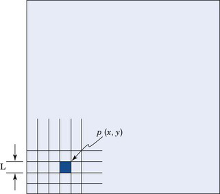
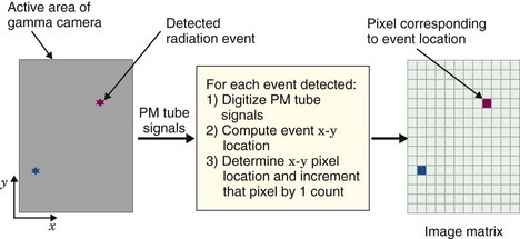
where int(x) denotes the nearest integer of x, and the pixels are labeled from 0-127 with the coordinate system defined as shown in Figure 20-2.
Depending on the mode of acquisition (discussed in Section A.4), either the x-y address of the pixel in which each event occurs, or the pixel value, p(x, y), is stored in computer memory. For 3-D imaging modes, such as 3-D SPECT or PET, individual events are localized within a 3-D matrix of voxels, and the reconstructed value in a voxel is denoted as v(x, y, z). Depending on how data are acquired and processed by the imaging system, the pixel or voxel value may correspond to the number of counts, counts per unit time, the reconstructed pixel or voxel value, or absolute radionuclide concentrations (kBq/cc or µCi/cc).
Although most interactions between the user and a computer system involve conventional decimal numbers, the internal operations of the computer usually are performed using binary numbers. Binary number representation uses powers of 2, whereas the commonly used decimal number system uses powers of 10. For example, in decimal representation, the number 13 means [(1 × 101) + (3 × 100)]. In the binary number system, the same number is represented as 1101, meaning [(1 × 23) + (1 × 22) + (0 × 21) + (1 × 20)], or (8 + 4 + 0 + 1) = 13. Each digit in the binary number representation is called a bit (an abbreviation for “binary digit”). In general, an n-bit binary number can represent decimal numbers with values between zero and (2n − 1).
Pixel depth also affects the number of gray shades (or color levels) that can be represented within the displayed image. In most computer systems in use in nuclear medicine, 8 bits equals a byte of memory and 16 bits equals a word of memory. The pixel depth, therefore, frequently is described as “byte” mode or “word” mode.*
2 Spatial Resolution and Matrix Size
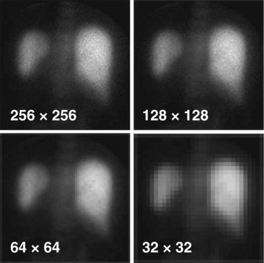
The spatial resolution of a digital image is governed by two factors: (1) the resolution of the imaging device itself (such as detector or collimator resolution) and (2) the size of the pixels used to represent the digitized image. For a fixed field-of-view, the larger the number of pixels, that is, the larger the matrix size, the smaller the pixel size (Fig. 20-3). Clearly, a smaller pixel size can display more image detail, but beyond a certain point there is no further improvement because of resolution limitations of the imaging device itself. A question of practical importance is, At what point does this occur? That is, how many pixels are needed to ensure that significant detail is not lost in the digitization process?
The situation is entirely analogous to that presented in Chapter 16 for sampling requirements in reconstruction tomography. In particular, Equation 16-13 applies—that is, the linear sampling distance, d, or pixel size, must be smaller than or equal to the inverse of twice the maximum spatial frequency, kmax, that is present in the image:
This requirement derives directly from the sampling theorem discussed in Appendix F, Section C.
Once this sampling requirement is met, increasing the matrix size does not improve spatial resolution, although it may produce a cosmetically more appealing image with less evident grid structure. If the sampling requirements are not met (too coarse a grid), spatial resolution is lost. The maximum spatial frequency that is present in an image depends primarily on the spatial resolution of the imaging device. If the resolution of the device is specified in terms of the full width at half maximum (FWHM) of its line-spread function (Chapter 15, Section B.2), then the sampling distance (pixel size) should not exceed about one third of this value to avoid significant loss of spatial resolution, that is,
Answer
A 64 × 64 image matrix results in a pixel size of 300 mm/64 = 4.69 mm. From Equation 20-2, this would be suitable for image resolution given by


The values calculated in Example 20-1 represent the approximate levels of imaging system resolution that could be supported without loss of imaging resolution for the specified image and matrix sizes. The practical effects of undersampling depend as well on the information contained in the image and whether it has a significant amount of actual spatial frequency content near the resolution limit of the imaging device. Practical experimentation sometimes is required to determine this for a particular type of imaging procedure.
3 Image Display
Digital images in nuclear medicine are displayed on cathode ray tubes (CRTs) or flat-panel displays such as liquid crystal displays (LCDs). In addition to their use at the site of the imaging device, displays are an essential component of picture archival communications systems (PACS) networks, for remote viewing of images (see Section C). The spatial resolution of the display device should exceed that of the underlying images so as not to sacrifice image detail. In general, the display devices used in nuclear medicine computer systems and in radiology-based PACS networks comfortably exceed this requirement. Typical high-resolution CRTs have 1000 or more lines and a typical LCD might have 1536 × 2048 elements.
Stay updated, free articles. Join our Telegram channel

Full access? Get Clinical Tree


