chapter 17 Single Photon Emission Computed Tomography
As discussed in Chapter 16, a rotating gamma camera can be used to acquire data for computed tomographic (CT) images. This approach to tomography, which is employed with radionuclides that emit single γ rays or multiple γ rays with no angular correlations, is known as single photon emission computed tomography (SPECT). In this chapter, we describe the design features and performance characteristics of SPECT systems. We also discuss some practical aspects of SPECT imaging and some of its major clinical applications. A second form of tomographic nuclear medicine imaging, positron emission tomography (PET), uses radionuclides that decay by positron emission. PET imaging systems and their characteristics are discussed in Chapter 18. Multimodality systems that combine SPECT or PET with x-ray CT are discussed in Chapter 19.
A SPECT Systems
1 Gamma Camera SPECT Systems
Almost all commercially available SPECT systems are based on the gamma camera detector that was described in detail in Chapters 13 and 14. A single gamma camera head, mounted on a rotating gantry, is sufficient to acquire the data needed for tomographic images. The gamma camera acquires two-dimensional (2-D) projection images at equally spaced angular intervals around the patient. These images provide the 1-D projection data needed for reconstructing cross-sectional images using the techniques described in Chapter 16. Typically, clinical SPECT images are reconstructed on a matrix of 64 × 64 or 128 × 128 pixels. Cross-sectional images are produced for all axial locations (slices) covered by the field of view (FOV) of the gamma camera, resulting in a stack of contiguous 2-D images that form a 3-D image volume.
The number of angular projections (or views) needed when using a standard parallel-hole collimator can be calculated using Equation 16-15. Because the resolution of a general-purpose parallel-hole collimator is approximately 1 cm at a distance of 10 cm from the collimator (see Fig. 14-16), the number of views required generally is between 64 and 128, for a FOV ranging from 20 to 60 cm in diameter. Although data acquired over an arc of 180 degrees are sufficient for tomographic reconstruction in SPECT, there are advantages in terms of resolution uniformity and correction for γ-ray attenuation in acquiring data over a full 360-degree arc. This is discussed in Section B.1.
The sensitivity of a SPECT system can be improved by incorporating multiple detector heads in the system. Both dual-headed and triple-headed SPECT systems are available, with dual-headed systems being the most commonly encountered. These systems allow two or three angular projections to be acquired simultaneously. For the same total data acquisition time, each projection can be recorded two or three times, leading to a twofold or threefold increase in the total number of counts acquired for the image. Alternatively, a multihead system can be used to acquire the same number of counts in one half or one third the time needed with a single-head system. This can be useful for dynamic SPECT imaging to observe changes in the distribution of a radiopharmaceutical as a function of time (Section D). One also could replace the parallel-hole collimator with a converging collimator to obtain improved sensitivity (see Fig. 14-21); however, this results in a smaller FOV (see Fig. 13-7).
Photographs of single-headed and dual-headed gamma cameras that are capable of SPECT imaging are shown in Figures 13-11 and 13-12. In dual-headed SPECT systems, the detector heads are typically placed at 180 degrees relative to each other for whole-body SPECT imaging, and at 90 degrees relative to each other for cardiac imaging. In some systems the location of the detector heads is fixed, whereas in others, they can be adjusted by the operator. Figure 13-12 shows a system in which the detector head orientations can be changed. In addition to mechanical capabilities for rotating the detector heads, gamma camera systems intended for SPECT imaging must be provided with computer capabilities and software for image reconstruction, for attenuation and scatter corrections, and for display and analysis of 3-D image volumes. The ability to perform conventional planar imaging as well as tomographic imaging is a very useful feature of these cameras.
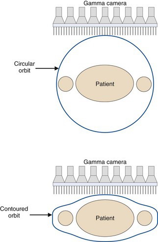
Many SPECT systems have more sophisticated gantries that allow the detector heads to trace out elliptical rather than circular orbits. Some even allow orbits that follow the contours of the patient. The body contour can be determined by an initial scout scan that, for example, uses an infrared light source and camera to trace the outline of the patient and the bed as a function of angle. The importance of this feature is evident from Figure 14-16, which shows the rapid degradation in spatial resolution with increasing distance of the object from the collimator. As shown in Figure 17-1, elliptical orbits or orbits that follow the contours of the patient allow the detector to pass closer to the patient than would be the case with circular orbits, which can lead to significant improvements in spatial resolution.
2 SPECT Systems for Brain Imaging
The University of Michigan SPRINT II system1 employs 11 γ-ray detectors in a polygonal arrangement, each detector consisting of 44 thin bars of sodium iodide [NaI(Tl)] scintillator (dimensions 3-mm-wide × 13-mm-deep × 15-cm-long) coupled to an array of twenty 38-mm-diameter photomultiplier (PM) tubes arranged behind the NaI(Tl) bars in a close-packed hexagonal array. In-slice collimation is achieved using a lead aperture ring, with 12 equally spaced 2.4-mm-wide slits, that rotates in front of the stationary detector array (Fig. 17-2A). Axial collimation is achieved using a set of stacked stationary lead foils. As the collimator ring rotates through one slit interval (30 degrees), the system acquires a complete set of fan-beam projection data.
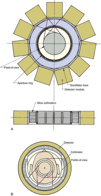
FIGURE 17-2 Cross-sectional views showing the design of two SPECT systems designed for brain imaging. A, The SPRINT system developed at the University of Michigan. This system employs a rotating collimator with 12 axial slits. Transverse and axial views are shown. B, The CERASPECT system developed by Digital Scintigraphics, Inc., Cambridge, MA. In this system, each collimator segment has a different field-of-view diameter.
(A, From Rogers WL, Clinthorne NH, Shao L, et al: SPRINT II: A second-generation single-photon ring tomograph. IEEE Trans Med Imag 7:291-297, 1988; B, From Genna S, Smith AP: The development of ASPECT, an annular single-crystal brain camera for high-efficiency SPECT. IEEE Trans Nucl Sci 35: 654-658, 1988.)
A system based on similar principles is the CERASPECT system.2 In this case, the detector is a single annular NaI(Tl) crystal (31 cm inner diameter × 8 mm thick × 13 cm wide) coupled to 63 5-cm diameter PM tubes via glass light guides (Fig. 17-2B). A parallel-hole collimator with six segments rotates in front of the detector, simultaneously providing six angular views. Each collimator segment has a different FOV. This gives a higher weighting to activity at the center of the object (which is viewed by all six collimator segments) in comparison to activity toward the periphery of the object (which is seen by a smaller number of collimator segments). This nonuniform weighting helps compensate for the effects of photon attenuation (see Sections B.1 and B.2) and provides more uniform signal-to-noise ratio across the image.
Both of these systems were designed primarily for brain imaging applications, and both provide better image resolution than a conventional SPECT system by placing the collimated detector relatively close to the head. The reconstructed spatial resolution is approximately 8 mm at the center of the brain, improving to approximately 5 mm at the edge of the brain. By comparison, a typical single-head SPECT system operated with a radius of rotation of 12.5 cm (appropriate for brain imaging) would have a resolution of approximately 12.5 mm full width at half maximum (FWHM) at the center of the brain (see Fig. 14-16). These systems also have roughly twofold to threefold higher sensitivity than a single-headed gamma camera with a general-purpose parallel-hole collimator, because multiple sets of projection data can be acquired simultaneously. This enables higher resolution to be achieved without injecting more radioactivity or lengthening the imaging time.
3 SPECT Systems for Cardiac Imaging
Figure 17-3A shows a triple-headed SPECT system designed for cardiac applications.3 Note the much smaller size of the detector heads compared with general-purpose SPECT systems. The detector heads use pixelated cesium iodide [CsI(Tl)] scintillator crystals, read out by avalanche photodiodes (Chapter 7, Section C.3). The size of each CsI(Tl) pixel is 6 mm, and there are 768 pixels in each detector head, providing a detector FOV of approximately 16 cm × 20 cm. In this system the detectors are fixed and the patient chair rotates to provide the necessary angular sampling for tomographic reconstruction. The distance between the detectors and the chair can be adjusted to accommodate patients of different size. With a low-energy, high-resolution (LEHR) collimator (see Table 14-1), the reported spatial resolution of the SPECT images is 11 mm (for a 20-cm detector-object separation) and the sensitivity for each detector head is ~72 cps/MBq (160 cpm/µCi). Because of the vertical orientation of the patient, the entire system can fit in a room as small as 2.4 m × 2.4 m.
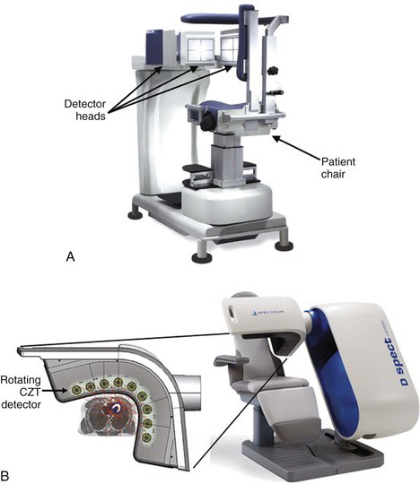
Another type of cardiac SPECT system replaces standard scintillation Anger camera designs with detector heads made up of pixels of the dense semiconductor cadmium zinc telluride (CZT) (Chapter 7, Section B).4 This system contains 10 small detector heads, distributed in an arc over the chest of the patient (Fig. 17-3B). Each detector head [2-mm CZT pixels tiled on a 40-mm (transaxial) by 160-mm (axial) area] is equipped with a parallel-hole collimator and can rotate independently to sample different projection angles, enabling a complete projection dataset to be acquired for tomographic reconstruction. The patient chair is stationary. The reconstructed spatial resolution is quite dependent on the location in the FOV, and is nonisotropic, ranging between approximately 8 and 14 mm. The sensitivity of the system is on the order of ~400 cps/MBq (900 cpm / µCi) for each detector head. The high sensitivity derives from the use of a shorter collimator with larger holes compared with the LEHR collimator.
A third design employs principles similar to the brain system shown in Figure 17-2A and described in Section 2. A multislit collimator rotates in front of an arc-shaped gamma camera that employs traditional continuous NaI(Tl) crystals read out by PM tubes.5 This rotating collimator gives rise to the different projection angles, with slice collimation provided by a stationary stack of thin concentric lead rings. For a source-to-aperture distance of 20 cm, this system can provide reconstructed spatial resolution in the range of 6 to 7 mm.
4 SPECT Systems for Small-Animal Imaging
The challenge is the small size of the organs (a few millimeters in diameter) in commonly used experimental animals such as mice and rats, relative to the spatial resolution typically obtained with SPECT systems. However, two key factors can be exploited to obtain much higher spatial resolution with SPECT in small animals compared with what can be achieved in human imaging. The first is the small volume of tissue to be imaged, which, depending on the detector size used, can permit high magnification of the object onto the detector with pinhole or converging hole collimators (see Fig. 13-7). The second related factor is that the organ of interest can always be positioned within a few millimeters (rather than many centimeters in humans) of the collimator. Because of the strong dependence of spatial resolution on source-to-collimator distance (see Fig. 14-16), much higher resolution can therefore be obtained. Furthermore, if pinhole collimation is used, the sensitivity also increases rapidly as objects of interest are moved close to the pinhole aperture (see Fig. 14-21B and Equation 14-16).
Thus the most common approach to small-animal imaging with SPECT has been to use pinhole collimation, with some magnification. Indeed, standard clinical SPECT systems have been used to great effect in small-animal imaging using a pinhole or multipinhole collimator. However, to achieve optimal resolution and sensitivity performance, in a compact device suited to a laboratory environment, dedicated small-animal SPECT systems have been developed. Although there are many different designs, these systems commonly consist of a series of compact detector heads, with interchangeable pinhole collimators that have apertures ranging from approximately 0.3 mm to 2 mm in diameter, allowing the operator to trade off between improved spatial resolution (smaller pinholes) or improved sensitivity (larger pinholes) (see Equations 14-15 and 14-16). The detector heads often use pixelated NaI(Tl) or CsI(Tl) scintillator arrays (similar to those shown in Fig. 13-15B) or arrays of CZT semiconductor elements to achieve high intrinsic spatial resolution. The simplest systems consist of two opposing detector heads, each with a single pinhole collimator, that rotate around the animal and translate along the animal to produce the angular projections required for reconstruction tomography.
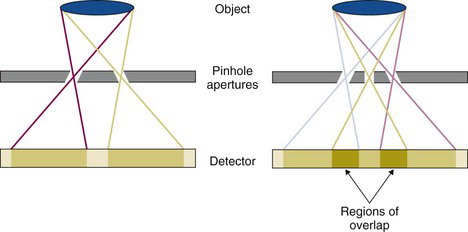
More advanced systems employ collimators with multiple pinholes to improve sensitivity. Such collimators also can increase the FOV along the axial direction without the need to translate the animal. In the most straightforward implementation, the pinholes are arranged with sufficient distance between them such that the image of the animal projected through adjacent pinholes does not overlap on the detector (Fig. 17-4, left). In some systems, the projections are allowed to overlap to a certain degree, which enables more pinholes to be used for a given detector area and magnification (Fig. 17-4, right). However, this leads to ambiguity in the projection data in the region of overlap, and tomographic reconstruction into SPECT images must use algorithms that properly model this ambiguity.
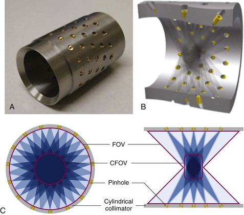
Some multipinhole animal SPECT systems are completely stationary and designed such that they simultaneously acquire sufficient angular data for tomographic reconstruction with no moving parts. This type of system is particularly suited for rapid dynamic studies, often of interest when evaluating the biodistribution of a novel radiotracer in the first seconds and minutes after injection. These systems consist of an annular collimator sleeve containing many pinholes each projecting a different angular view of the radionuclide distribution onto a detector that sits behind the collimator. Figure 17-5 shows one such collimator and a drawing showing how the pinholes are angled to cover a large FOV without the need for any movement.
Using these approaches, small-animal SPECT systems routinely reach a resolution in the range of 1 mm, and in some instances are able to produce images with a reconstructed resolution much smaller than 1 mm. Sensitivity can be high as well, because of the large number of pinholes used. Numbers are commonly in the 0.5 to 2 × 10³ cps/MBq (~1000-4000 cpm/ µCi) range, but depend strongly on the number and diameter of the pinhole apertures used, and the source-to-pinhole distance. For systems in which the projections overlap, the measured sensitivity must be interpreted with caution, as the information content of an event detected in a region of overlap is not as high as for an event in a system in which the projections do not overlap. Almost all small-animal systems use some form of iterative reconstruction algorithm with detailed modeling of the collimator apertures for reconstructing images at the highest possible resolution. Figures 17-6A and B show photographs of two SPECT systems designed for small-animal imaging applications. A useful review of small-animal SPECT systems is given in reference 6.
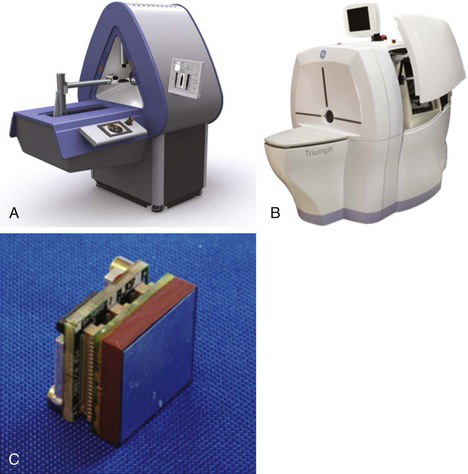
FIGURE 17-6 Photographs of two small-animal SPECT systems: A, This stationary system uses the cylindrical multipinhole collimator shown in Figure 17-5, and views are projected onto three large-area Anger cameras with no overlap between projections. With no need to move the detectors, fast dynamic studies can be performed. B, This system employs four 12.7 cm × 12.7 cm pixelated cadmium zinc telluride (CZT) detector heads and multipinhole collimators. Some rotation of the detectors is necessary to obtain all projection angles. The use of CZT provides excellent energy resolution. C, Photograph of one detector module from the system shown in B. The detector measures 2.54 cm × 2.54 cm and has a 16 × 16 array of CZT elements on a 1.59-mm pitch. The CZT thickness is 5 mm. Twenty-five of these modules are tiled together to form a 12.7 cm × 12.7 cm detector head.
(A, Courtesy MILabs, Utrecht, The Netherlands; B, Copyright Gamma Medica, Northridge, CA and GE Healthcare, Waukesha, WI; used with permission of GE Healthcare; C, Copyright Gamma Medica, Northridge, CA.)
B Practical Implementation of SPECT
Ideally, the signal level for a voxel in a SPECT image is linearly proportional to the amount of activity contained within the volume of tissue in the patient that corresponded to the location of that voxel. This would be useful not only for quantitative applications, such as perfusion studies, but also for visual interpretations of the image. In practice, this ideal result is not achieved because the realities of data acquisition do not match the idealized assumptions made for the development of reconstruction algorithms. As shown in Figure 16-1, it was assumed that the line of response (or a projection element) for a single hole in a parallel-hole collimator is an extended cylinder, but the actual response resembles a diverging cone. It was further assumed that the signal recorded was proportional to the total activity within the line of response, but in fact the signal from activity closest to the detector is more heavily weighted than from deeper-lying activity, because of attenuation by overlying tissues. Finally, it was assumed that activity outside the line of response did not contribute to the signal for the projection element, whereas there may be crosstalk between elements resulting from scattered radiation or septal penetration through the collimator. To further complicate matters, most of the discrepancies vary with the energy of the γ rays involved.
Some of the discrepancies between the idealized assumptions and the actual situation in SPECT are illustrated in Figure 17-7. The discrepancies distort the desired linear relationship between signal level and amount of activity present. They also can lead to artifacts and seriously degraded image quality. To avoid this, one must use somewhat modified approaches to data acquisition or apply postprocessing of the acquired data. This is always the case when backprojection algorithms are used, because they are rigorously grounded in the idealized assumptions noted earlier. Some of the discrepancies can be accounted for with iterative algorithms, such as the maximum likelihood-expectation maximization algorithm (see Chapter 16, Section D.2), which can incorporate these factors in its probability matrix. In this section, we describe some general approaches that are valid and potentially useful for all reconstruction algorithms.
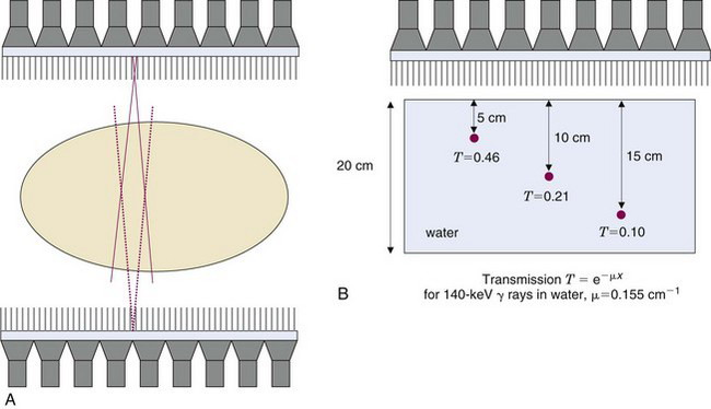
1 Attenuation Effects and Conjugate Counting
The attenuation of γ rays in SPECT imaging depends on the distance the γ rays have to travel through the tissue to reach the detector. Figure 17-7B illustrates the depth-dependent nature of this attenuation for point sources located at different positions within the body. The transmission factor for a source at a certain depth can be calculated using Equation 6-22. For 140-keV γ rays, the linear attenuation coefficient of tissue is 0.155 cm-1; therefore γ rays that are emitted from a depth of 10 cm in the body would only have a probability of 0.21 (e−10 × 0.155) of emerging from the body in their original direction. The attenuation of γ rays is even more severe in parts of the body containing significant amounts of bone, because the linear attenuation coefficient of bone is ~0.25 cm−1 at 140 keV.
One approach to reducing both the divergence of the response profile (Fig. 17-7A) and the effects of tissue attenuation (Fig. 17-7B) is conjugate counting. Conjugate counting refers to acquiring data (or image profiles) for directly opposing views and then combining these data into a single dataset or line of response. A source that is located relatively close to the detector from one view will be relatively far away in the opposing view. Hence, the response profile will be narrower and attenuation by overlying tissues will be smaller in the first view and larger in the second, with partially offsetting effects.
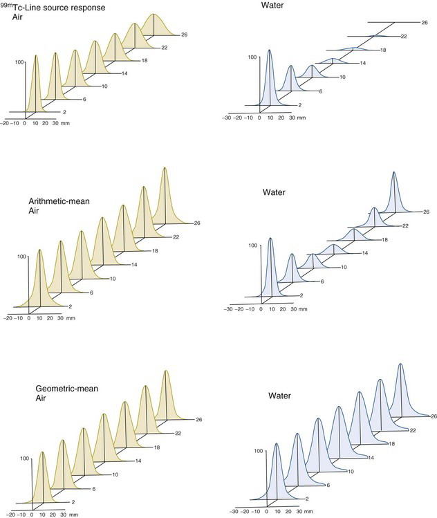
An alternative is the geometric mean, given by
Figure 17-8 shows response profiles versus source depth for a 99mTc line source for a single-view projection and for projections created from the arithmetic and geometric means of opposing views. The profiles across the top are for a single view with the source in air and for the same view with the source in water. The profile for the source in air illustrates the degradation of spatial resolution with distance from the collimator that is characteristic for a parallel-hole collimator (see also Figs. 14-18 and 14-19). The profile for the source in water shows similar degradation of spatial resolution with increasing distance but, in addition, shows decreasing amplitude of response owing to attenuation of photons by the overlying thickness of water.

Stay updated, free articles. Join our Telegram channel

Full access? Get Clinical Tree


