chapter 13 The Gamma Camera
Basic Principles
Radionuclide imaging is the most important application of radioactivity in nuclear medicine. Radionuclide imaging laboratories are found in almost every hospital, performing hundreds and even thousands of imaging procedures per month in larger institutions.
In this chapter, we discuss briefly some general aspects of radionuclide imaging, and we describe the basic principles of the most widely used imaging device, the gamma camera, also known as the Anger scintillation camera, named after its inventor, Hal Anger (see Chapter 1, Section C and Fig. 1-3). The performance characteristics of this instrument are discussed in Chapter 14. The use of the gamma camera for tomographic imaging is described in Chapter 17.
A General Concepts of Radionuclide Imaging
The purpose of radionuclide imaging is to obtain a picture of the distribution of a radioactively labeled substance within the body after it has been administered (e.g., by intravenous injection) to a patient. This is accomplished by recording the emissions from the radioactivity with external radiation detectors placed at different locations outside the patient. The preferred emissions for this application are γ rays in the approximate energy range of 80 to 500 keV (or annihilation photons, 511 keV). Gamma rays of these energies are sufficiently penetrating in body tissues to be detected from deep-lying organs, can be stopped efficiently by dense scintillators, and are shielded adequately with reasonable thicknesses of lead (see Fig. 6-17—soft tissue has attenuation properties similar to water). Alpha particles and electrons (β particles, Auger and conversion electrons) are of little use for imaging because they cannot penetrate more than a few millimeters of tissue. Therefore they cannot escape from within the body and reach an external radiation detector, except from very superficial tissues. Bremsstrahlung (see Fig. 6-1) generated by electron emissions is more penetrating, but the intensity of this radiation generally is very weak.
Imaging system detectors must therefore have good detection efficiency for γ rays. It is also desirable that they have energy discrimination capability, so that γ rays that have lost positional information by Compton scattering within the body can be rejected based on their reduced energy (see Chapter 6, Section C.3). A sodium iodide [NaI(Tl)] scintillation detector (see Chapter 7, Section C) provides both of these features at a reasonable cost; for this reason it is currently the detector of choice for radionuclides with γ-ray emissions in the range of 80-300 keV.
A significant advance occurred in the early 1950s with the introduction of the rectilinear scanner by Benedict Cassen (see Fig. 1-2). With this instrument, the detector was scanned mechanically in a raster-like pattern over the area of interest. The image was a pattern of dots imprinted on a sheet of paper by a mechanical printer that followed the scanning motion of the detector, printing the dots as the γ rays were detected.
The principal disadvantage of the rectilinear scanner was its long imaging time (typically many minutes) because the image was formed by sequential measurements at many individual points within the imaged area. The first gamma-ray “camera” capable of recording at all points in the image at one time was described by Hal Anger in 1953. He used a pinhole aperture in a sheet of lead to project a γ-ray image of the radionuclide distribution onto a radiation detector composed of a NaI(Tl) screen and a sheet of x-ray film. The film was exposed by the scintillation light flashes generated by the γ rays in the NaI(Tl) screen. Unfortunately, this detection system (especially the film component) was so inefficient that hour-long exposures and therapeutic levels of administered radioactivity were needed to obtain satisfactory images.
In the late 1950s, Anger replaced the film-screen combination with a single, large-area, NaI(Tl) crystal and a photomultiplier (PM) tube assembly to greatly increase the detection efficiency of his “camera” concept. This instrument, the Anger scintillation camera,1 or gamma camera, has been substantially refined and improved since that time. Although other ideas for nuclear-imaging instruments have come along since then, none, with the exception of modern positron emission tomography systems (see Chapter 18), has matched the gamma camera for a balance of image quality, detection efficiency, and ease of use in a hospital environment. The gamma camera has thus become the most widely used nuclear-imaging instrument for clinical applications.
B Basic Principles of the Gamma Camera
1 System Components
Figure 13-1 illustrates the basic principles of image formation with the gamma camera. The major components are a collimator, a large-area NaI(Tl) scintillation crystal, a light guide, and an array of PM tubes. Two features that differ from the conventional NaI(Tl) counting detectors described in Chapter 12 are crucial to image formation. The first is that an imaging collimator is used to define the direction of the detected γ rays. The collimator most commonly consists of a lead plate containing a large number of holes. By controlling which γ rays are accepted, the collimator forms a projected image of the γ-ray distribution on the surface of the NaI(Tl) crystal (see Section B.3). The second is that the NaI(Tl) crystal is viewed by an array of PM tubes, rather than a single PM tube. Signals from the PM tubes are fed to electronic or digital position logic circuits, which determine the X-Y location of each scintillation event, as it occurs, by using the weighted average of the PM tube signals (see Section B.2).
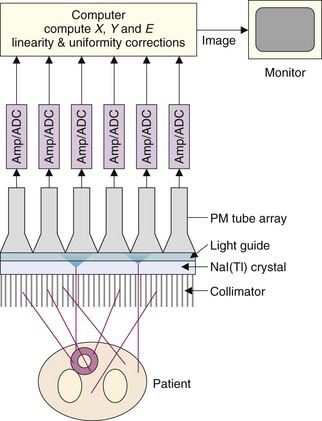
Individual events also are analyzed for energy, E, by summing the signals from all PM tubes. When the pulse amplitude of an event falls within the selected energy window, it is accepted and the X and Y values are binned into a discrete two-dimensional array of image elements, or pixels. An image is formed from a histogram of the number of events at each possible X-Y location. Large numbers of events are required to form an interpretable image because each pixel must have a sufficient number of counts to achieve an acceptable signal-to-noise level. Because images often are formed in 64- × 64-pixel or 128- × 128-pixel arrays, the counting requirements are some 103 to 104 times higher than for a simple counting detector.
Images are displayed on a computer monitor, where image brightness and contrast may be manipulated and different color tables may be employed. More sophisticated digital image processing is discussed in Chapter 20.
2 Detector System and Electronics
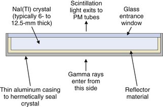
The gamma camera employs a single, large-area, rectangular NaI(Tl) detector crystal, usually 6- to 12.5-mm thick with sizes of up to 60 × 40 cm. Round crystals of 25 to 50 cm in diameter were used in many older systems. The NaI(Tl) crystal is surrounded by a highly reflective material such as TiO2 to maximize light output and hermetically sealed inside a thin aluminum casing to protect it from moisture. An optical glass window on the back surface of the casing permits the scintillation light to reach the PM tubes. A cross section of a typical gamma camera crystal assembly is shown in Figure 13-2. The choice of thickness of the NaI(Tl) crystal is a trade-off between its detection efficiency (which increases with increasing thickness) and, as shown in Chapter 14, Section A.1, its intrinsic spatial resolution (which deteriorates with increasing thickness). Most general-purpose gamma cameras have crystal thicknesses of approximately 9.5 mm. For lower-energy γ emitters, such as 99mTc and 201Tl, however, detection efficiency is adequate even with 6-mm-thick detector crystals.
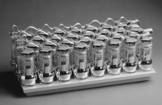
An array of PM tubes is coupled optically to the back face of the crystal with a silicone-based adhesive or grease. Round PM tubes are arranged in a hexagonal pattern to maximize the area of the NaI(Tl) crystal that is covered. Some cameras use hexagonal (or rarely, square) cross-section PM tubes for better coverage of the NaI(Tl) crystal. Typical PM tube sizes are 5 cm in diameter. Most modern cameras employ between 30 and 100 PM tubes. Figure 13-3 shows a photograph of a 30-tube model. The PM tubes are encased in a thin magnetic shield (Chapter 7, Section C.2) to prevent changes in the gain caused by changes in the orientation of the gamma camera relative to the earth’s magnetic field. The ultrasensitivity of PM tubes to magnetic fields also makes gamma cameras susceptible to the stray fields from magnetic resonance imaging systems.
Many manufacturers employ plastic light guides between the detector crystal and PM tubes, whereas others couple the PM tubes directly to the crystal. The functions of the light guide are to increase the light collection efficiency, by channeling scintillation light away from the gaps between the PM tubes, and to improve the uniformity of light collection as a function of position. The latter effect is achieved by painting or etching a carefully designed pattern onto the entrance face of the light guide. The use of the PM tubes with hexagonal or square cross-sections that can be tiled without gaps on the NaI(Tl) crystal may in some cases allow elimination of the light guide, assuming there is sufficient spreading of the scintillation light in the glass entrance window of the PM tube for accurate positioning.
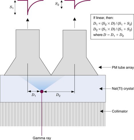
The amount of light detected by a particular PM tube is inversely related to the lateral distance between the interaction site and the center of that PM tube. This is illustrated in one dimension in Figure 13-4. Ideally, the relationship between signal amplitude and location with respect to the center of a PM tube would be linear. This would enable the position of an event to be determined by taking a weighted average or centroid of the PM tube signals using the simple relationships shown in Figure 13-4. In practice, however, the response is more complex, with a plateau directly beneath the PM tube (because the PM tube is not a “point” detector) and long, flat tails caused by reflections of light from the back and side surfaces of the NaI(Tl) crystal. Therefore a calibration for spatial nonlinearity is required (see Chapter 14, Section B).

Stay updated, free articles. Join our Telegram channel

Full access? Get Clinical Tree


