chapter 8 Electronic Instrumentation for Radiation Detection Systems
Most of the radiation detectors used in nuclear medicine are operated in a “pulse mode”; that is, they generate pulses of electrical charge or current that are counted to determine the number of radiation events detected. In addition, by analyzing the amplitude of pulses from the detector, it is possible with energy-sensitive detectors, such as scintillation and semiconductor detectors and proportional counters, to determine the energy of each radiation event detected. Selection of a narrow energy range for counting permits discrimination against events other than those of the energy of interest, such as scattered radiation and background radiation or the multiple emissions from a mixture of radionuclides.
Figure 8-1 shows in schematic form the basic electronic components of a nuclear radiation-counting instrument. These components are present in systems ranging from the most simple sample counters to complex imaging instruments. The purpose of this chapter is to describe the basic principles of these components. The electronics for specific systems also are described in Chapters 10, 12 to 14, and 18. Basic principles of electricity and electronics are reviewed in the sources cited in the Bibliography at the end of this chapter.
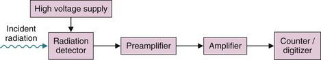
FIGURE 8-1 Schematic representation of the electronic components for a nuclear radiation counting system.
a Preamplifiers
Table 8-1 summarizes the pulse output characteristics of detectors used in nuclear medicine. Most of them produce pulse signals of relatively small amplitude. In addition, most of the detectors listed have relatively high output impedance, that is, a high internal resistance to the flow of electrical current. In handling electronic signals, it is important that the impedance levels of successive components be matched to one another, or electronic interferences that distort the pulse signals may develop and system performance will be degraded.
TABLE 8-1 TYPICAL SIGNAL OUTPUT AND PULSE DURATION OF VARIOUS RADIATION DETECTORS
| Detector | Signal (V) | Pulse Duration (µsec) |
|---|---|---|
| Sodium iodide scintillator with photomultiplier tube | 10−1-1 | 0.23* |
| Lutetium oxyorthosilicate scintillator with photomultiplier tube | 10−1-1 | 0.04* |
| Liquid scintillator with photomultiplier tube | 10−2-10−1 | 10−2* |
| Lutetium oxyorthosilicate scintillator with avalanche photodiode | 10−5-10−4 | 0.04* |
| Direct semiconductor detector | 10−4-10−3 | 10−1-1 |
| Gas proportional counter | 10−3-10−2 | 10−1-1 |
| Geiger-Müller counter | 1-10 | 50-300 |
There are two main types of preamplifier configurations used with radiation detectors: the voltage-sensitive preamplifier and the charge-sensitive preamplifier. Figure 8-2 shows a simplified diagram of these two configurations. The symbol  represents the signal (pulse)-amplifying component. The resistor (R) and capacitor (C) provide pulse shaping. The signal from the detector is typically a sharply rising pulse of electrical current of relatively short duration (
 1 µsec, except for Geiger-Müller (GM) counters; see Table 8-1). The voltage-sensitive preamp amplifies any voltage that appears at its input. Because radiation detectors are charge-producing devices, this input voltage, Vi, is given by the ratio of the charge, Q, and the intrinsic capacitance of the detector and other components in the input circuit, Ci:
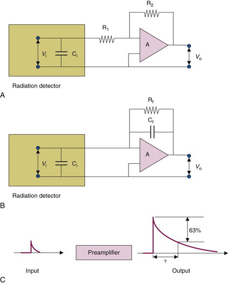
 represents a voltage or current amplifying element. C, Input and output pulse signals for a charge-sensitive preamplifier. τ = (R f × Cf) is the time constant of the pulse-shaping circuit.
in which R1 and R2 are as shown in Figure 8-2. The minus sign indicates that the polarity of the pulse has been changed.

is seen to be independent of the input capacitance, Ci.
The product R f × Cf is called the time constant τ of the pulse-shaping circuit. The voltage decreases exponentially, dropping by 63% of its initial value during one time constant interval (see Fig. 8-2C). When R f is given in ohms and Cf in farads, the time constant is given in seconds. Typical preamplifier time constants for nuclear medicine detectors (excepting those applications that require fast timing signals) are 20 to 200 µsec.
The amount of amplification provided by the amplifier element of the preamplifier varies with the type of detector. With scintillation detectors that use photomultiplier (PM) tubes, the PM tube already provides a considerable degree of amplification (106-107); thus relatively little additional amplification may be needed. Typically, a preamplifier gain factor (ratio of output to input amplitudes) of 5-20 is used for these detectors; however, some NaI(Tl):PM tube systems employ no preamplifier gain (gain factor of 1).
For the best results, the preamplifier component should be located as close as physically possible to the detector component. This maximizes the electronic signal-to-noise ratio (SNR) by amplifying the signal before additional noise or signal distortion can occur in the long cable runs that frequently separate the detector from the rest of the signal-processing components. This is particularly critical for detectors with small output signals (e.g., semiconductor detectors or scintillation detectors used for detecting low-energy radiations). It also is important for applications in which energy resolution is critical (see Chapter 10, Section B.7). Frequently, detectors and preamplifiers are packaged and sold as single units.
b Amplifiers
1 Amplification and Pulse-Shaping Functions
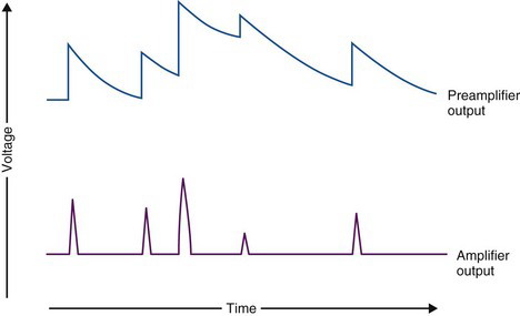
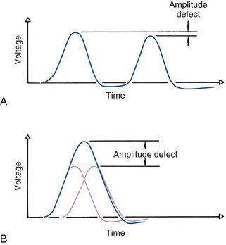
Pulse shaping—i.e., pulse shortening—is an essential function of the amplifier. The output of the preamp is a sharply rising pulse that decays with a time constant of about 50 µsec, returning to baseline after approximately 500 µsec. Thus if a second pulse occurs within 500 µsec, it rides on the tail of the previous pulse, providing incorrect amplitude information (Fig. 8-3). The system could not operate at counting rates exceeding a few hundred events per second without introducing this type of amplitude distortion.
The pulse-shaping circuits of the amplifier must provide an output of cleanly separated pulses, even though the output pulses from the preamp overlap. It must do this without distorting the information in the preamplifier signal, which is, mainly, (1) pulse amplitude (proportional to the energy of radiation event for energy-sensitive detectors) and (2) rise time (time at which the radiation event was detected). An additional function of the pulse-shaping circuits is to discriminate against electronic noise signals, such as microphonic pickup and 50- to 120-Hz power line frequency.
2 Resistor-Capacitor Shaping
Basic RC pulse-shaping circuits are shown in Figure 8-4. When a sharply rising pulse of relatively long duration (e.g., preamplifier output pulse) is applied to a capacitor-resistor (CR), or differentiation circuit (see Fig. 8-4A), the output is a rapidly rising pulse that decays with a time constant τd determined by the RC product of the circuit components (Equation 8-4). The amplitude of the output pulse depends on the amplitude of the sharply rising portion of the input pulse and is insensitive to the “tail” of any preceding pulse. Note that a CR differentiation circuit also is used for pulse shaping in the preamplifier; however, the time constants used in the preamplifier circuits are much longer than those used in the amplifier. Figure 8-4A also illustrates how the CR circuit discriminates against low-frequency noise signals.
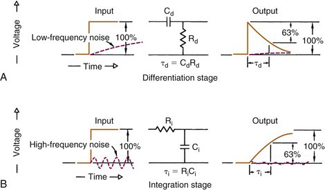
Figure 8-4B shows an RC, or integration circuit. (Note that differentiation and integration differ only by the interchanging of the resistor R and the capacitor C.) When a sharply rising pulse is applied to this circuit, the output is a pulse with a shape described by
where Vi is the amplitude of the input pulse and RC = τi is the integration time constant of the circuit. This circuit discriminates effectively against high-frequency noise, as illustrated in Figure 8-4B.
Figure 8-5A shows a pulse-shaping circuit combining differentiation and integration stages. When the time constants of the two circuits are equal (τ = τi = τd), the output is a pulse that rises to a maximum value in a time equal to 1.2τ and then decays to approximately zero in 7τ. The maximum amplitude of the output pulse is determined by the amplitude of the input pulse. For scintillation and semiconductor detectors, a time constant in the range τ ~ 0.25-5.0 µsec usually is chosen. Thus the output pulse is shortened considerably relative to the pulse from the preamplifier (50-500 µsec) and is suitable for high counting rate applications. Except for a very small negative overshoot at the end of the pulse, the output pulse from this circuit has only one polarity (positive in Fig. 8-5A) and is called a unipolar output.
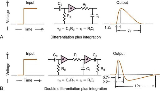
Figure 8-5B illustrates another type of shaping, called double differential shaping. The output pulse from this circuit has both positive and negative components and therefore is a bipolar pulse. For equal time-constant values, the bipolar output pulse has a shorter rise time and positive portion and a longer total duration than the unipolar output pulse. Unipolar pulses are preferred for signal-to-noise characteristics and are used where energy resolution is important. Bipolar pulses are preferred for high counting rate applications.
Research-grade amplifiers generally are provided with adjustable pulse-shaping time constants. A longer time constant provides better pulse amplitude information and is preferred in applications requiring optimal energy resolution, for example, with semiconductor detectors (Chapter 10, Section C.1). A shorter time constant is preferred in applications requiring more precise event timing and higher counting rate capabilities, such as scintillation cameras (Chapters 13 and 14) and coincidence detection of positron annihilation photons (Chapter 18).
3 Baseline Shift and Pulse Pile-Up
Baseline shift and pulse pile-up are two practical problems that occur in all amplifiers at high counting rates. Baseline shift is caused by the negative component that occurs at the end of the amplifier output pulse. A second pulse occurring during this component will be slightly depressed in amplitude (Fig. 8-6A). Inaccurate pulse amplitude and an apparent shift (decrease) in energy of the detected radiation event are the result (see Fig. 10-9).
Special circuitry has been developed to minimize baseline shift. This is called pole zero cancellation, or baseline restoration. This type of circuitry is employed in modern scintillation cameras to provide a high counting rate capability, particularly for cardiac studies. These circuits are described in the sources cited in the Bibliography at the end of this chapter.
At high counting rates, amplifier pulses can occur so close together that they fall on top of each other. This is referred to as pulse pile-up (Fig. 8-6B). When this happens, two pulses sum together and produce a single pulse with an amplitude that is not representative of either. Pulse pile-up distorts energy information and also contributes to counting losses (dead time) of the detection system, because two pulses are counted as one (Chapter 11, Section C).
Both baseline shift and pulse pile-up can be decreased by decreasing the width of the amplifier pulse (i.e., the time constant of the amplifier); however, shortening of the time constant usually produces poorer SNR and energy resolution. It is generally true that all the factors that provide high count rate capabilities in amplifiers also degrade energy resolution (Chapter 10, Section B.7).
Stay updated, free articles. Join our Telegram channel

Full access? Get Clinical Tree


