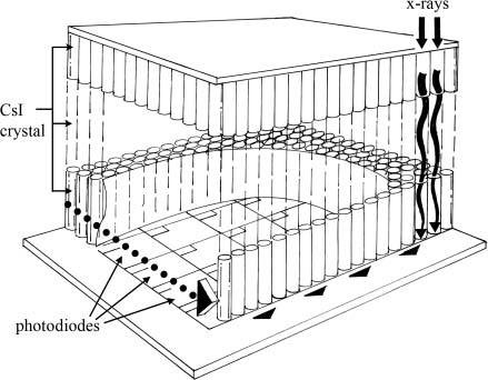
3 Digital Mammography Equipment Mammography technology may be divided into three functions: image acquisition, display, and storage. With screen-film mammography, the image acquisition process starts when the breast is exposed to x-rays. As the x-rays pass through the breast, they are absorbed and scattered within the tissues. The attenuated x-rays pass through a grid, interact with the image receptor, and form a latent image on film. The exposed film is processed by reducing the silver ions in the x-ray film emulsion to metallic silver. The film is then treated with fixer that both removes excess silver and is a preservative. Finally, the film is rinsed to remove fixer.1 The resulting film is the key medium that is used for both display and later storage. Image acquisition, display, and archiving are interlinked by screen-film mammography. For example, if the mammogram is suboptimally acquired and is too light, display of the image on a view box will be compromised. There is no screen-film display method that will correct this problem. However, with digital mammography, image acquisition, display, and archival functions involve separate systems. This separation of function is important because in screen-film mammography, any problem with one of the functions affects the quality of the entire process. However, with digital mammography, each process may be optimized independently of the other functions. This separation of function allows digital mammography to take advantage of several technical opportunities. For example, researchers have found that although 4% of digital mammograms are poorly exposed, 100% of the final mammographic displays are adequate as a result of digital postprocessing.2 There are two types of digital mammography acquisition systems: one based on digital x-ray technology and the other based on computed radiology (CR) technology. Digital x-ray systems convert x-rays directly to a digital image. The conversion occurs essentially instantaneously. CR systems expose a CR plate to x-rays and then “read” the image from the plate by scanning the plate with a laser beam. These systems also generate a digital image, but the image is generated when the plate is read and not at the time of exposure. Digital x-ray systems have the advantage of generating an image instantly after the exposure. This provides rapid feedback to the technician if the image is suboptimal, such as when the patient is poorly positioned. CR systems are typically less expensive than digital x-ray systems. There are three types of direct digital x-ray systems: (1) those with cesium iodide (CsI) phosphor detector systems, (2) those with selenium, and (3) those with quantum counting detectors. CsI phosphor systems were the first flat-plate mammographic detectors available in the United States. Thallium-activated cesium iodide [CsI (T1)] crystals were developed for digital mammographic systems because these crystals produce better resolution compared with earlier conventional x-ray phosphors. The CsI (T1) crystals form thin columns. The light produced by the crystal passes down the column to the photodiode. Compared with other phosphors, the CsI (T1) crystals reduce the lateral spread of the light and improve resolution. Like a multilayer cake, the CsI phosphor detector has three layers (Fig. 3–1). The base of this detector is coated with a layer of amorphous silicon. On top of this silicon is a layer of light-sensitive photodiodes. Each photodiode is a tiny square. These photodiodes form a matrix that microscopically looks like a quilt. Each photodiode contains a thin-film transistor switch. Finally, a layer of thallium-activated CsI (Tl) crystals are deposited on the photodiodes. The CsI flat panel works in the following manner. When an x-ray strikes a CsI (Tl) crystal, the crystal produces light. The light travels down the length of the crystal and is detected by the photodiode. The photodiode converts the light into an electrical charge. This charge is stored until the thin-film transistor switches are electronically activated. When the switches are activated, the charged photodiode produces a signal that is read out and digitized.3–8 Like a flat-panel detector, a slot scanning detector uses a CsI (Tl) phosphor. In this type of detector, the CsI (Tl) phosphor is deposited on optical fibers that are connected to charge-coupled devices (CCDs). A CCD is an electronic chip that converts light photons to an electrical charge. As in a CsI flat-panel detector, x-rays strike the CsI (Tl) phosphor and are converted into light photons. The light photons pass down the crystal to the optical fibers. The light then travels through the optical fibers to the CCDs, which convert the light into an electronic signal that is digitized. The size of the CCDs limits the size of the detector. The CCDs in a slot scanning detector are placed together like tiles on a floor; the total area of the detector is thus relatively small compared with other types of detectors. The current commercially available slot scanning detector using this method is long and narrow. Because of this, the x-ray beam is collimated in a narrow slot to match the geometry of the detector. Also, because this type of detector is too narrow to read out information from the entire breast, the detector and the x-ray beam concurrently sweep across the breast. The image acquisition time in slot scanning detectors is longer than for other devices. This system requires a powerful x-ray tube and generator, as most of the x-rays are removed by the tight collimation. However, the collimation reduces scatter, and a grid is not necessary. *President, Imorgan Medical, LLC, Menlo Park, California Figure 3–1 Schematic of a flat-panel cesium iodide (CsI) phosphor detector. The x-rays strike the CsI crystals and form light photons, which travel down the shaft of the crystal and strike a photodiode. The photodiode converts the light into an electrical charge. This charge is stored until the thin-film transistor switches (associated with each photodiode) are electronically activated. When the switches are activated, the charged photodiode produces a signal, which is read out and digitized. Selenium flat-panel detectors differ from CsI detectors in that the x-rays are directly converted into an electrical signal. This type of detector has three layers: an amorphous silicon base, an electrode pad central layer, and an amorphous selenium top layer. When x-rays hit the amorphous selenium, the selenium produces an electric charge by forming electron-hole pairs. An electric field is then applied between the electrodes, causing the electron-hole pairs to move to the polarized electrode. The charge created by these electron-hole pairs is read out on electrode pads that are laid on a plate of amorphous silicon. Because this system is not dependent on light photons, it is not subject to loss of resolution from divergence of light. Furthermore, the resolution of this method is not affected by the thickness of the photoconductor. The third type of direct digital x-ray system is the quantum counting detector. This type counts each captured x-ray and converts them into signals. The process is fundamentally different from that employed in light phosphor detectors, which absorb x-rays and then produce an electric charge. The charge is proportional not only to the number of x-rays but also to the energy of the x-rays because more light is created by higher energy x-rays. If you wish to count all x-rays as equal, then you would need to count x-ray quanta. An example of a quantum counting detector is one that uses silicon crystals to receive x-rays. The charge is collected and then transformed into an electrical pulse. In another system, the captured x-rays convert a high-pressure gas to ions, and the ions form an electrical signal.5 CR mammographic acquisition systems are similar to those used for nonmammographic applications. X-rays that have passed through the breast temporarily free the electrons in the phosphor screen from the crystal matrix. These freed electrons are captured and stored in traps within the crystal lattice. The number of filled traps is proportional to the amount of absorbed x-rays. After the screen is exposed to x-rays, the technologist then places this phosphor screen in a reader. Within the reader, the screen is scanned by a red laser light, which liberates the electrons from the traps. The electrons then return to their original resting state (Fig. 3–2
 Digital Acquisition
![]()
Stay updated, free articles. Join our Telegram channel

Full access? Get Clinical Tree


