Dose Considerations in CT Perfusion
Lifeng Yu
Shuai Leng
Lance J. Phillips
Dawn Banghart
Cynthia H. McCollough
Introduction
Computed tomography (CT) perfusion has received increased attention in various oncology and nononcology applications owing to its ability to provide quantitative information on tissue or tumor vascularity.1,2,3 Use of CT perfusion to distinguish between reversible and irreversible cerebral ischemia for acute stroke patients has been well established.3,4,5 CT perfusion has also found important applications in diagnosis, staging, grading, and monitoring treatment response for various cancers.2 Despite its great potential, one of the major obstacles for integrating CT perfusion into routine clinical practice is the concern over radiation dose.
CT perfusion involves repeated scans over the same anatomy to obtain time-attenuation curves (TACs) in the tissue of interest, based on which perfusion parameters such as blood flow, blood volume, and vascular permeability can be estimated.6,7,8,9 Typical acquisition times are 40 to 60 seconds for brain perfusion,10 30 seconds for myocardial perfusion,11 180 seconds for renal perfusion,12 135 seconds for liver perfusion,13 and 125 seconds for lung perfusion.14 With the advent of multislice CT technology and the increase of longitudinal coverage, “whole organ” or “multiorgan” perfusion imaging has become feasible.15,16 The widest coverage without table motion is currently 16 cm with a 320-detector-row scanner. on scanners with fewer detector rows, to further increase the longitudinal coverage, a so-called shuttle or toggle mode was introduced, in which the table is moved back and forth during the scan.17,18 A longitudinal coverage up to 28.4 cm in 2.5 seconds can be achieved with a detector collimation of 3.84 cm.
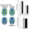
Because of the longer scan duration, radiation dose in perfusion studies is usually much higher than in a routine CT scan. For example, in a properly performed CT brain perfusion exam,10 the radiation output is typically 4 to 10 times of that in a routine head CT exam (200 to 500 mGy vs. 50 to 70 mGy, in terms of volume CT dose index [CTDIvol] measured on a standard cylindrical phantom with a diameter of 16 cm). The peak skin dose is typically 80 to 350 mGy, which is much higher than that received in a routine head CT exam.19 CTDIvol and skin dose are defined in detail in the next section. In addition, multiple perfusion exams may be necessary to monitor the response to treatment, which further increases the applied radiation dose.
Inappropriately high dose settings (e.g., using routine head dose in each single head perfusion scan) were used in the past owing to the lack of understanding on the image quality and radiation dose requirement on perfusion exams, resulting in skin reddening and/or hair loss in some cases.20 Tremendous efforts have been spent to educate CT users regarding appropriate radiation dose settings in CT perfusion to avoid such deterministic injuries. For appropriately performed CT perfusion exams, the skin dose is much lower than the threshold dose for deterministic effects to occur. It is still prudent, however, to use radiation doses that are as low as reasonably achievable, consistent with obtaining sufficient image quality to complete the diagnostic task.
This chapter will describe various dose considerations in CT perfusion, including how to quantify radiation dose in CT perfusion, how to optimize scanning techniques to reduce radiation dose, and how to evaluate the risk and benefit of CT perfusion exams.
Quantifying Radiation Dose in CT Perfusion
A basic quantity to quantify radiation dose is absorbed dose, which is defined as the energy deposited by ionizing radiation per unit mass of material.21 The SI unit of absorbed dose is gray (Gy, 1 Gy = 1 J/kg). In diagnostic CT, milligray (mGy) is typically used. Because the dose distribution on a given patient in a CT scan is inhomogeneous, the dose in a patient is more accurately quantified on each organ in terms of organ dose, which is the average absorbed dose in each organ. Skin dose is the organ dose in the skin area.
Because of the varying size, shape, and tissue composition of patients, organ dose or patient dose is not convenient to specify scanning parameters and radiation output of the scanner. Several dedicated dose descriptors have been developed in CT to accommodate its specific data acquisition geometry. The most commonly used dose descriptors in CT include CT dose index (CTDI) (and its variations) and dose length product (DLP).22,23
CTDI is defined as the integral of dose profile D(z) (one-dimensional dose distribution along the longitudinal axis) in a single axial scan, normalized to the nominal x-ray beam width:
where N is the number of data acquisition channels and T is the channel width.24 CTDI was proposed to represent the multiple scan average dose (MSAD) in the central image of a scan range by performing a single scan
instead of multiple scans, which substantially shortened the data acquisition time in the early days. In practice, CTDI is usually measured in an axial scan using a 100-mm pencil ion chamber, which is defined as CTDI100.22 Alternative dosimeters and measurement methods have been recently investigated.25,26 Two standardized cylindrical phantoms are used in CTDI measurements, 16-cm diameter for the head and 32-cm diameter for the body. Owing to the attenuation of the x-ray beam and the rotational data acquisition geometry in CT, CTDI measurements are conducted at both peripheral and central locations. Peripheral CTDI is approximately twice of the central CTDI measured in the body CTDI phantom, and is very similar in the head phantom.23 A weighted summation of peripheral and central CTDI values is defined as CTDIw. For a helical or axial scan, overlaps or gaps in consecutive radiation beams might exist, which affect both the total dose and dose distribution. To take this into account, volume CTDI (CTDIvol) was introduced:
instead of multiple scans, which substantially shortened the data acquisition time in the early days. In practice, CTDI is usually measured in an axial scan using a 100-mm pencil ion chamber, which is defined as CTDI100.22 Alternative dosimeters and measurement methods have been recently investigated.25,26 Two standardized cylindrical phantoms are used in CTDI measurements, 16-cm diameter for the head and 32-cm diameter for the body. Owing to the attenuation of the x-ray beam and the rotational data acquisition geometry in CT, CTDI measurements are conducted at both peripheral and central locations. Peripheral CTDI is approximately twice of the central CTDI measured in the body CTDI phantom, and is very similar in the head phantom.23 A weighted summation of peripheral and central CTDI values is defined as CTDIw. For a helical or axial scan, overlaps or gaps in consecutive radiation beams might exist, which affect both the total dose and dose distribution. To take this into account, volume CTDI (CTDIvol) was introduced:
where I is the table translation per rotation.22 The unit mGy is commonly used in CT. The value of CTDIvol is required to be displayed prospectively on the CT console before each patient scan.27 Typical CTDIvol values of brain perfusion and body perfusion CT for selected scanning protocols are listed in Tables 3.1 and 3.2, respectively. In body perfusion CT, 100 kV or 80 kV is typically used instead of 120 kV to increase the iodine contrast.27 Here, the increased iodine contrast is a combined effect of K-edge, photon–electric interaction, Compton interaction, and the different attenuation properties between iodine and background materials. The tube current is adjusted according to body thickness. Besides tube potential and tube current settings, CTDIvol is also highly related to total scan time and the temporal sampling rate, which can vary among protocols. In general, CTDIvol ranges from 100 to 300 mGy for body perfusion CT.
TABLE 3.1 RADIATION DOSE (CTDIVOL) FOR SELECTED BRAIN PERFUSION PROTOCOLSa | |||||||||||||||||||||||||||||||||||
|---|---|---|---|---|---|---|---|---|---|---|---|---|---|---|---|---|---|---|---|---|---|---|---|---|---|---|---|---|---|---|---|---|---|---|---|
| |||||||||||||||||||||||||||||||||||
Although CTDIvol can approximate MSAD at the central location of the scan volume of a standard phantom, it doesn’t indicate the total energy delivered during the whole scan. Two scans with the same CTDIvol can deliver very different amounts of total energy. To address this, DLP was introduced, which is defined as the multiplication of CTDIvol and scan length, with a commonly used unit of mGy·cm.22,28
TABLE 3.2 RADIATION DOSE (CTDIVOL) FOR SELECTED BODY PERFUSION PROTOCOLS | ||||||||||||||||||||||||||||||||||||||||||||||||
|---|---|---|---|---|---|---|---|---|---|---|---|---|---|---|---|---|---|---|---|---|---|---|---|---|---|---|---|---|---|---|---|---|---|---|---|---|---|---|---|---|---|---|---|---|---|---|---|---|
| ||||||||||||||||||||||||||||||||||||||||||||||||
Another frequently used dose descriptor is effective dose, which takes into account the different sensitivity of tissues/organs to radiation.22,29,30,31 The effective dose from a nonuniform radiation exposure reflects the risk in terms of a whole-body irradiation. It can be used to compare different imaging techniques (e.g., radiography and CT). The SI unit for effective dose is the mSv. Effective dose can be calculated from organ dose and tissue weighting factors published by the International Commission on
Radiological Protection (ICRP).29,30 Effective dose can also be roughly estimated from DLP by using a conversion factor (k factor) specified to scanned body parts and patient age.32,33 These conversion factors, however, assume the irradiation of an entire region (e.g., head or thorax) and are not applicable for scans that irradiate only a subset of a scan region. In addition, it should be noted that effective dose is intended to be used as a relative measure of risk from radiation detriment for a population, but not to describe the dose to an individual. A more accurate approach for patient dose estimate is to calculate all pertinent organ doses for each individual patient.
Radiological Protection (ICRP).29,30 Effective dose can also be roughly estimated from DLP by using a conversion factor (k factor) specified to scanned body parts and patient age.32,33 These conversion factors, however, assume the irradiation of an entire region (e.g., head or thorax) and are not applicable for scans that irradiate only a subset of a scan region. In addition, it should be noted that effective dose is intended to be used as a relative measure of risk from radiation detriment for a population, but not to describe the dose to an individual. A more accurate approach for patient dose estimate is to calculate all pertinent organ doses for each individual patient.
CTDI and its variations are good indicators of scanner radiation output and have been widely used in routine quality control and protocol optimization. CTDI (or CTDIvol), however, is not patient dose.34 By definition, CTDIvol approximately represents the weighted average dose delivered to a uniform cylindrical phantom at a given size (either 16- or 32-cm diameter), which doesn’t represent any patient owing to the differences in size, body shape, and attenuation. Different approaches have been investigated to estimate organ dose to the patient during perfusion scans, including direct measurements on phantoms, Monte Carlo simulation, and conversion factor–based estimation.
Direct dose measurements in perfusion CT can be performed using thermoluminescent dosimeters (TLDs) and anthropomorphic phantoms.35,36,37 Multiple TLD rods and chips are placed at multiple locations of the phantom and a dose map can be generated by reading out from each TLD. Average organ dose and dose distributions can be obtained. Skin dose is of particular interest in perfusion CT because skin injury (deterministic effect) is possible if incorrect scan setup is used.20,38 Besides TLD, other point dosimeters, such as optically stimulated luminescence (OSL), can also be used in perfusion dose measurement.25,39,40 Radiochromic film is another option for assessing skin dose. In general, direct dose measurements are limited to phantoms. Although anthropomorphic phantoms can be used, dose values still need to be interpreted with caution because of the difference of size, body shape, and attenuation between patients and phantoms. In general, direct dose measurement on patients is not practical, except for maybe certain skin dose measurements.
Monte Carlo simulation, a method simulating a large number of photon transports through an object, has been used to calculate the dose deposited in both medical imaging and radiation therapy.41,42 General purpose Monte Carlo code has been modified to specifically estimate radiation dose in axial and spiral CT scans, and Monte Carlo–based CT dose simulation packages have been developed.42,43 For accurate dose estimation, scanner geometry, x-ray source, bow-tie filter, beam collimation, and other scanner-related factors have to be accurately modeled. Phantoms, generic patient models, and patient-specific models from CT images have been used as the virtual objects in Monte Carlo simulations for CT dose estimation. This method has the flexibility to simulate different scanning parameters to investigate their influence on patient dose without repeated patient scans.19 Organ dose and dose distributions can be obtained using Monte Carlo simulation. This method can also provide patient-specific dose estimation using a patient’s own CT images.44 Effort is needed, however, for patient model definition from CT images, including organ segmentation, and it can take a long time to perform the dose calculation. Further work is needed to deploy this method in routine clinical practice with a short turnaround time.
Related posts:
 Clinical Applications and Theoretical Principles: Primer on Physics of MR and Hardware
 Flow Territory Mapping: Region-Selective Arterial Spin Labeling
 Cerebrovascular Anatomy and Regional Blood Supply
 Tumor Vasculature: Structure and Function
 Gastrointestinal Imaging
 Cerebral Perfusion Studies in Substance Abuse and Dependence
Stay updated, free articles. Join our Telegram channel

Full access? Get Clinical Tree


