Flow Territory Mapping: Region-Selective Arterial Spin Labeling
Matthias J.P. van Osch
Matthias Günther
Eric C. Wong
Background
Region-selective arterial spin labeling (rsASL) aims at determining what tissue is fed by a particular artery and is also known under the names of region-specific ASL, flow territory mapping ASL, and (super)selective ASL. The technique mimics the information obtained from intra-arterial digital subtraction angiography (iaDSA) in which, under X-ray monitoring, a contrast agent is injected into an artery to image the downstream vasculature. iaDSA provides only information of the vascular tree, whereas rsASL can image either the vasculature sprouting of the targeted vessel via ASL angiography or the tissue fed by this artery by ASL perfusion imaging. Information about the layout of flow territories can be crucial for guiding vascular interventions, for determining the origin of an embolic stroke, for understanding the layout of arteriovenous malformations (AVMs), and for depicting the arterial feeding of tumors (e.g., to facilitate local drug delivery).
rsASL is especially attractive for preinterventional planning, because at the moment the interventional radiologist has little knowledge on the patient’s specific layout of the vasculature or the tissue supplied by the vessels on which the procedure will be performed. This not only makes it difficult to prepare for the intervention but also, probably more importantly, makes it hard to perform an adequate risk assessment before the patient is catheterized. rsASL can provide the physician with both a detailed depiction of the vasculature by means of (superselective) ASL angiography1,2 and information that indicates which tissue is fed by the arteries that will be operated on. Images of the brain tissue supplied by the targeted arteries are easily combined with normal anatomic magnetic resonance imaging (MRI) as well as functional MRI (fMRI) to show the exact location of eloquent brain areas, thereby providing the treating physician with a complete picture of the specifics of the patient before starting with the procedure.
The most obvious application of rsASL is to differentiate between different origins of ischemic infarction, like large-artery atherosclerosis, cardioaortic embolism, and small-artery occlusion, based on the actual layout of the arterial blood supply. This will, for example, enable one to pinpoint the suspected artery in patients with large-artery atherosclerosis, an important prerequisite for careful screening for unstable plaque. In clinical practice, population-averaged flow territory maps are used, but individual confirmation of the specific layout of the flow territories might prevent mistreatment or misclassification.3
Although less frequently seen in the radiologic clinic, the impact of rsASL on the treatment planning of AVMs can be even larger. Even on DSA it is challenging to identify whether a feeding artery of an AVM exits straight into a vein or whether brain tissue is fed first. Because treatment often consists of total occlusion of feeders, it is vital to know whether or not some tissue is still dependent on these arteries for blood supply. Finally, new treatment strategies are continuously proposed for brain tumors. Some of these treatments do profit when delivered locally, through the feeding artery. rsASL would enable one to tune the delivery volume of the administered drug, ensuring that no part of the tumor is missed or that a too high dose is delivered to normal brain tissue. For brain surgery, it can be of additional value to know which arteries are feeding the tumor, to predict, for example, the loss of blood. In summary, rsASL opens up a complete new arsenal of imaging opportunities from which the clinical benefits will have to be proven in the next years.
Two different approaches can be distinguished to enable rsASL: Labeling can be limited to a single artery and the flow territory of this artery is subsequently imaged; alternatively, the labeling efficiency can be varied in several different spatial patterns and subsequently postprocessing is employed to decode the flow territories of multiple arteries at the same time. Of course, the last approach has the advantage that information on multiple flow territories is obtained in a single scan, but the first approach provides highly selective information with little chance of artifacts influencing the interpretation, which is important especially in complicated situations where multiple arteries can feed a certain brain region. For multiple-vessel rsASL, more technical background information needs to be considered for the clinical interpretation of the images and, depending on the employed technique, can show erroneous results—for example, when arteries are running close to each other in the labeling area. Single-vessel rsASL and multivessel rsASL will be introduced in the following sections and subsequently the applications of these techniques in normal volunteers and example patient studies will be described.
Single-Vessel Region-Selective Arterial Spin Labeling
Many different approaches have been proposed to limit the labeling effectively to a single artery or at least a single part of the arterial constellation. These approaches
can be grouped as follows: Approaches taking advantage of (a) the spatial radiofrequency (RF) distribution of transmit coils, (b) spatially selective RF pulses, and (c) rotating gradients that over time restrict (pseudo-) flow-driven adiabatic inversion to a single location.
can be grouped as follows: Approaches taking advantage of (a) the spatial radiofrequency (RF) distribution of transmit coils, (b) spatially selective RF pulses, and (c) rotating gradients that over time restrict (pseudo-) flow-driven adiabatic inversion to a single location.
Restriction of Labeling from Coil Transmit Profile
The most extreme example of this approach is the use of a separate labeling coil positioned on top of an artery in the neck.4 Such a local transmit coil for labeling can subsequently be combined with a traditional setup for readout of the ASL images (i.e., a multichannel receive coil in combination with a whole-body transmit coil). Because two transmit coils are employed, the system must be able to switch the RF power between both transmit coils, whereas the other coil needs to be detuned while transmitting. By incorporating a switch into the hardware chain and by generating a trigger pulse for this switch in the software of the sequence, the RF power can be sent through either the surface coil used for labeling or the normal transmit coil for the imaging part of the ASL scan. The RF power deposition of the local labeling coil should always be estimated (e.g., based on finite difference time domain [FDTD] simulations). Talagala et al.5 showed, for example, a skin temperature increase of approximately 1.2°C during continuous labeling by their specially designed multielement local labeling coil. Because of the complicated hardware setup that is necessary for this approach, it is difficult to implement it on clinical systems and is therefore most often employed in research sites aimed at development of (ultra-high-field) ASL-MRI.
The separate labeling coil setup is most compatible with a (pseudo-)continuous ASL (CASL or pCASL) because the coverage in the z-direction is too limited for efficient labeling by means of a pulsed ASL (PASL) approach. Furthermore, when the RF of the labeling coil does not reach the brain tissue, the most simple control condition (i.e., no RF) can be used, because magnetization transfer effects from the labeling RF pulses will be negligible. This will especially hold true for very small surface coils that affect only a limited region in the neck. For CASL this will lead to an increase in the labeling efficiency compared to a nonselective CASL experiment, because the control condition of the amplitude-modulated CASL sequence leads to a 20% to 40% lower labeling efficiency.6 A surface coil will most often only affect the spins in the blood of a single artery, and therefore one will automatically limit the perfusion signal to the flow territory of this artery. This might be a disadvantage in the clinical workup when the availability of a nonselective perfusion map may be of equal importance. Measuring the flow territories of multiple arteries would, however, require a change in position of the surface coil or a more complicated setup with multiple transmit coils. Applications of separate labeling coils for rsASL have so far been limited to a few proof-of-concept studies.
When the spatial extent of the transmit coil is larger but still exhibits some spatial inhomogeneity, the use of a slice-selective labeling approach with an oblique labeling plane can help in effectively restricting the labeling to a single side of the arterial vasculature. This labeling plane is planned in such a way that the labeling plane intersects the targeted vessel in a region with sufficient RF deposition, whereas the other vessels intersect the labeling plane at locations with no or very little RF efficiency, thereby eliminating any labeling effect. A complication is that the angle between the labeling plane and the artery should still be at an approximate perpendicular orientation to achieve a reasonable labeling efficiency of the blood in a targeted artery. This approach has been employed both with a surface coil7 and with a transmit/receive head-coil.8 Especially the latter approach can be employed on clinical MR scanners, because many systems are still equipped with such a transmit/receive head-coil. Transmit/receive head-coils, however, have inferior signal-to-noise ratios (SNRs) compared to multichannel receive coils in combination with the body transmit coil and can be considered a leftover of the preparallel imaging era, although many MRI manufacturers are still delivering these, for example, for image quality assurance. Furthermore, the ability to select different arteries is rather limited, because there needs to be sufficient spatial separation between the vessels to have sufficient difference in RF delivery while keeping the angle with the targeted artery approximately perpendicular to the targeted artery. Finally, because the main drop-off in RF delivery is in the z-direction of the coil, this method can only differentiate between vessels running approximately in the direction of the main magnetic field, and this puts additional restrictions on which arteries can be effectively labeled.
Spatially Selective Radiofrequency Pulses
The distribution of RF can, however, be limited or controlled not only by means of hardware properties. That is, by normal MR sequence design that combines RF pulses with magnetic field gradients, the influence of RF pulses can be limited to certain slabs or regions. The most commonly employed method of rsASL employs a pulsed ASL sequence in which the labeling is angulated and translated in such a way that only a single artery or arterial configuration is inverted (see Fig. 19.1).9 This approach can be considered a variant of a normal, nonselective PASL sequence in which the labeling slab is limited to a region parallel to and inferior from the imaging slices. This nonselective PASL sequence can be transformed into an rsASL sequence by changing the angulation and translation of the labeling slab, which is very
simple from an MR physics viewpoint: Only the direction of the slice-selection gradient of the labeling slab should be changed and the frequency of the RF pulse should be adopted for the correct translation. For the operator of the scanner, however, the positioning of the labeling plane to limit the inversion to a single artery can be challenging, because the labeling plane is only restricted in a single direction. This implies that the coverage of the labeling plane in the other two directions is only restricted by the extent of the transmit coil (for a body transmit coil this can be as far as the aortic arch), and therefore careful planning is needed to limit the labeling to the targeted artery. Hendrikse et al.9 have proposed a labeling layout that takes advantage of the arterial anatomy at the level of the circle of Willis (see Fig. 19.1). To enable accurate planning, this approach needs an angiogram of the circle of Willis and two phase-contrast scout images of the vasculature in coronal and sagittal orientation. A more or less coronal slice can restrict the labeling to the posterior circulation, whereas two slightly angulated sagittal labeling planes can tag the left and right internal carotid artery. When planning the posterior plane, it is important to ensure that the plane does not include any part of the common or internal carotid arteries, whereas for the labeling of the internal carotid arteries inclusion of the anterior cerebral artery or vertebral arteries needs to be minimized. A second complication of the unrestricted extent of the labeling plane in the feet–head direction is that the plane will intersect the imaging planes. Because the labeling plane switches between control and label conditions, the spins in the imaging slices could be affected differently for both conditions. Although for normal unselective perfusion imaging a simple saturation scheme (90-degree excitation pulse in combination with a dephasing gradient) performed just before labeling is sufficient for eliminating most differences in spin history, this approach is no longer sufficient when the labeling plane intersects the imaging slices (see Fig. 19.2). To avoid such artifacts, additional saturation modules can be employed directly after the labeling and thus before the arrival of the labeled spins into the imaging slice.9,10 An additional advantage of saturation pulses directly after the labeling is that this further suppresses magnetization transfer effects. Another possibility is to improve the saturation module and to optimize this module in such a way that the signal is effectively zero when the labeling pulse is played. Golay et al.11 have developed such a saturation module by employing the WET sequence (water suppression enhanced through T1 effects technique) optimized for the specific field strength. This approach effectively eliminates the influence of the intersecting labeling plane on the perfusion images even without postlabel saturation pulses (see Fig. 19.2).
simple from an MR physics viewpoint: Only the direction of the slice-selection gradient of the labeling slab should be changed and the frequency of the RF pulse should be adopted for the correct translation. For the operator of the scanner, however, the positioning of the labeling plane to limit the inversion to a single artery can be challenging, because the labeling plane is only restricted in a single direction. This implies that the coverage of the labeling plane in the other two directions is only restricted by the extent of the transmit coil (for a body transmit coil this can be as far as the aortic arch), and therefore careful planning is needed to limit the labeling to the targeted artery. Hendrikse et al.9 have proposed a labeling layout that takes advantage of the arterial anatomy at the level of the circle of Willis (see Fig. 19.1). To enable accurate planning, this approach needs an angiogram of the circle of Willis and two phase-contrast scout images of the vasculature in coronal and sagittal orientation. A more or less coronal slice can restrict the labeling to the posterior circulation, whereas two slightly angulated sagittal labeling planes can tag the left and right internal carotid artery. When planning the posterior plane, it is important to ensure that the plane does not include any part of the common or internal carotid arteries, whereas for the labeling of the internal carotid arteries inclusion of the anterior cerebral artery or vertebral arteries needs to be minimized. A second complication of the unrestricted extent of the labeling plane in the feet–head direction is that the plane will intersect the imaging planes. Because the labeling plane switches between control and label conditions, the spins in the imaging slices could be affected differently for both conditions. Although for normal unselective perfusion imaging a simple saturation scheme (90-degree excitation pulse in combination with a dephasing gradient) performed just before labeling is sufficient for eliminating most differences in spin history, this approach is no longer sufficient when the labeling plane intersects the imaging slices (see Fig. 19.2). To avoid such artifacts, additional saturation modules can be employed directly after the labeling and thus before the arrival of the labeled spins into the imaging slice.9,10 An additional advantage of saturation pulses directly after the labeling is that this further suppresses magnetization transfer effects. Another possibility is to improve the saturation module and to optimize this module in such a way that the signal is effectively zero when the labeling pulse is played. Golay et al.11 have developed such a saturation module by employing the WET sequence (water suppression enhanced through T1 effects technique) optimized for the specific field strength. This approach effectively eliminates the influence of the intersecting labeling plane on the perfusion images even without postlabel saturation pulses (see Fig. 19.2).
 FIGURE 19.1. Planning of a region selective pulsed arterial spin labeling (PASL) experiment based on the angulation and translation of the labeling plane. Shown are the planning for the left (A) and right (B) internal carotid artery and the posterior circulation (C). Planning is performed on a maximum-intensity projection of a time-of-flight angiogram of the circle of Willis and a sagittal and coronal phase-contrast scout. (Image courtesy: Hendrikse J. Stroke. 2004; 35[4]:882–887.) |
When all main flow territories need to be determined in a subject, the sequence needs to be repeated three times. Moreover, this implies that the control condition is repeated three times, proving that this is an inefficient acquisition method. For this reason Günther12 has proposed a cycled scheme for labeling, in which all three arteries will be acquired in a single, longer acquisition. In one acquisition both internal carotid arteries (ICAs) are labeled, in another acquisition the left ICA and posterior vessels are labeled, and in every third acquisition the right ICA and posterior vessels are labeled. Finally, every fourth acquisition consists of a normal global control condition. Of course, this pattern is repeated several times to increase the SNR. During postprocessing it is possible to calculate all three flow territories by clever combination of these four acquisitions. The left ICA flow territory is, for example, calculated by adding every third and fourth acquisition and by subtracting from this every first and second acquisition (see Fig. 19.3 for a pictorial description). It is not difficult to understand intuitively that this method provides an increased SNR over a method in which one control image and three images in which a single artery is labeled (posterior circulation, left and right ICA) would be acquired; in the cycled ASL scheme all four images are used to calculate the flow territory of a single artery, whereas in the separate acquisition only two out of four images are used. This is comparable to an increase in the number of averages by a factor of 2,
corresponding to an increase in the SNR of √2. A challenge of this approach is to label similar sections of the involved arteries in the relevant conditions; that is, it is difficult to label the same part of the right vertebral artery when labeling it in combination with the left ICA as when labeling it together with the right ICA. This might introduce subtraction errors, which can hardly be distinguished from collateral flow, especially in subjects with asymmetric layout of the posterior circulation.
corresponding to an increase in the SNR of √2. A challenge of this approach is to label similar sections of the involved arteries in the relevant conditions; that is, it is difficult to label the same part of the right vertebral artery when labeling it in combination with the left ICA as when labeling it together with the right ICA. This might introduce subtraction errors, which can hardly be distinguished from collateral flow, especially in subjects with asymmetric layout of the posterior circulation.
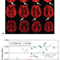
 FIGURE 19.2. Influence of an intersecting labeling plane (labeling the right internal carotid artery) through the imaging slice. Five different conditions are shown (from left to right): First column: No presaturation and no postsaturation. Second column: A conventional presaturation module (90-degree radiofrequency [RF] pulse in combination with a dephasing gradient) and no postsaturation. Third column: Conventional pre- and postsaturation. Fourth column: WET (water suppression enhanced through T1 effects technique) presaturation and no postsaturation. Fifth column: WET presaturation in combination with conventional postsaturation. Without any saturation pulses or only a conventional saturation preceding the labeling, the labeling plane becomes apparent even in the unsubtracted label images. Whereas conventional saturation model pre- and postlabeling seems to limit the influence on the label image (upper row), an artifact still becomes apparent in the subtraction images (lower row). WET presaturation eliminates almost all influence of the intersecting labeling slice, especially when combined with a conventional postlabeling saturation module. (Ring artifact due to residual fat signal that folds back because SENSE was applied in the acquisition; note that this artifact does not show in the subtraction images.) |
The tilted labeling plane should be considered the simplest labeling approach based on spatially selective RF pulses because it limits the labeling inversion pulse only in a single direction (i.e., the slice selection direction). By varying the gradient and RF waveform, it is also possible to limit the inversion pulse in two or three directions.13,14 The development of such spatially selective RF pulses is an active field of research, mainly for applications other than rsASL, for example, to enable restricted field-of-view imaging in fMRI or region-of-interest selection in MR spectroscopy. Although historically such RF pulses were of limited use owing to their long duration, the introduction of parallel transmit has enabled the shortening of the pulse duration by factors of 4 to 8.15 Davies and Jezzard14 already used this method in 2003 to label a single artery by means of a pencil-beam inversion pulse. A principal disadvantage of such a pencil-beam approach is that only a small part of an artery can be inverted, because the pencil-beam approach inverts a box-like region and does not allow curved arteries to be followed. This can partly be overcome by repeating the inversion pulse multiple times (Davies and Jezzard inverted the siphon three times), but this will limit the possibilities to quantify the cerebral blood flow (CBF) and involves an inherent dependency on the blood velocity, making the application in patients troublesome. Although this method never has become readily available to clinical users primarily because of the complexity of its implementation, it can be expected that it will become more popular in the years to come—at least for basic science research—owing to all efforts put into parallel transmit.
Rotating Labeling Gradient
Continuous ASL (CASL) and pCASL techniques are based on a long labeling period (1.5 to 3 seconds) consisting of a net (slice-select) gradient switched parallel to the flow direction of blood while RF is played out either continuously or as a train of RF pulses (see Chapter 17).7,16 For non-(regional)-selective ASL, the gradient always points in the same direction; however, by adding an additional gradient that rotates around the vessel of interest
(see Fig. 19.4), only on top of the artery (i.e., in the middle of the cone), effective labeling is achieved. At the top of the vessel, additional gradient is effectively zero, whereas outside of the vessel, the gradient is pointing in random orientations (see red cone in Fig. 19.4: Only on top of the artery the rotating gradient results in zero magnetic field strength for the total labeling duration; on other locations the value will change for the different gradient orientations as indicated by the green lines). A rotating gradient is achieved by changing in time the gradient strength in both the x– and the y-directions: At the start the full gradient strength is applied along the x-direction, and then gradually the gradient strength in the y-direction is increased while decreasing the gradient strength in the x-direction until the moment that the full gradient strength is played out along the y-direction—and a 90-degree rotation has been performed. By choosing a cosine function for the x-gradient and a sine function for the y-direction, a circular, rotating gradient can be achieved.
(see Fig. 19.4), only on top of the artery (i.e., in the middle of the cone), effective labeling is achieved. At the top of the vessel, additional gradient is effectively zero, whereas outside of the vessel, the gradient is pointing in random orientations (see red cone in Fig. 19.4: Only on top of the artery the rotating gradient results in zero magnetic field strength for the total labeling duration; on other locations the value will change for the different gradient orientations as indicated by the green lines). A rotating gradient is achieved by changing in time the gradient strength in both the x– and the y-directions: At the start the full gradient strength is applied along the x-direction, and then gradually the gradient strength in the y-direction is increased while decreasing the gradient strength in the x-direction until the moment that the full gradient strength is played out along the y-direction—and a 90-degree rotation has been performed. By choosing a cosine function for the x-gradient and a sine function for the y-direction, a circular, rotating gradient can be achieved.
Related posts:


Stay updated, free articles. Join our Telegram channel

Full access? Get Clinical Tree


