Chapter 7 Electricity (DC)
Chapter contents
7.1 Aim
The aim of this chapter is to introduce the reader to the concept of electron flow as a means of conducting electricity. Factors affecting the resistance to this flow will be explored and Ohm’s law will be discussed. The consequences of resistance in terms of electrical ‘power loss’ will be discussed and the practical implications of this in the design of X-ray-generating apparatus will be considered.
7.2 Introduction
In Chapter 6 we considered the behaviour of static electrical charges. This chapter considers the behaviour of electrical charges which are unidirectional in their movement – direct current or DC electricity. Batteries produce a DC current and it is also found in the form of a rectified supply (see Ch. 28). In a vacuum, liquid or gas (e.g. in an air ionization chamber; see Ch. 27), both positive and negative charges move with relative freedom. These charges are called ions. In a solid, however, the atomic nuclei are relatively tightly bound to other atoms and so take no part in the flow of charge. The electrical properties of a given solid are determined by the way in which the orbiting electrons behave.
7.3 Simple electron theory of conduction
To explain why some materials readily allow a flow of electrons (i.e. are good electrical conductors) and other materials will only allow electron flow in extreme conditions (i.e. are good insulators), we need to look more closely at the structure of the atom. This chapter will only look at atomic structure in terms of explaining the electrical properties of the material and there will be a fuller description of the atom in Chapter 18.
The nucleus of the atom contains protons (+ve charge) and around this in orbitals are electrons (−ve charge). We can appreciate that electrons near the nucleus experience a high level of attraction (unlike charges attract) and are thus said to be tightly bound. Electrons in the more remote orbitals experience less force of attraction from the nucleus (remember F ∝ 1/d2) and are also repelled by other electrons which lie between them and the nucleus and so are said to be more loosely bound. Because the electrons in a given single atom are influenced by only that atom, the electrons lie at discrete energy levels, as shown in Figure 7.1A.
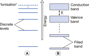
Figure 7.1 (A) Electron energy levels in a solitary atom. (B) Electron energy bands in an atom of a solid.
When electrons are brought closer together, as in a solid, the orbitals of the electrons are strongly influenced by the proximity of neighbouring atoms. This means that electrons are no longer at discrete energy levels but that they are now within a band of energies. This situation is shown in Figure 7.1B.
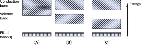
For the purpose of this discussion, only the outer two energy bands are of interest to us: the valence band and the conduction band. The valence band is that band which contains the outermost electrons of the atom and may be partially or completely full of its permitted maximum number of electrons. The configuration of electrons in the valence band determines the chemical properties of the atom, i.e. its ability to form chemical bonds with other atoms. If electrons exist further away from the nucleus than the valence band, then their energies lie in the conduction band. This band is populated with electrons that have, for some reason, become free from their original atoms. Because of this, once an electron is in the conduction band of a solid, it is able to move relatively freely and may take part in electrical conduction through the material. A material with a large number of electrons in the conduction band is a good electrical conductor whereas a material with no electrons in the conduction band is a perfect electrical insulator. Whether or not a material is a conductor, an insulator or a semiconductor is determined by the number of electrons in the conduction band. This number is in turn determined by the size of the forbidden energy gap (E) which exists between the top energy of the valence band and the bottom energy of the conduction band. The arrangement of the valence and conduction bands for conductors, semiconductors and insulators is shown in Figure 7.2. Each of the above will now be considered individually.
7.3.1 Electron arrangements in a conductor
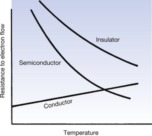
As can be seen from Figure 7.2A, the conduction band and the valence band of energies overlap in a conductor. As a result, a large number of electrons always exist in the conduction band and because of this there is a ready exchange of electrons between the valence and conduction bands. This means that these electrons can be moved through the solid with little resistance to their flow. The main opposition to their flow arises from collisions with other electrons or atoms. If the temperature of the conductor is increased, there is an increase in the vibration of the atoms and a corresponding increase in the likelihood of collision with moving electrons. From this we can see that the opposition (or resistance) to the flow of electrons in a conductor will increase with an increase in its temperature.
As mentioned in Section 7.3.1, the main cause of resistance to the flow of electrons in a conductor is collisions with other atoms. It would seem logical to suggest that if the vibration of the atoms could be reduced, or even stopped, then the resistance of the conductor could be reduced. This is done by cooling the conductor to temperatures close to absolute zero. At these temperatures, atomic vibration ceases to exist and so flow of electrons through the conduction band is virtually unimpeded. Materials operating in this mode are known as superconductors and this technique is used to produce the large magnetic field required for magnetic resonance imaging (MRI).
7.3.2 Electron arrangements in a semiconductor
In a semiconductor, there is a gap between the maximum energy of the valence band and the minimum energy of the conduction band (Fig. 7.2B) and so electrons need to be given energy to bridge this gap and flow through the material (this will be discussed in more detail in Ch. 15, which deals with semiconductors). Thus, semiconductors have a greater resistance to the flow of electrons than conductors. If we increase the temperature of the semiconductor, we will increase the energy of the electrons in the valence band and so make it easier for them to transfer to the conduction band and move through the solid. Thus, increasing the temperature of a semiconductor will reduce its resistance to the flow of electrons.
7.3.3 Electron arrangements in an insulator
In an insulator, there is a significant gap between the maximum energy of the valence band and the minimum energy of the conduction band (Fig. 7.2C). This means that electrons cannot readily bridge this energy gap, and so the conduction band contains no electrons, making conduction impossible. If the material is heated, then the electrons in the valence band gain energy, and so the gap between the valence and the conduction bands is narrowed, making it more likely that electrons can jump the gap. Thus, increasing the temperature of an insulator reduces its resistance.
The effect on the resistance to the flow of electrons of increasing the temperature is shown in Figure 7.3.
7.4 Electric current
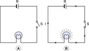
• There must be a source of electric potential difference (see Sect. 6.8.2).
• There must be a complete circuit around which the electrons are able to travel.
These two points are illustrated in Figure 7.4. The battery (B) is a source of potential difference, but if the switch (S) is open (as in Fig. 7.4A), no electric current flows and the bulb does not light up. When the switch is closed (Fig. 7.4B), a complete circuit exists around which electrons are able to flow and so the bulb lights up. The potential difference may be thought of as the driving force that causes electrons to flow, while the current is the rate of flow of electrons, i.e. the number of electrons passing a given point in unit time.
Thus, we can say mathematically:

From Section 6.4, we know that a charge of 1 coulomb is equivalent to approximately 6 × 10¹⁸ electrons so 1 ampere is simply this number of electrons passing a point in 1 second.