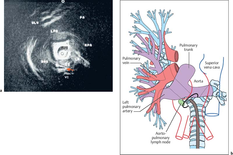
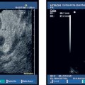
28 Endobronchial Ultrasound with Miniprobe Radial Scanning In the bronchi, the endoscopist’s view is restricted to the lumen and internal surface of the airways. Intramural processes and those adjacent to the airways can only be assessed using indirect signs. The clinical staging of lung cancer corresponds to pTNM in only 60% of cases. For these reasons, there was a need to improve the tools available for endoscopic diagnosis. As external mediastinal ultrasonography and transesophageal endosonography were insufficient for the imaging of mediastinal structures, there was a need for a different solution involving the use of miniaturized probes of the type used for endoscopic ultrasonography (EUS)1 and cardiovascular endosonography, preliminary experience with which had been reported in endovascular sonography of the pulmonary artery to exclude tumor invasion.2 Miniprobes: General Considerations During the 1990s, miniaturized probes with a frequency of 7.5 MHz began to be used. Probes with 12 and 20 MHz also became available later. The first probes had a diameter of 3 mm, with a mechanical single-element transducer at the tip rotating at ≈400rpm and producing a 360° image perpendicular to the axis. Due to the large diameter of the probe, it was mainly used during rigid bronchoscopy, with a metallic tube serving as a guide. To achieve better contact with the tracheobronchial wall, a latex balloon was attached at the tip of the probe, which was filled with sterile water via a side port. Later, models with a diameter of 2.5 mm became available that were capable of being introduced via biopsy channels at least 2.8 mm in diameter in regular flexible fiberscopes. These have been available commercially since 1999 (Olympus UM-2 R/3 R, with an MH-240 driving unit and EU-M20 and 30 processors). In addition, dedicated balloon catheters are available that can be attached to the probe at the connector for the driving unit (Olympus UM-BS20-26 R) (Fig. 28.1). A special feature is the O-ring at the tip, which fits to a notch at the tip of the probe (Olympus UM-BS20-26 R). When the balloon is overinflated or pressure is exerted due to coughing, the tip slips off the probe, preventing rupture with fragments dislodging into the lung. This comparatively simple device meets three requirements for optimal imaging: firstly, 20-MHz probes, with their high resolution, can be used; secondly, as the water in the balloon in front of the transducer shifts the focus to the periphery, the depth of penetration is sufficient for imaging the surrounding mediastinal structures; and thirdly, the balloon provides complete circular contact with the airway wall, which is essential for orientation. Miniprobes are fragile and have to be handled very delicately. The transducer and connecting driving wire are protected from friction inside the plastic sheath by applying a gel solution. As this is not completely air-sealed, small air bubbles may collect in front of the transducer and interfere with the image. The devices should therefore be stored in a hanging position, with the connector upward and the tip of the probe downward. If a bubble has collected in front of the transducer, the catheter should be held ≈ 40 cm proximal from its tip and the end should be gently rotated like a lasso, so that the centrifugal force drives the gel toward the tip and the bubble travels proximally. After the probe has been inserted into the balloon catheter and fixed at the connector, the balloon catheter should be completely filled with sterile water until drips appear at the distal end. Saline solution should not be used, as the salt may crystallize on the tip of the probe and interfere with the ultrasonic signal. After filling of the catheter, the O-ring of the balloon is slipped onto the groove on the tip of the catheter. This can be achieved with the fingertip or with the help of a dedicated rubber device. Exerting too much force on the tip, which results in bending or even kinking of the tip, should be avoided. The balloon is then refilled. If a few air bubbles are still observed, the balloon is kept with its tip downward, so that the air collects at the end of the catheter. The air is evacuated by suctioning the water from the balloon with the syringe. This should always be held in such a way that the air is above the fluid and is not flushed back into the catheter. Fig. 28.1a, b a The complete miniprobe system. b The miniprobe is introduced via the biopsy channel of a video bronchoscope. The probe is armed with a balloon catheter. The grayish mechanical rotating transducer can be seen inside the balloon (arrow). The miniprobes should always be used with bronchoscopes that have an appropriate biopsy channel at least 2.8 mm in diameter when applied with the balloon sheath. We prefer to use a little medical silicone on the tip before insertion. During introduction, the assistant should apply suction to completely evacuate the balloon, preventing dislocation from the tip or damage due to friction within the biopsy channel. The probe should never be advanced when the tip of the endoscope is in a sharply bent position. It should also not be activated then, as the transducer may be fixed while the wire is still rotating and could therefore shear off. Force should never be used while advancing the probe, neither when there is resistance against the tip nor by pushing the probe forcefully sideways against the wall. Inside stenoses and in the periphery as well, the probe should never be advanced using force, as the tip easily becomes kinked in this way. The balloon should never be overinflated. Particularly when the probe is being advanced inside narrowing airways or if the patient coughs, the balloon’s safety feature will not work with overinflation, as the O-ring is not able to slip off; in this case, the balloon may fracture and latex fragments may be lost inside the lung. Technique of Endoscopic Bronchial Ultrasonography The miniprobes are inserted through the biopsy channel of flexible scopes with a diameter of at least 2.8 mm. Precise placement is performed with endoscopic visualization, and once the balloon is in place, it is filled with sterile water until firm contact with the wall is established. Adequate contact is confirmed by a complete circular image of the bronchial wall and the surrounding structures. The development of the image can be compared to a sunrise, in which all of the structures gradually become visible. With the patient under local anesthesia, complete inflation of the balloon is possible in bilaterally ventilated lungs after sufficient preoxygenation, up to the main bronchi and even the trachea. Complete obstruction of a remaining main bronchus after contralateral resection, or resection of the trachea, can therefore be tolerated for up to 2 minutes with sufficient sedation. If necessary, the bronchoscope can be introduced via a larynx mask. In these cases, general anesthesia may be preferable, as it can provide additional time for imaging of the mediastinal structures. In our view, this procedure is well justified due to the useful additional information that can be obtained. We have never observed barotrauma during complete obstruction, since according to our measurements even with high-frequency jet ventilation, the pressure distal to the balloon during filling rapidly drops to zero after complete inflation. If the patient is not able to tolerate complete obstruction at all, the balloon can be partially filled and applied with semicircular contact. Motion artifacts with irregular rotation were observed when early probes were used inside calibration phantoms, causing considerable distortion of the circumferential sector images—whereas the radial distances were measured correctly, as reported with other systems. However, the image construction is still slow enough for respiratory motion to create artifacts. As these are not synchronous, they can be readily differentiated from pulsations. Most frequently, a multiple ring reflection is caused by the strong echo of the balloon. As the airways are surrounded by strongly reflecting structures, multiple reflex echoes and mirror and comet artifacts are observed in endoscopic bronchial ultrasonography (EBUS), as in other applications. This applies in particular to the adjacent lung surface, vertebral column, calcified cartilage, and lymph nodes. Triangular distortion of lymph nodes and attenuation of the outer contours in echogenic structures is also very common with 20-MHz probes. Air bubbles in the balloon can cause shadows or image distortions resembling a “rabbit’s ear” (Fig. 28.2). Fig. 28.2 Artifacts in bronchial imaging. Rotation artifact: on the left, in the 9-o’clock position, there is an interruption in the contour of the wall and the adjacent pulmonary artery (red arrow). In this position, the image is refreshed after one circulation of the transducer. If the structures have in the meantime been displaced by breathing, pulsation, or movement of the bronchoscope, the interruption can be observed. Repeat echoes: in the 11-o’clock position, there is insufficient contact between the balloon and the bronchial wall. The strong echo from the balloon is repeatedly reflected in quarter-circles (three arrows). Shadows due to air: also in the 11-o’clock position, small bubbles have collected inside the balloon (arrowhead). These are causing the triangular shadow, in which the structures are lost. However, the strong echoes from the balloon are still visible. Another shadow is seen in the 3-o’clock position (yellow arrow), where a bronchial branch is emerging and the air inside is reflecting the ultrasound and causing the shadow. Fading: as the lower energy from the 20 MHz is dissipating inside the tissue by dispersion and absorption, the external boundary of the lymph node (LN) is not visible. In animals and in resected human specimens, we have observed a seven-layered structure in the central airways in vitro. This is in contrast to the findings of other groups, who have described three layers, or more recently five,3,4 in some cases due to the use of probes with a lower resolution. The first (innermost) layer, the mucosa, has a highly echogenic structure that is mostly confluent with the echo of the balloon and only becomes visible with high magnification. The second layer has low echogenicity and represents the submucosa. In normal conditions, it can be easily differentiated from the mucosa and from the third layer, the strongly reflecting internal surface of the cartilage, which we term “endochondrium.” The spongiform internal structure of the cartilage, the fourth layer, is hypoechoic again, whereas a fifth hyperechoic layer represents the external surface of the cartilage (perichondrium). It is a little-known fact that the central airways are surrounded by a double layer of loose and dense connective tissue, representing the sixth (hypodense) and seventh (hyperdense) ultrasonic layers (Fig. 28.3). This seven-layered structure has been confirmed in another prospective experimental study.5 Fig. 28.3 The structure of the wall of the central airways. At high magnification, the seven-layered structure is clearly visible with the 20-MHz probe. The three layers of cartilage, consisting of endochondrium (EC), an internal spongiform structure (IC), and perichondrium (PC), are accompanied by mucosa (M) and submucosa (SM) on the inside and loose connective tissue (LCT) and dense connective tissue (DCT) on the outside. The anatomical illustration shows the high resolution provided by the ultrasound image, at less than 1 mm. In vivo, the complex structure can be only seen with high magnification, whereas at medium and low-powered magnification, the delicate layers are confluent with the strong echo from the supporting cartilages. At the dorsal membranous wall and in the periphery distal to the lobar bronchi, the structure only consists of three layers. The layered structure is not visible with the 7.5-MHz ultrasound bronchoscope. Orientation within the mediastinum is difficult. This is mainly due to the complex anatomy, as well as to motion artifacts and pulsation, but it is also due to the very unusual planes that are present. The plane of the circumferential image of the miniprobe is perpendicular to the axis of the probe. While the planes inside the trachea are comparable to those in horizontal computed tomography (CT) images, following the oblique course of the airways, the images tilt more and more as one follows the main bronchi until a coronary plane is reached in the distal left main bronchus, or even an inverse horizontal plane on entering the apical segments of the upper lobes. For orientation, it is useful to recognize key anatomical structures and their relationship to the airways and to each other, rather than to observe the position of the probe. Familiarity with the anatomy is essential for orientation. The image has to be set accordingly, so that landmark structures that are found only ventral or dorsal to the bronchus, such as the esophagus or pulmonary artery, are in the correct position. It is helpful to place the tip of the bronchoscope close to the balloon, or even better to look inside the balloon and follow the motion of the probe on the ultrasound image, while the tip of the bronchoscope is flexed up and down. Once the sagittal orientation is set and the EBUS image is adjusted with the scroll ball on the keyboard, right and left orientation can be set accordingly, with lateral motion being observed on the ultrasound image and the reverse key being used if necessary. Fig. 28.4a, b Mediastinal anatomy a Thetypical ultrasound anatomy of the proximal left main bronchus (LMB) and surrounding structures. Dorsally lies the esophagus (ES, above the red arrow); to the right of the esophagus, there is a borderline lymph node (LN); on the left lie the descending aorta (DAO) and the beginning of the aortic arch. Behind the esophagus and in front of the vertebral column (VC), an intercostal artery is crossing to the right (red arrow). Ventrally, the main pulmonary artery (PA) and its left (LPA) and right (RPA) branches are visible. On the left, the pulmonaryupper lobe vein (ULV) crosses towards the left atrium. O marks the 12 o’clock position. b The diagram illustrates the anatomy and the ultrasound plane (reproduced with permission of Wang et al.6). Vessels are easily recognized by their low echogenicity and by pulsations; arteries and veins differ in characteristic ways. However, in the periphery the variations are so complex that this may become impossible. Observation of the pulse oximeter is often helpful. Lymph nodes are easily differentiated by their comparatively higher echogenicity. As filling of the balloon catheter with water shifts the focus more distally, even with the 20-MHz probes the depth of penetration can be up to 5 cm. Thus, the left atrium and mitral valve can frequently be seen from the left main bronchus. Near the bifurcation, the main pulmonary artery and its branching into the left and right main arteries can be seen ventrally. Dorsally, the descending aorta, the multilayered structure of the esophagus, and the vertebral column are clear landmarks for orientation. The aortopulmonary window can be inspected and approached from the left main bronchus (Fig. 28.4).6 Ventral to the right main bronchus, the right pulmonary artery is always found, crossed by the azygos vein, which can often be followed as far as its confluence with the vena cava, which is situated beside the root of the aorta. Slightly more proximally, at the level of the tracheobronchial angle, the esophagus is seen crossing to the left, accompanied by the azygos vein, which crosses forward at the right toward the vena cava. Pathological soft-tissue structures are easily differentiated from these structures. Further distally, in the intermediate bronchus, the pulmonary artery and pulmonary vein are found ventrally. At the level of the middle lobe bronchus, the segmental artery for the apical segment of the lower lobe (S6) can be seen crossing laterally beside the intermediate bronchus, whereas the bright reflection of the adjacent pleura of S6 is a significant dorsal landmark. In the periphery, conditions are less favorable, as the surrounding air is strongly reflective and thus frequently prevents detailed analysis of the bronchial wall and adjacent vessels. Despite this, some Japanese authors have even succeeded in analyzing the alveolar structures with EBUS.7
![]()
Stay updated, free articles. Join our Telegram channel
 Storage and Preparation
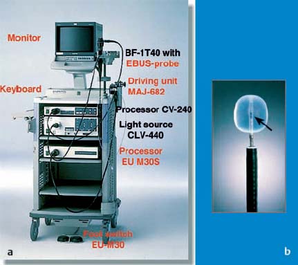

 Imaging Artifacts
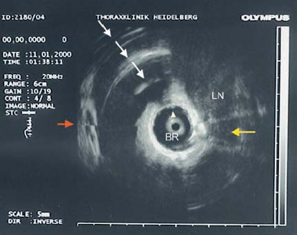
 Sonographic Anatomy
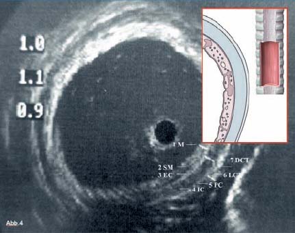


Full access? Get Clinical Tree


