While clinical evaluation of breast implants and their complications can identify capsule contracture and rupture of saline implants, the identification of silicone implant failure is best accomplished by silicone specific protocols for MRI with orthogonal acquisition. Such imaging can also help resolve other clinical problems. Following a brief overview of the history and development of commercial use of silicone implants and alternatives, this article outlines the approach toward optimal imaging and expected results.
Key points
- •
The linguine sign represents complete collapse of the envelope within the fibrous capsule and is the most specific sign of implant failure.
- •
The inverted-loop sign (also called hang-noose or keyhole sign) represents the most common form of intracapsular rupture.
- •
MR imaging of silicone implants requires no intravenous contrast but does require orthogonal image acquisition at sufficiently narrow sections to detect small signs of implant failure.
- •
MR imaging is the most sensitive imaging method to detect and evaluate breast silicone implant integrity.
The history of development and commercial use of breast silicone implants is exceptional. Developed and tested before US Food and Drug Administration (FDA) guidelines for medical device implantation, reports of various complications were raised in the 1980s, including low birth weights of infants born to women with silicone implants and increased incidence of brain tumors and suicide rates in women with implants. The most widely publicized concern involved immunologic responses resulting in collagen vascular diseases. Given such concerns, coupled with the relatively unregulated introduction into the marketplace, the FDA, as well as Canada’s HealthCanada, placed a moratorium on commercial availability of silicone breast implants in 1992. Their use was banned except under stipulated protocols limited to reconstructive purposes. Other countries expressed concern but took no regulatory action. Eleven years later, following 15 studies involving 34,000 subjects with implantation follow-up of 7 to 15 years, both countries reversed their decision and allowed implants to be reintroduced into the commercial marketplace with an agreement to provide post-market approval studies (relatively unprecedented) during the next 10 years. By this time, only two manufacturers, Mentor (Santa Barbara, CA) and what is now Allergan Medical (Santa Barbara, CA), were producing silicone implants.
There have been, and continue to be, innumerable variations on the types of silicone breast implants using silicone. Different shapes, sizes, components, shell texturing, and fixation patches, as well as valves, have been developed to provide sufficient variation for women and their plastic and reconstructive surgeons to select one based on multiple factors, especially body habitus. Current FDA-approval criteria provide formidable challenges to the companies seeking to propose new devices because post-market approval studies continue to provide data. Most breast implants currently in use are single-lumen devices, with the second most common device being a silicone inner lumen and an outer saline lumen.
Before the widespread use of silicone implants, various foreign substances were injected directly into the breast, most notably paraffin and free silicone ( Fig. 1 ). This resulted in considerable breast hardening and pain, and these breast-injected substances were banned in many countries. Mammography is usually sufficient for demonstrating such substances, which may interfere with the primary purpose of this modality as a tool in detecting breast cancer, though MR imaging may be useful. Of interest, prognostic characteristics for breast cancer of women with implants are comparable to those without implants, although sensitivity of mammography is lessened. The presence of silicone within the breast may interfere with cancer detection, but no causal relationship between silicone and breast cancer has been shown. Ultrasound is of little value for such patients because the reverberative artifact produced by the granulomatous response of the breast to these diffuse injections obscures breast detail ( Fig. 2 ). Even tumor-specific breast MR imaging protocols are compromised by such injections, which can create long-standing inflammatory responses that enhance with the injection of gadolinium contrast material.


Mammography alone can provide evidence of some types of implant failure in which the silicone material, which is denser than fibroglandular tissue, is recognized within the parenchyma. In the absence of a history of implant revision, the presence of extracapsular silicone found in the breast parenchyma indicates that an intracapsular rupture has occurred. A silicone implant is usually placed behind the pectoral muscle (subpectoral) or behind the breast tissue and, sometimes, deep fascia but in front of the pectoral muscle (subglandular). The breast immune system recognizes the device as a foreign material and responds with a fibrous response (as with other foreign bodies) to seal it off. Thus, a fibrous capsule is formed ( Fig. 3 ). Silicone that leaks from the silicone envelope is, therefore, intracapsular and, if it escapes from the encapsulating fibrous structure that surrounds the implant, is called extracapsular ( Fig. 4 ). Fibrous capsules can become thick, hard, uncomfortable, and even impress on the implant. Historically, surgeons would apply manual (and sometime even instrument) manipulation to help reverse the development of a thick fibrous capsule (closed capsulotomy). This practice was abandoned because it converted a clinically unrecognized intracapsular rupture to an extracapsular one. Silicone in breast tissue incites a granulomatous reaction that may produce a palpable lump and/or obscure breast parenchyma.


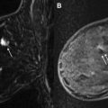
Because silicone oils can dissociate from the gel, and because the implant shell is also silicone and, therefore, a semipermeable membrane to the transit of such oils, lymphatic drainage of silicone oils may cause accumulation in an intramammary or axillary lymph node, making it more dense but, perhaps, not dense enough to recognize the silicone by radiographic attenuation. Performance of silicone MR imaging resolves this issue ( Fig. 5 ).

Mammography cannot, in general, detect intracapsular rupture, which accounts for most implant failures. Experimental and clinical experience has shown that ultrasound can detect intracapsular ruptures but with considerably less sensitivity and specificity than MR imaging. Where breast MR imaging is not available, ultrasound has been used with variable success to evaluate implant integrity.
Sometimes, medical records are not satisfactory in determining what kind of silicone breast implant was surgically placed and it may be difficult for the interpreting radiologist to ascertain. For example, the presence of a double-lumen implant on one side, with the usual outer saline component intended to protect the inner silicone lumen, and a single-lumen implant on the contralateral side, should raise the possibility of sufficient trauma to the side with a single lumen where intracapsular implant rupture may have occurred. This too can be resolved with MR imaging (assuming the same implants have been placed bilaterally, which is the usual but not inviolate situation). Finally, mammography may be uninterpretable due to the implant, often because of the placement of more than one (stacked) implant. MR imaging will more clearly delineate the separate implants that have been placed ( Fig. 6 ).

MR imaging of implants
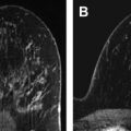
Higher field strengths (at least 1 T) are required for proper imaging of breast silicone implants due to the need for sophisticated imaging sequences and emphasis on required tissue contrast and resolution to detect small implant failures ( Fig. 7 ). The coupling of breast-specific coils is the second component of satisfactory imaging that insures proper transmission and faithfully registered imaging series. If dedicated breast coils are not available, coils anatomically approximating the region of interest, such as shoulder coils, can be used. However, current standards usually require breast coils more suited for the anatomy of the breast. Studies are performed in the prone position to minimize respiratory artifact and to allow the implant to be imaged in maximum size, as opposed to the gravity-oriented compression involved in supine positioning. Even observing this approach, some respiratory motion and pectoral muscle contraction will compromise resolution. Most implant failures will be detected; however, measurement of the fibrous capsule thickness, which may be of clinical interest, is difficult to accurately obtain under such conditions.

Silicone is a ubiquitous substance with uses ranging from a lubricant for hypodermic needles to the making of a child’s toy, Silly Putty. Medical-grade silicones are usually composed of dimethyl polysiloxane with the customary hydrogen-related MR imaging signal derived from the protons of the methyl groups ( Fig. 8 ). Manufacturing strategies provide for varying degrees of polymerization so that cross-linkages between methyl groups will allow for a harder or softer substance. In general, silicone elastomer shells are solid, with the inner silicone component more liquid in an attempt to provide a desired cosmetic ptosis. Recent development of cohesive implants provide a more semisolid inner silicone component. However, after a period of time at physiologic temperatures in the body, these more cohesive inner components likely become more liquid. The signs of implant failure are the same as earlier liquid types.

The MR sequences that are used in silicone implant imaging are strategically developed to separate three main components: water, fat, and silicone. They are determined by the relative Larmor precession frequencies, as well as the T1 and T2 properties of the tissue (including muscle). At 1.5 T, which is the most commonly used magnet strength used for implant imaging, the relative resonance frequency of silicone is approximately 100 Hz lower than fat and 320 Hz lower than water. This limits the ability to use certain imaging protocol sequences (see Fig. 8 ).
For example, if chemical fat suppression techniques are used, the sending of a radiofrequency (RF) pulse downfield of approximately 220 Hz is used to suppress fat. However, the fat and silicone resonance frequency peaks are insufficiently separated so that the silicone signal is suppressed almost as much as the fat signal. In addition, different scanners (depending on shimming and age) may insufficiently separate the fat and silicone peaks when viewed on the monitor. On the other hand, chemical water suppression at 1.5 T centers on the fat-resonance frequency to send an RF pulse upfield approximately 220 Hz and does not interfere with the silicone signal. Many strategies involve imaging implants with and without water suppression so that saline components or surrounding fluid can be identified.
Because the relaxation times of fat are shorter than silicone, even though their processional frequencies are close, the difference can be exploited to suppress the fat signal by using inversion recovery techniques with a short T1 (STIR). This approach, used at the author’s center, is outlined in Box 1 .
Bilateral axial T2-weighted STIR
Two-dimensional FSE IR (flow comp, sequential, tailored RF, Asset)
TE 60, Freq 320, TR 6725, Phase 192, T1 150, NEX 2, ETL 8, FOV 32, band 20.83, Freq direction AP, slice thickness 3 mm, gap 1 mm, flow comp slice, shim on
Sagittal of each breast: IR
TE 50, Freq 256, TR 6725, Phase 160, T1 150, NEX 2, ETL 7, band 15.63, FOV 24, Freq direction AP, slice thickness 3 mm, gap 1 mm, shim auto
Other techniques can be used to selectively image silicone, all aimed at separating the silicone signal from water or fat. Chemical shift imaging can separate the three frequencies of fat, water, and silicone. One of the original techniques for implant imaging has been, and continues to be, modified: the three-point Dixon technique in which a single MR sequence is used to demonstrate silicone only.
The implant must be imaged in two orthogonal projections for proper evaluation and involves no intravenous gadolinium contrast injection. Projections may include coronal, sagittal, and axial images, usually the latter two. Using the described sequences, the fibrous capsule and elastomer shell show no signal. Because of reimbursement schedules in the United States, as well as limited magnet time and patient nonmotion compliance (a universal challenge), some centers provide both breast silicone implant and tumor studies at one sitting. Although one-dimensional imaging (sometimes with reformatting) may be sufficient for tumor imaging, this approach will miss small implant failures. Most tumor sequences involve a T2-weighted sequence that affords a first approximation of implant integrity in one projection. Orthogonal imaging will add a small amount of time to the sequence if full implant integrity evaluation is desired. In addition, implant evaluation should involve section slices no greater than 4 mm with a possible 1 mm skip to provide sufficient resolution and reliability of data.
Normal and Abnormal Appearance of Breast Silicone Implants
Breast silicone implants are composed of an elastomer shell, within which more liquefied or cohesive liquid silicone is present. They are designed to approximate the cosmetic ptosis of a normal breast and, as such, are not meant to be taut. Consequently, there is mild rippling or undulation of the implant, most visible on coronal imaging. In addition, normal folds will occur within the malleable device and extend from the edge of the shell inward for variable distances, occasionally causing confusion with possible signs of rupture. Sometimes, fibrous capsule bands may impinge on the implant that can create diagnostic confusion on conventional imaging. Other times, the capsule will impress or efface the implant, which may also cause confusion. The absence of more specific signs of failure, however, will distinguish these variants from implant rupture ( Fig. 9 ).

When breast implants fail, the outer elastomer shell becomes discontinuous. A large percentage of instances occur during surgical implantation when either instrument violation of the implant or placement of the implant in a position where the shell overlaps and creates shear forces against itself causes a rent in the elastomer envelope. When this happens, the rent in the shell allows the liquid silicone to escape the shell, confined only by the surrounding fibrous capsule. Over time, the escaped silicone will surround the shell and cause it to collapse into the pool of remaining silicone. The shell, due to its cross linkages, produces no silicone signal. On MR imaging, a dark or wavy line is seen “floating” in the free silicone that is now confined only by the capsule. This curvilinear appearance, called the linguine sign, may be a single structure or several structures and is the most specific sign of implant rupture ( Figs. 10 and 11 ). Long radial folds can rarely be confused with the linguine sign, but tracing the dark signal on its path to the shell resolves the issue, provided that proper imaging protocols have been used.


Because silicone oils can dissociate from the gel, they can osmotically transgress the intact elastomer silicone shell and are, therefore, limited by the fibrous capsule. These oils are sticky and over time cause adherence of the shell to the fibrous capsule. Under these circumstances, if a rent or break occurs in the elastomer shell, the liquid silicone gel will egress, as previously noted. However, it can no longer circumferentially extend between the shell and the capsule as it did in developing a linguine sign. Instead, it is confined by the shell-capsule adherence, thus the leakage is more focal. As a consequence, the exiting gel accumulates focally and may begin, under the mechanical pressures of normal activity such as unconscious prone sleeping, to invaginate the otherwise intact portions of the elastomer shell. This invagination has been referred to as an inverted-loop sign, a keyhole sign, or a hang-noose sign, all three terms representing the same phenomenon. These signs are more common than the linguine sign on MR imaging as showing rupture, but may be less specific. A narrow inverted sign, especially with implant motion and suboptimal slice thickness MR imaging protocols, may be confused with a radial fold. Attention to suggested slice thickness and skip parameters, as well as orthogonal imaging, usually resolves these discrepancies. Depending on the anatomic extent of the oil adhesions of the capsule and envelope, as well as the external pressures imposed on the implant during failure, the base of this invagination may be broader. This appearance has been called a subcapsular line. It is a dark signal, paralleling the dark signal of the fibrous capsule, with silicone signal on both sides ( Fig. 12 ).

Related posts:
 Breast Magnetic Resonance Imaging Technique at 1.5 T and 3 T
 Updates and Revisions to the BI-RADS Magnetic Resonance Imaging Lexicon
Screening MR Imaging Versus Screening Ultrasound
BI-RADS 3 for Magnetic Resonance Imaging
Updates and Revisions to the BI-RADS Magnetic Resonance Imaging Lexicon
Screening MR Imaging Versus Screening Ultrasound
BI-RADS 3 for Magnetic Resonance Imaging
 Magnetic Resonance Imaging–Guided Biopsy of the Breast
 Radiologic-pathologic Correlation at Breast MR Imaging
Stay updated, free articles. Join our Telegram channel

Full access? Get Clinical Tree


