Magnetic resonance (MR) imaging is now an accepted component of standard breast-imaging practice. This article reviews the fundamentals of performing an MR imaging–guided biopsy using a grid localization system, and discusses many of the finer points and nuances of the procedure. Tips and tricks found useful at the authors’ institution are included, although multiple variations also exist. Performing effective and efficient MR imaging–guided biopsy depends both on deliberate preparation (of the proceduralist, the patient, and the equipment) and on deliberate positioning (of the patient and the sampling device).
Key points
- •
Magnetic resonance imaging is now an accepted component of standard breast-imaging practice.
- •
Conscious, deliberate efforts in the preparation and positioning phases will improve the efficacy of the procedure as a whole.
- •
The concepts of controlled compression and directional sampling of MRI-guided biopsies need to be understood and the importance of sampling adequacy evaluation and radiologic-pathologic correlation emphasized.
Magnetic resonance imaging (MRI) has transformed breast imaging. One of the most touted features of this modality is its tremendous sensitivity, reaching up to 100%. However, the Achilles’ heel of MR imaging of the breast is its limited specificity, with well-documented overlap between benign and malignant lesions. The tremendous sensitivity allows breast MR imaging to identify suspicious findings occult on all other imaging modalities but also demands that lesions identified only on MR imaging be sampled using this modality. Thus, MRI–guided biopsy is an essential component of any breast imaging practice.
As MR imaging of the breast developed in the 1990s and 2000s, MR imaging–guided biopsies were performed in a growing number of institutions. In 2010, the American College of Radiology unveiled an accreditation program for MR imaging of the breast. To become accredited, facilities performing such imaging “must have the equipment to perform…MR imaging–guided intervention, or create a referral arrangement with a cooperating facility.” This requirement substantiated the role of MR imaging–guided biopsy in the current breast imaging armamentarium.
This article reviews the fundamentals of performing an MRI–guided biopsy using a grid localization system, and discusses many of the finer points and nuances of the procedure. Tips and tricks found useful at the author’s institution are included, although multiple variations also exist. In addition to understanding the basics, performing effective and efficient MR imaging–guided biopsy depends both on deliberate preparation (of the proceduralist, the patient, and the equipment) and on deliberate positioning (of the patient and the sampling device). Recall the carpenter’s axiom: “Measure twice. Cut once.”
Fundamentals
Technically detailed articles on performing MRI–guided biopsy have existed in the literature for at least a decade. In 2003, Liberman and colleagues described their early experiences with vacuum-assisted MR imaging–guided biopsy. Their article remains an excellent review of the recommended technique.
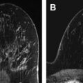
Using a dedicated breast coil, the patient is imaged prone with the breast compressed in a grid ( Fig. 1 A). A fiducial marker (visible on T1-weighted sequences) should be placed within the grid to facilitate lesion localization ( Fig. 1 B). Following a localizer sequence, T1-weighted fat-saturated sequences are obtained. A pregadolinium sequence is obtained to ensure the lesion will be located within the boundaries of the grid. Before gadolinium, it can be difficult to determine the location of a small lesion that is conspicuous only by its enhancement characteristics. In general, the approximate location of the lesion can be determined using regional landmarks; this may take a moment, as even the landmarks may have shifted substantially under grid compression relative to their position on the (noncompressed) diagnostic MRI. The pregadolinium sequence is also important to ensure good fat saturation and to serve as a mask for subtraction images.

Although multiple different MR imaging breast biopsy kits exist on the market (and the authors do not endorse any specific vendor), the basic components of the system are generally similar ( Fig. 2 A). Most biopsy kits consist of a coaxial system (including inner and outer components) and the needle guide. The outer component of the coaxial system is a plastic introducer sheath that is marked with numeric gradations and has a mobile “depth stop” on its surface (see later discussion) ( Fig. 2 B). There are 2 inner components that are used in succession: a (non-ferrous) metallic, cutting introducer stylet and a plastic obturator ( Fig. 2 A). The numeric gradations on the outer plastic introducer sheath allow the coaxial system to be inserted into the breast to a specified depth. This insertion is performed using the cutting introducer stylet as the inner component ( Fig. 2 B–D).

The function of the needle guide becomes clear when the guide is evaluated in profile. The guide is composed of multiple short tunnels ( Fig. 2 E). By inserting the coaxial system through 1 of these tunnels, the system is forced to remain parallel to the chest wall, adding an additional level of safety to the procedure. The guide fits within 1 of the squares of the grid, and the 3-component unit (coaxial introducer plastic sheath and stylet traversing 1 of the tunnels of the needle guide) represents the starting point of the biopsy ( Fig. 2 F). Alternatively, the guide can be placed into the grid by itself, and the coaxial system subsequently inserted.
The biopsy site is generally determined using a grid system (although other approaches exist), and computer localization software is often used. Multiple software options are available, and will work well provided the radiologist has familiarity with usage. Recall that the grid is composed of rows and columns of evenly sized and spaced squares ( Fig. 1 B). Localization software specifies the particular square to access within the grid, the particular hole (tunnel entry) within the needle guide, and the desired depth ( Fig. 3 ).

Lesions can also be localized manually, and even radiologists who generally use a software system should have an understanding of the principles of manual localization. Determining the access site (which square within the grid and which tunnel within the needle guide) is relatively straightforward: compare the location of the lesion with the known fiducial position or with a chosen landmark square. The depth to which the needle should be inserted can be calculated. The skin surface is considered to be the slice where the hypointense grid indentations are best seen. By counting the number of sagittal slices from the skin surface to the lesion, and multiplying this number by the slice thickness, the depth of the lesion is determined. If localizing in this manner, the thickness of the needle block (2 cm) also needs to be added.
Once the necessary coordinates (grid square, needle guide tunnel, and insertion depth) are provided by the software or determined by manual calculation, take a moment to ensure that the target location can be safely accessed. For example, ensure that the sampling trough will be clear of skin and pectoralis muscle. Skin sampling can require stitch closure, and pectoralis biopsy can be exquisitely painful and may lead to substantial hematoma formation.
The skin surface of the breast beneath the target square of the grid is then cleaned, and local anesthetic administered. Once anesthetized, a scalpel is used to incise the skin. The introducer stylet’s cutting tip is sharp enough to puncture the skin surface, but this is indeed a puncture rather than a clean incision. Once the skin is incised, the 3-component unit ( Fig. 2 F) is inserted: the needle guide is inserted firmly into the grid square, and the coaxial system is advanced through the needle guide into the breast. The inner cutting stylet is used to penetrate tissues and place the device at the target depth. This inner stylet is then removed while the outer plastic sheath maintains the position of the system in the breast. The plastic obturator ( Fig. 2 A) is placed within the sheath and an image is obtained to ensure appropriate position. Necessary adjustments in position should then be made. If the coaxial system needs to be advanced deeper into the breast, the introducer stylet should be reinserted. If the system needs to be retracted, this can be done with the obturator in place. Once in good position, the obturator should be removed and replaced with the handheld vacuum-assisted biopsy device. The biopsy is then performed using directional sampling, which is described in detail later. Twelve samples are typically obtained.
After the biopsy samples have been obtained, the cavity should be lavaged and aspirated. By minimizing hyperintense blood in the biopsy cavity, lavage and aspiration assist in the evaluation of sampling adequacy. In addition, aspiration decreases hematoma, increasing patient comfort and helping to minimize marker displacement. After lavage and aspiration, the obturator should be replaced into the sheath and a postbiopsy sequence obtained. This sequence is important because the radiologist needs to evaluate the adequacy of the biopsy. If the target lesion is smaller or no longer visualized on the postbiopsy sequence, the proceduralist can be more confident in the success of the procedure. If the lesion appears unchanged, additional samples should be obtained. In addition, if a developing hematoma is seen on the postbiopsy sequence, additional aspiration may be used for further evacuation. In the case of rapidly developing hematoma, consider placing a localizing marker immediately (see later discussion), and promptly removing the patient from the scanner to apply pressure to the biopsy site.
Once sampling is completed, an MRI-compatible localizing marker should be deployed. Whether an additional sequence is needed after marker deployment is controversial. Procedure-related changes may obscure the sampling bed and prevent visualization of the marker (or, more precisely, prevent visualization of susceptibility artifact from the marker).
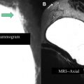
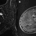
At this point, the patient is removed from the biopsy table. The breast is compressed to achieve hemostasis. After a rest period, the patient is transferred to the mammography suite where a postbiopsy mammogram is obtained. Careful comparison is made of the marker position on the mammogram with the expected location of the lesion based on the diagnostic and pre-biopsy MRI ( Fig. 4 ). Any marker displacement (or suspicion thereof) needs to be clearly documented in the report. For the patient, the procedure is then complete. For the radiologist, the procedure should only be considered truly complete once pathology has returned and concordance is assessed.
Fundamentals
Technically detailed articles on performing MRI–guided biopsy have existed in the literature for at least a decade. In 2003, Liberman and colleagues described their early experiences with vacuum-assisted MR imaging–guided biopsy. Their article remains an excellent review of the recommended technique.
Using a dedicated breast coil, the patient is imaged prone with the breast compressed in a grid ( Fig. 1 A). A fiducial marker (visible on T1-weighted sequences) should be placed within the grid to facilitate lesion localization ( Fig. 1 B). Following a localizer sequence, T1-weighted fat-saturated sequences are obtained. A pregadolinium sequence is obtained to ensure the lesion will be located within the boundaries of the grid. Before gadolinium, it can be difficult to determine the location of a small lesion that is conspicuous only by its enhancement characteristics. In general, the approximate location of the lesion can be determined using regional landmarks; this may take a moment, as even the landmarks may have shifted substantially under grid compression relative to their position on the (noncompressed) diagnostic MRI. The pregadolinium sequence is also important to ensure good fat saturation and to serve as a mask for subtraction images.
Although multiple different MR imaging breast biopsy kits exist on the market (and the authors do not endorse any specific vendor), the basic components of the system are generally similar ( Fig. 2 A). Most biopsy kits consist of a coaxial system (including inner and outer components) and the needle guide. The outer component of the coaxial system is a plastic introducer sheath that is marked with numeric gradations and has a mobile “depth stop” on its surface (see later discussion) ( Fig. 2 B). There are 2 inner components that are used in succession: a (non-ferrous) metallic, cutting introducer stylet and a plastic obturator ( Fig. 2 A). The numeric gradations on the outer plastic introducer sheath allow the coaxial system to be inserted into the breast to a specified depth. This insertion is performed using the cutting introducer stylet as the inner component ( Fig. 2 B–D).
Related posts:
 Breast Magnetic Resonance Imaging Technique at 1.5 T and 3 T
 Updates and Revisions to the BI-RADS Magnetic Resonance Imaging Lexicon
Screening MR Imaging Versus Screening Ultrasound
BI-RADS 3 for Magnetic Resonance Imaging
Updates and Revisions to the BI-RADS Magnetic Resonance Imaging Lexicon
Screening MR Imaging Versus Screening Ultrasound
BI-RADS 3 for Magnetic Resonance Imaging
 Evaluation of Breast Silicone Implants
 Radiologic-pathologic Correlation at Breast MR Imaging
Stay updated, free articles. Join our Telegram channel

Full access? Get Clinical Tree


