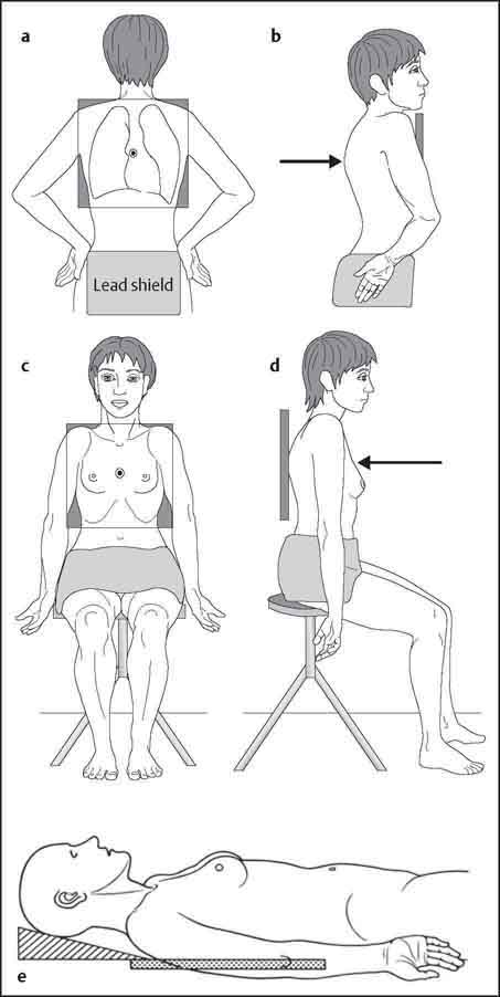
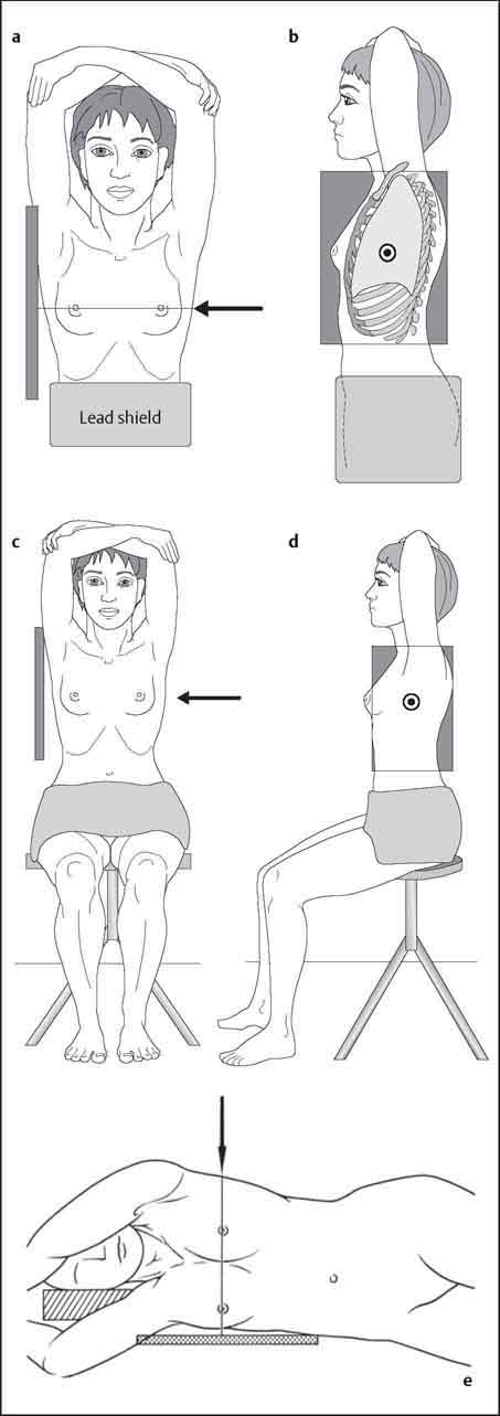
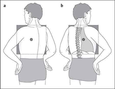
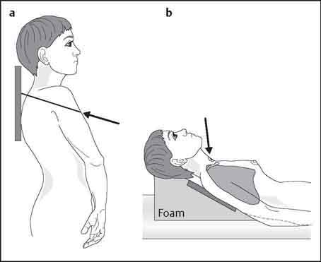
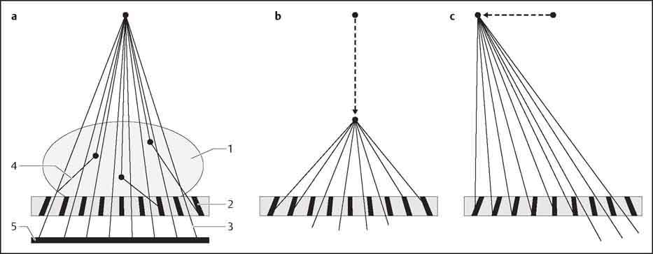
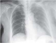
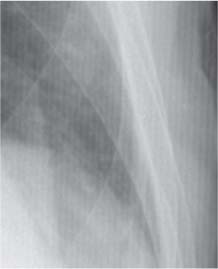
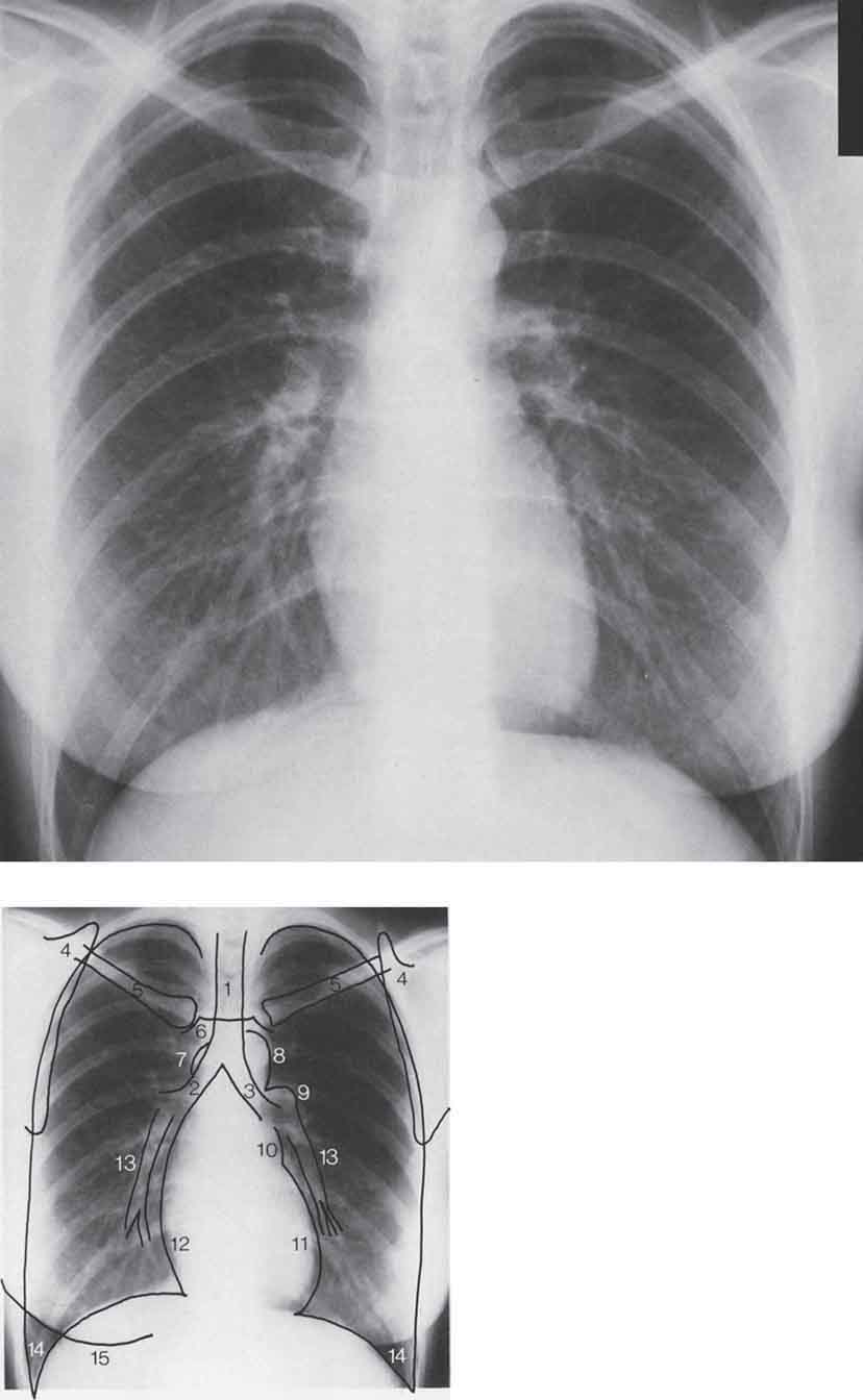
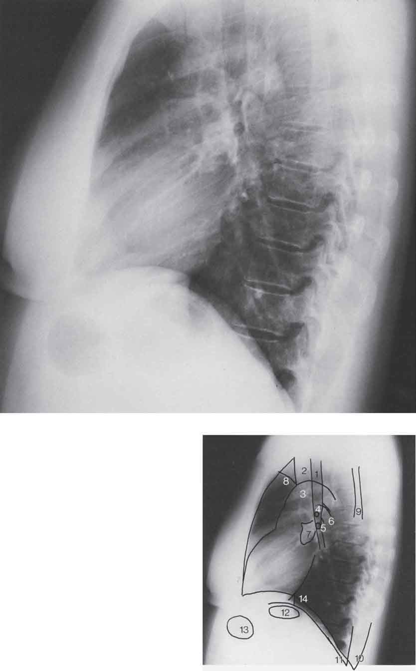
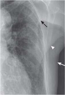
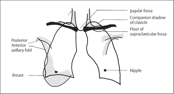
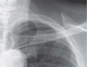
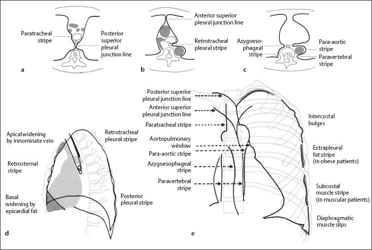
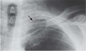
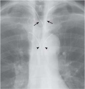
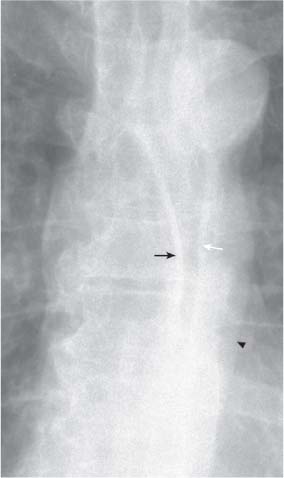
1 Examination Technique and Normal Findings Indication and radiation exposure: All radiographic examinations should be medically indicated, and stricter criteria should be applied in selecting patients for thoracic CT—which gives a radiation dose in the range of 6–10 mSv—than for standard chest radiographs where the dosage is much lower at 0.02–0.05 mSv. In addition, the risk of side effects from contrast agents used in CT, angiography, radionuclide imaging, and magnetic resonance imaging (MRI) should always be weighed against the expected gain in diagnostic information. Use of imaging studies: The frontal posteroanterior (PA) and lateral chest radiographs constitute the basic radiologic examination of the thorax. Radiographs should be acquired at full inspiration in the upright position, although in sick or debilitated patients supine or semisupine anteroposterior (AP) views at functional residual capacity may be the only option. Plain radiographic findings together with the presumptive clinical diagnosis will determine the need for further imaging studies. In current clinical practice, the most commonly requested second-line imaging investigations are CT, ventilation-perfusion scintigraphy (VQS), and ultrasound. Magnetic resonance imaging increasingly is being used in cardiac/myocardial assessment, and angiography continues to play a role in diagnosis as well as intervention. Reading: Meticulous image interpretation is important. The “five D’s” provide an effective strategy for reading all thoracic imaging procedures: detect, describe, discuss, differential diagnosis, and decide. Detect: A methodical approach is important in image interpretation. In evaluation of the chest radiograph, the heart size, shape and contour, mediastinal/hilar contour and widening/size, the lungs, pleura, bony and soft tissue structures of the chest wall should be systematically assessed. Review areas include the apices, costophrenic angles, retrocardiac lung, and posterior mediastinum. Describe and Discuss: If a pulmonary abnormality is detected, it may be assigned to one of the radiographic patterns in Chapter 13. Differential diagnosis: Good results have been achieved with the “gamut approach” (Reeder and Felson 2003). Just as a musician deliberately strikes each note while practicing scales on a piano, every possible interpretation of a pattern should be considered when reading an image. At the very least, the reader should consider the various main disease categories. These include congenital malformations, inflammatory disorders, chronic obstructive pulmonary disease (COPD), inhalational diseases and pneumoconioses, neoplasia, vascular disorders, and trauma. Decide: The ultimate goal of imaging is to make a definitive diagnosis. The clinical data frequently are important in making a definitive diagnosis. Sometimes, however, this is not possible and the radiologist can do no more than offer a differential diagnosis in which diagnoses are listed in order of probability. In this case cytology/histology may be required to make a definitive diagnosis. The upright patient positions his anterior chest against the film cassette (Fig. 1.1a, b). The dorsal aspects of the hands are placed on the hips, and the shoulders are rolled forward to project the scapulae outside the lungs. For better support, weak patients may place their arms around the cassette stand. Fig. 1.1a–e Chest radiographs in PA and AP projections. a, b Standing PA radiograph. c, d Sitting AP radiograph. e Supine AP radiograph. The patient wears a short lead apron. The upper border of the cassette is at the level of C7, and 35 × 35 to 40 × 40 cm size film is used, depending on patient size. The roentgen beam is collimated laterally on the skin surface over the lower ribs and is centered on the fourth thoracic vertebra (T4). The radiograph is taken at full inspiration using, for example, a film-focus distance (FFD) of 185 cm and exposure parameters of approximately 125 kV, 5 mA, or automatic exposure control. The AP projection is useful for imaging sick patients (Fig. 1.1c, d). Bedridden patients are filmed in the supine position, and internal rotation of the shoulders aids in separating the scapulae (Fig. 1.1e). The technical parameters recommended for chest radiographs are listed in Table 1.1. Table 1.1 Technical parameters for chest radiographs (Zimmer and Zimmer-Brossy 1992) The patient, wearing a lead apron, stands sideways against the cassette with arms raised. The roentgen beam is centered approximately 10 cm caudal to the axilla (Fig. 1.2a, b). The radiograph is taken at full inspiration using film size 30 × 40 or 35 × 35 cm. A FFD of 185 cm and settings of 125 kV, approximately 8 mA, or automatic exposure control are appropriate. Debilitated patients are radiographed in the sitting position (Fig. 1.2c, d) or, if necessary, in the lateral decubitus position with the head supported, the arms drawn forward and upward, and the legs slightly flexed to improve stability (Fig. 1.2e). Fig. 1.2a–e Lateral chest radiographs. a, b Standing lateral radiograph. c, d Sitting lateral radiograph. e Supine lateral radiograph. The patient is rotated in the frontal plane to approximately 45° with either the right (right anterior oblique or “fencer” position; Fig. 1.3a) or left anterior chest wall (left anterior oblique or “boxer” position; Fig. 1.3b) in contact with the cassette. The depth of inspiration, film size, FFD, and exposure parameters are the same as for the PA view. Fig. 1.3a, b Oblique chest radiographs. a Right anterior oblique (fencer) position, b left anterior oblique (boxer) position. The patient stands about 4 cm from the chest stand and arches the upper body backward until the shoulders touch the cassette. A FFD of 100 cm and 35–45° of cephalad tube angulation are appropriate. The beam is centered on the manubrium sterni (Fig. 1.4). A technically acceptable image shows the lung apices projected clear of the scapulae. Fig. 1.4a, b Apical lordotic views. a Standing, b supine. Fluoroscopy is used occasionally today and is a valuable adjunct to the chest radiograph. It analyzes dynamic processes and facilitates localization of pathologic changes but it has a much lower spatial resolution than the chest radiograph. Fluoroscopy is performed using an AP or PA beam at maximum shutter aperture. This permits comparison of the respiratory movements of the diaphragm and chest wall on both sides. The patient should breathe deeply, cough, blow his nose, and expire against a closed glottis to raise intrathoracic pressure (Valsalva maneuver). Finally, the patient attempts to inhale with the nostrils pinched shut; this lowers intrathoracic pressure (Müller maneuver). Sniffing is important since it elicits pure diaphragmatic motion and can thus magnify any asymmetric or paradoxical motion. The above-described supplementary chest views together with fluoroscopy are used less frequently as CT becomes the mainstream second line imaging investigation in the assessment of thoracic disease. Grids are used to reduce scatter radiation, which degrades contrast in radiographic images. Two main types are available: Focused moving grids, which are used on a Bucky table. The strips in the grid are aligned to match the divergence of the primary beam (Fig. 1.5a). Because the grid moves during the exposure, grid lines do not appear in the final image. There are two main sources of exposure errors with this type of grid system: Fig. 1.5a–c Scatter-reduction grids. The strips of the grid converge toward the roentgen focus (a). A defocused grid (b) leads to underexposure of the lateral areas. An off-center grid (c) leads to asymmetrical exposure (modified from Laubenberger 1980). Fig. 1.6 Asymmetrical exposure due to a tilted grid. Note the decreased lucency of the lung and “haziness” of the bones and soft tissues on the left side. Fig. 1.7 Stationary grid for bedside radiography. Vertical grid lines are visible on the image. Stationary grids with parallel strips are used for bedside radiography. Often it is difficult to position the patient as desired, and it is not unusual to work with a tilted grid. This also causes asymmetrical film exposure because the strips at one edge are aligned with the beam divergence while the strips at the other edge are not (Fig. 1.7). When an image made with a stationary grid is examined closely (e. g., with a magnifying lens), grid lines always can be seen. The chest radiograph requires a systematic evaluation (Figs. 1.8 and 1.9) in which the are identified, analyzed, and described. To reinforce this approach, these regions will be considered in the above order. The thoracic skeleton comprises the ribs, vertebral column, scapulae, clavicles, and sternum. The posterior aspects of the ribs have an almost horizontal orientation, and they then extend obliquely forward from superolateral to inferomedial to the costochondral junction. Rib cartilages are not visible on chest radiographs except in the elderly when cartilage calcification may be present. The dorsal aspects of the ribs appear denser because they have an almost circular anatomic cross section, while the ventral aspects are flatter and therefore more radiolucent. The ribs may have a slightly ill-defined inferior border due to thinning of the bone at the subcostal sulcus. Fig. 1.8 PA chest radiograph. 1 Trachea 2 Right main bronchus 3 Left main bronchus 4 Scapula 5 Clavicle 6 Manubrium sternum 7 Azygos vein 8 Aortic arch 9 Left pulmonary artery 10 Upper left cardiac border, left atrial appendage 11 Lower left cardiac border, left ventricle 12 Right atrium 13 Lower lobe arteries 14 Lateral costophrenic angle 15 Breast shadow Fig. 1.9 Lateral chest radiograph. 1 Trachea 2 Pretracheal vascular bundle 3 Aortic arch 4 Right upper lobe bronchus 5 Left upper lobe bronchus 6 Left pulmonary artery 7 Right pulmonary artery in pretracheal vascular oval 8 Axillary fold 9 Scapula 10 Right posterior costophrenic angle (right hemidiaphragm visible as far as the sternum) 11 Left posterior costophrenic angle (left hemidiaphragm visible as far as the cardiac silhouette) 12 Gastric bubble 13 Transverse colon 14 Inferior vena cava The vertebral column should be visible through the cardiac silhouette on a well-exposed frontal radiograph. The vertebral bodies, pedicles, spinous and transverse processes may be identified. On the lateral view, the superior and inferior articular processes may be identified. The medial and lateral borders, the inferior angle, the spine, and the coracoid process of the scapula may be identified on the frontal chest radiograph. On the lateral view, the scapulae project onto the vertebral column as dense vertical bands; their connection with the raised upper arms usually can be appreciated. The clavicles extend horizontally from the acromioclavicular joints laterally to the sternoclavicular joints medially. They are projected over the lung apices on the frontal radiograph. A notch formed by the insertion of the costoclavicular ligament often is seen inferiorly at the sternal end of the clavicle (rhomboid fossa). On the frontal radiograph, only the manubrium, part of the body of the sternum, and the sternoclavicular articulations are delineated. The lateral view defines the cortical outlines and the synchondrosis between the manubrium and body (Louis’ angle). The normal sternum shows a slight degree of anterior convexity. In the “funnel chest” deformity (pectus excavatum), the sternum is convex posteriorly and projects behind the anterior rib margins. In “pigeon chest” (pectus carinatum), the sternum is bowed forward, showing an exaggerated anterior convexity. The soft tissues form the contour of the chest wall. They also may project over the intrathoracic organs as opacities and interface lines (Figs. 1.10 and 1.11). Skin folds are especially prominent on supine radiographs of cachectic patients. They may form linear opacities and should not be mistaken for a pneumothorax. The breast shadows decrease the lucency of the lower lung zones. Nipple shadows may mimic small pulmonary nodules and may be quite asymmetrical in appearance. Fig. 1.10 Axillary folds: posterior axillary fold (white arrow), anterior axillary fold (arrowhead), apex of axilla (black arrow). Fig. 1.11 Soft-tissue shadows of the chest wall. The anterior and posterior axillary folds have caudally concave contours, and their interface may project over the lung, occasionally mimicking a pneumothorax. A third caudally concave shadow representing the apex of the axilla sometimes may be seen in thin patients. This narrow soft-tissue stripe along the upper border of the clavicle represents soft tissue that is tangential to the x-ray beam (Fig. 1.12). Fig. 1.12 Companion shadow of the clavicle (tangential projection of the skin over the clavicle) and the vertical shadow of the sternocleidomastoid muscle. The sternocleidomastoid muscle appears as an almost vertical soft-tissue opacity in the neck. It has a well-defined lateral border, and it merges inferiorly with the companion shadow of the clavicle. Visible only in thin patients, the supraclavicular fossa appears as a thin horizontal line projected above or below the clavicle. It extends laterally beyond the lung, thus distinguishing it from an apical pneumothorax (see Fig. 1.11). In thin patients, both sternocleidomastoid muscles have sharp medial borders and their contours unite inferiorly in a U-shaped configuration. This may sometimes mimic widening of the trachea. The lateral radiograph projects the soft tissues of the upper arm over the anteroapical lung. Usually the left and right upper arms can both be seen and their contours are continuous with the posterior axillary fold. The diaphragm forms the inferior boundary of the thorax. It is slightly curved towards the lung. In normal individuals, the angle between the chest wall and diaphragm is acute in inspiration. These angles border on the lung, so they are clearly visible laterally in the PA view and posteriorly in the lateral view (lateral and posterior costophrenic angles). The angle between the diaphragm and heart (cardiophrenic angle) is usually acute. In deep inspiration, the diaphragm moves sufficiently caudad to allow visibility of the 10th rib in the right cardiophrenic angle. During expiration, the dome of the diaphragm moves upward by approximately 3–7 cm. The right hemidiaphragm may lie up to 4 cm cranial to the left hemidiaphragm. The caudal surface of the diaphragm is not visible unless it is outlined on the left by the gastric bubble or on the right by air between the liver and diaphragm, as can occur in both pneumoperitoneum and colonic interposition (Chilaiditi syndrome). Individual muscle slips may give the smooth contour of the diaphragm a scalloped or serrated appearance in the lateral costophrenic angle. This normal variant may be especially pronounced in emphysema. If the distance between the lower border of the lung and the gastric air bubble is more than 1 cm, a pathologic process such as a subpulmonic effusion should be suspected. This sign is especially valuable in the lateral projection. Several features can be used to differentiate the left and right hemidiaphragms. On the lateral chest radiograph, the left hemidiaphragm is usually lower anteriorly and higher posteriorly with the gastric bubble lying inferiorly. Its contour extends anteriorly only to the posterior border of the cardiac silhouette. The right hemidiaphragm is usually higher anteriorly and lower posteriorly. Its contour may be traced throughout its posteroanterior course from the posterior costophrenic angle forward to the sternum (Fig. 1.13). The pleura consist of two layers. The parietal pleura lines the chest cavity and is fused with the chest wall, diaphragm, and mediastinum. The visceral pleura invests the surface of the lung and merges with the parietal pleura at the hilum. A capillary space containing a film of fluid permits relative motion between the two layers. Negative pressure is important in keeping the lungs inflated. Serum inflow would tend to equalize this pressure were it not for the low protein content of the pleural fluid and the oncotic “suction” of the adjacent capillary blood, which tends to draw fluid from the pleural space. Negative pressure is maintained even though approximately 100 mL of fluid flows from the parietal pleura to the visceral pleura each day. This is possible because of the unequal hydrostatic pressures in the chest wall and pulmonary capillaries (Fig. 1.14). Fig. 1.13 Radiographic appearance of the diaphragm. Fig. 1.14 Hydrostatic and oncotic pressure in the pleural layers (from Müller and Fraser 2001). The peripulmonary pleura invests the surface of the lung, and the interlobar pleura lines the fissures between the lobes. Radiographically, the peripulmonary pleura appears only as an interface between the lung and soft tissues. The interlobar pleura which comprises the fissures, on the other hand, often is directly visible as a hairline shadow. A dense stripe 0.5 mm in width may occasionally be seen in the area where the lung abuts the chest wall, diaphragm, and mediastinum. This stripe does not represent the pleura; it is a visual artifact caused by the collateral inhibition or stimulation of retinal receptors (Mach effect; Fig. 1.15). This is easily confirmed by covering the lung with a piece of paper next to the stripe and noting that the stripe is gone (Fig. 1.16). The peripulmonary pleura has several radiographically distinct components (Coussement and Butori 1978; Fig. 1.17). The apical pleura appears in profile as a stripe, 2 mm in width, at the inferior border of the posterior aspect of the second rib (Fig. 1.18). The pleural line, if seen tangentially, usually is smooth but occasionally bulges into the intercostal spaces, creating a scalloped contour. In obese patients an extrapleural fat stripe, several millimeters in width, may be visible between the inner surface of the ribs and the lung edge; this should not be confused with pleural thickening or a small pleural effusion. Occasionally the subcostal muscle fibers elevate the pleura, producing a wavy contour (see Fig. 1.16). Fig. 1.15a–c The Mach effect. The contour of the aorta on a chest radiograph (a) appears to be accompanied by a dark stripe (arrow), and the paravertebral space appears to be bounded by a bright stripe (arrowhead). These are optical illusions due to accentuation of contrast in the human retina. When two homogeneous areas of different brightness are apposed (1 in c), the actual densitometric profile (top row in c) is not perceived. Instead, the bright area appears even brighter while the dark area appears somewhat darker (bottom row in c). If the bright area darkens toward the boundary, the contrast appears to be accentuated only in the dark area (2 in b and c). If the dark area gradually lightens toward the boundary, a bright edge will be perceived (3 in b and c). A line may be seen passing medially and horizontally from the deepest point of the lateral costophrenic angle. This is seen particularly well on overexposed radiographs. It corresponds to the pleural reflection at the posterior costophrenic angle. Anteriorly the lung extends to the level of the clavicle, but posteriorly it projects more superiorly. On the lateral view, the soft-tissue shadow of the upper arm usually is superimposed usually on the lung apex. However, if the shoulders are lowered, the lung apex with its accompanying pleural shadow may be seen. On the lateral view, the posterior pleural stripe is visible in profile along the posterior ribs. The pleural stripe extends inferiorly to the posterior costophrenic angle and the diaphragmatic reflection. On the lateral view, the pleural line can help in identifying right and left diaphragmatic leaflets (see Fig. 1.13). Fig. 1.16 An apparent bright stripe is perceived at the boundary between the lung and soft tissue as a result of the Mach effect (see Fig. 1.15). Fig. 1.17a–e Pleural reflections (from Heitzman 1993, Meschan 1981). Fig. 1.18 The companion shadow of the second rib corresponds to the lung apex or the boundary between air and soft tissue. The catheter position defines the course of the subclavian vein. On the lateral view, the retrosternal stripe is relatively wide superiorly behind the manubrium. Here, the brachiocephalic vein is interposed between the lung and sternum. The stripe is narrower in its midportion, where the right and left anterior lung borders may be differentiated. The right pleura protrudes into the intercostal spaces and thus has a wavy contour; it is frequently projected over the body of the sternum. The left anterior pleural border is smoother because of the interposed heart. In the basal part of the retrosternal stripe, epicardial fat frequently displaces the left anterior lung border from the chest wall, producing a triangular retrosternal opacity (cardiac incisure). The pleura sweeps medially from both sides as a continuation of the companion shadow of the 2nd rib, unites at the level of the T3/4 intervertebral space, then passes as a vertical stripe to the aortic arch. This creates a Y-shaped shadow that corresponds to the posterior pleural reflection (see Figs. 1.17d, 1.19). It is composed of four layers of pleura and corresponds to the course of the superior intercostal veins. This pleural reflection corresponds to the course of the innominate and subclavian veins. It forms a Y-shaped configuration, the limbs of which originate from the inferior margins of the sternoclavicular joints. They course caudally, medially, and, on uniting, slant to the left. The anterior junction line complex extends inferiorly to the heart and encompasses the potential space of the anterior mediastinum (see Figs. 1.17e, 1.19). The right lung extends in front of the vertebral column and forms the azygoesophageal recess. It borders the azygos vein and the esophagus and forms a mediastinal pleural stripe in a paramedian location, paralleling the course of the esophagus (see Figs. 1.17e, 1.20). The posterior parts of the lungs are contiguous to the lateral aspects of the vertebral bodies. Pleura seen in tangent to the roentgen beam in this region forms a visible stripe on the left side. On the right side, the stripe is seen only if it is widened by aging or pathologic processes such as degenerative osteophyte formation, hematoma, or tumor (see Figs. 1.15a, 1.17e). On the left side, the paravertebral stripe can reach a width equal to half the diameter of the descending aorta. This accompanies the descending aorta on the left side. Comparison of the paravertebral and para-aortic stripes reveals an interesting visual phenomenon: The aortic border to the lung is a convex arch; this produces a negative Mach effect, resulting in an apparently darker stripe paralleling the descending aorta. The paravertebral soft tissues have a concave boundary with the lung; this results in a positive Mach effect creating the impression of a white border stripe (Figs. 1.15a, 1.17e, 1.20). This corresponds to the mediastinal pleural reflection on the tracheal wall. The inferior widening of the stripe is due to the horizontally orientated arch of the azygos vein. The width of the paratracheal stripe should not exceed 4mm. It frequently is superimposed on the superior vena cava. A well-exposed view, conventional or computed tomography (CT) will demonstrate the paratracheal stripe, azygos vein, and superior vena cava and will determine the true width of this stripe (see Fig. 1.17e). On the lateral radiograph, this stripe blends with the posterior border of the trachea and should not exceed 3 mm in width (see Fig. 1.17d). Fig. 1.19 The posterior pleural reflection (= posterior superior pleural junction line, arrows) and anterior pleural reflection (= anterior superior pleural junction line, arrowheads). Fig. 1.20
Radiographic Examination
Frontal Chest Radiograph
Technical specifications
Grid technique, wall cassette holder
Automatic exposure control:
• PA
Side chamber
• Lateral
Central chamber
Film format
40 × 40 (30 × 40, 35 × 35)
Film-screen system
Film speed 400 (200)
Focus-film distance
150–200 cm
Kilovoltage
110–150 kV
Exposure:
• PA
< 20 ms
• Lateral
< 40 ms
Scatter reduction grid
r/2(8)
Lateral Chest Radiograph
Oblique Views
Apical Lordotic View
Fluoroscopy
Scatter-Reduction Grids
The Normal Chest Radiograph
Structures of the Chest Wall
Thoracic Skeleton
Ribs
Vertebral Column
Scapula
Clavicles
Sternum
Soft Tissues of the Chest Wall
Skin Folds
Breast Shadow
Axillary Folds
Clavicular Companion Shadows
Sternocleidomastoid Muscle
Supraclavicular Fossa
Jugular Fossa
Upper Arms
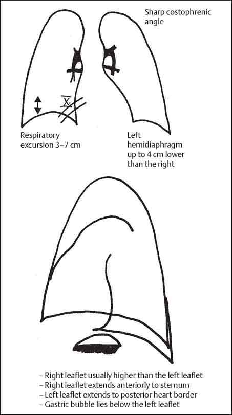
Diaphragm
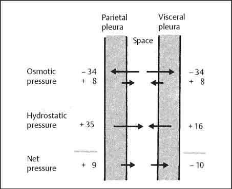
Pleura
Anatomy and Physiology
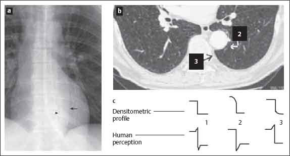
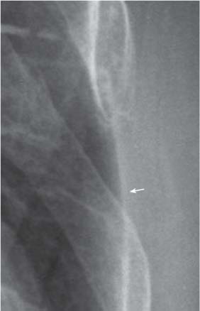
Radiographic Anatomy
Peripulmonary Pleura
Companion Shadow of the Second Rib
Companion Shadow of the Lateral Chest Wall
Basal Pleural Reflection
Apical Pleural Cap
Posterior Pleural Stripe
Retrosternal Stripe
Posterior Superior Pleural Junction Line
Anterior Superior Pleural Junction Line
Azygoesophageal Stripe
Paravertebral Stripe
Para-aortic Stripe
Right Paratracheal Stripe
Retrotracheal Stripe
![]()
Stay updated, free articles. Join our Telegram channel


Full access? Get Clinical Tree


