Exposure Technique Selection

Chapter 8


Exposure Technique Selection


The radiographer is responsible for selecting exposure factor techniques to produce quality radiographs for a wide variety of equipment and patients. There are many thousands of possible combinations of kVp, mA, SID, exposure time, image receptors (IRs), and grid ratios. When combined with patients of various sizes and with various pathologic conditions, the selection of proper exposure factors becomes a formidable task. Tools are available to assist the radiographer in selecting appropriate exposure techniques: automatic exposure control (AEC) devices, anatomically programmed radiography, and exposure technique charts. Knowledge about the performance of these tools and their operation assists the radiographer in producing quality radiographic images.


Automatic Exposure Control


An AEC system is a tool available on most modern radiographic units to assist the radiographer in determining the amount of radiation exposure to produce a quality image. Automatic exposure control (AEC) is a system used to control consistently the amount of radiation reaching the IR by terminating the length of exposure. AEC systems also are called automatic exposure devices, and sometimes they are erroneously referred to as phototiming. When using AEC systems, the radiographer must still use individual discretion to select an appropriate kVp, mA, IR, and grid. However, the AEC device determines the exposure time (and total exposure) that is used.


AEC systems are excellent at producing consistent levels of exposure when used properly, but the radiographer must also be aware of the limitations of using an AEC system in patient positioning and centering, detector size and selection, collimation, and IR variation.


Radiation Detectors


All AEC devices work by the same principle of operation: Radiation is transmitted through the patient and converted into an electrical signal, terminating the exposure time; this occurs when a predetermined amount of radiation has been detected, as indicated by the level of electrical signal that has been produced. The predetermined level of radiation that must be reached before exposure termination is calibrated by service personnel to meet the departmental standards of image quality.


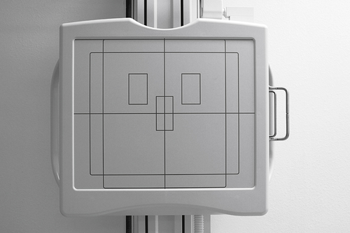
The difference in AEC systems lies in the type of device that is used to convert radiation into electricity. Two types of AEC systems have been used: phototimers and ionization chambers. Phototimers represent the first generation of AEC systems used in radiography, and it is from this type of system that the term phototiming has evolved. Phototiming specifically refers to the use of an AEC device that uses photomultiplier tubes or photodiodes, even though these systems are uncommon today. Therefore, the use of the term phototiming is usually incorrect. The more common type of AEC system uses ionization chambers. Regardless of the specific type of AEC system used, almost all systems use a set of three radiation-measuring detectors, arranged in some specific manner (Figure 8-1). The radiographer selects the configuration of these devices, determining which one (or more) of the three actually measures radiation exposure reaching the IR. These devices are variously referred to as sensors, chambers, cells, or detectors. These radiation-measuring devices are referred to here for the remainder of the discussion as detectors


Phototimers


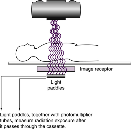
Phototimers use a fluorescent (light-producing) screen and a device that converts the light to electricity. A photomultiplier tube is an electronic device that converts visible light energy into electrical energy. A photodiode is a solid-state device that performs the same function. Phototimer AEC devices are considered exit-type devices because the detectors are positioned behind the IR (Figure 8-2) so that radiation must exit the IR before it is measured by the detectors. Light paddles, coated with a fluorescent material, serve as the detectors, and the radiation interacts with the paddles, producing visible light. This light is transmitted to remote photomultiplier tubes or photodiodes that convert this light into electricity. The timer is tripped, and the radiographic exposure is terminated when a sufficiently large charge has been received. This electrical charge is in proportion to the radiation to which the light paddles have been exposed. Phototimers have largely been replaced with ionization chamber systems.


Ionization Chamber Systems


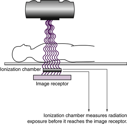
An ionization chamber, or ion chamber, is a hollow cell that contains air and is connected to the timer circuit via an electrical wire. Ionization chamber AEC devices are considered entrance-type devices because the detectors are positioned in front of the IR (Figure 8-3) so that radiation interacts with the detectors just before interacting with the IR. When the ionization chamber is exposed to radiation from a radiographic exposure, the air inside the chamber becomes ionized, creating an electrical charge. This charge travels along the wire to the timer circuit. The timer is tripped, and the radiographic exposure is terminated when a sufficiently large charge has been received. This electrical charge is in proportion to the radiation to which the ionization chamber has been exposed. Compared with phototimers, ion chambers are less sophisticated and less accurate, but they are less prone to failure. Most AEC systems today use ionization chambers.


mAs Readout


When a radiographic study is performed using an AEC device, the total amount of radiation (mAs) required to produce the appropriate exposure to the IR is determined by the system. Many radiographic units include an mAs readout display, where the actual amount of mAs used for that image is displayed immediately after the exposure, sometimes for only a few seconds. It is critical for the radiographer to take note of this information when it is available. Knowledge of the mAs readout has numerous advantages. It allows the radiographer to become more familiar with manual exposure technique factors. If the image is suboptimal, knowing the mAs readout provides a basis from which the radiographer can make exposure adjustments by switching to manual technique. There may be studies with different positions where AEC and manual technique are combined because of difficulty with accurate centering. For example, knowing the mAs readout for the anteroposterior (AP) lumbar spine gives the radiographer an option to switch to manual technique for the oblique exposures, making technique adjustments based on reliable mAs information.


kVp and mA Selections


AEC controls only the quantity of radiation reaching the IR and has no effect on other image characteristics, such as contrast. The kVp for a particular examination should be selected as it would be for that examination, regardless of whether an AEC device is used. The radiographer must select the kVp level that provides an appropriate level of contrast and is at least the minimum kVp to penetrate the part. Although in digital imaging contrast can be computer manipulated, the kVp should still be selected to visualize best the area of interest. In addition, the higher the kVp value used, the shorter the exposure time needed by the AEC device. Because high kVp radiation is more penetrating (reducing the total amount of x-ray exposure to the patient because more x-ray photons exit the patient) and the detectors are measuring quantity of radiation, the preset amount of radiation exposure is reached sooner with a high kVp.


When the radiographer uses a control panel that allows the mA and time to be set independently, he or she should select the mA value as it would be for that particular examination, regardless of whether an AEC device is used. The mA value selected will affect the exposure time needed by the AEC device. Therefore, if the radiographer wants to decrease exposure time for a particular examination, he or she may easily do so by increasing the mA value. For a given procedure, increasing the mA on the control panel decreases the exposure time, and decreasing the mA selected on the control panel increases the exposure time.


Minimum Response Time


The term minimum response time refers to the shortest exposure time that the system can produce. Minimum response time (1 ms with modern AEC systems) usually is longer with AEC systems than with other types of radiographic timers (i.e., other types of radiographic timers usually are able to produce shorter exposure times than AEC devices). This can be a problem with some segments of the patient population, such as pediatric patients and uncooperative patients. Typically, the radiographer increases the mA so that the time of exposure terminates more quickly. If the minimum response time is longer than the amount of time needed to terminate the preset exposure, it results in an increased amount of radiation reaching the IR. With pediatric patients and other patients who cannot or will not cooperate with the radiographer by holding still or holding their breath during the exposure, AEC devices may not be the technology of choice.


Backup Time


Backup time refers to the maximum length of time the x-ray exposure will continue when using an AEC system. The backup time may be set by the radiographer or controlled automatically by the radiographic unit. It may be set as backup exposure time or as backup mAs (the product of mA and exposure time). The backup time acts as a safety mechanism when an AEC system fails or the equipment is not used properly. In either case, the backup time protects the patient from receiving unnecessary exposure and protects the x-ray tube from reaching or exceeding its heat-loading capacity. If the backup time is controlled automatically, it should terminate at a maximum of 600 mAs.


The backup time might be reached as the result of operator oversight when an AEC examination, such as a chest x-ray, is done at the upright Bucky and the radiographer has set the control panel for table Bucky. The table detectors are forced to wait an excessively long time to measure enough radiation to terminate the exposure. The backup time is reached and the exposure is terminated, limiting the patient’s exposure and keeping the tube from overloading. However, newer x-ray units with AEC include a sensor in the Bucky tray for the IR and do not allow an exposure to activate if the table Bucky detectors were selected but the x-ray tube centered to the upright Bucky.


When controlled by the radiographer, the backup time should be set high enough to be greater than the exposure needed but low enough to protect the patient from excessive exposure in case of a problem. Setting the backup time at 150% of the expected exposure time is appropriate. If the backup timer periodically or routinely terminates the exposure, higher mA values should be used to shorten the exposure time.


Density Adjustment


AEC devices are equipped with density controls that allow the radiographer to adjust the amount of preset radiation detection values. These generally are in the form of buttons on the control panel that are numbered −2, −1, +1, and +2. The actual numbers presented on density controls vary, but each of these buttons changes exposure time by some predetermined amount or increment expressed as a percentage. A common increment is 25%, meaning that the predetermined exposure level needed to terminate the timer can be either increased or decreased from normal in one increment (+25% or −25%) or two increments (+50% or −50%). Manufacturers usually provide information for their equipment on how these density controls should be used. Common sense and practical experience should also serve as guidelines for the radiographer. Routinely using plus or minus density settings to produce an acceptable radiograph indicates that a problem exists, possibly a problem with the AEC device.


Alignment and Positioning Considerations


Detector Selection


Selection of the detectors to be used for a particular examination is critical when using an AEC system. AEC systems with multiple detectors typically allow the radiographer to select any combination of one, two, or all three detectors. The selected detectors actively measure radiation during exposure, and the electrical signals are averaged. Typically, the detector that receives the greatest amount of exposure has a greater impact on the total exposure.


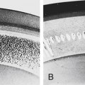
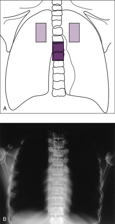
Measuring radiation that passes through the anatomic area of interest is important. The general guideline is to select the detectors that would be superimposed by the anatomic structures that are of greatest interest and need to be visualized on the radiograph. Failure to use the proper detectors could result in either underexposure or overexposure to the IR. In the case of a posteroanterior (PA) chest radiograph, the area of radiographic interest includes the lungs and heart; therefore, one or two outside detectors should be selected to place the detectors directly beneath the critical anatomic area. If the center detector were mistakenly selected, the anatomy superimposing this detector includes the thoracic spine. If the exposure is made, the resultant image shows sufficient exposure in the spine, with the lungs overexposed (Figure 8-4). In the manual that accompanies a radiographic unit, the AEC device manufacturer provides recommendations for which detectors to use for specific examinations. Recommendations for detector combination also can be found in many radiographic procedures textbooks.


Many radiographic units have AEC devices in both the table Bucky and an upright Bucky. If more than one Bucky per radiographic unit uses AEC, the radiographer must be certain to select the correct Bucky before making an exposure. Failure to do so may result in the patient and IR being exposed to excessive radiation. The backup time is reached, the exposure is terminated prematurely, and a repeat radiographic study may need to be done, increasing the patient’s dose.


A similar problem can occur in some systems when not using a Bucky, such as with cross-table, tabletop, or stretcher or wheelchair studies. If the AEC system is activated with these types of examinations, an unusually long exposure results because the detectors are not being exposed to radiation. Again, the backup time will likely be reached, and the patient’s dose will be excessive. Some radiographic units are designed so that an exposure does not occur if the AEC device has been selected and there is no IR detected in the Bucky.


Mar 6, 2016 | Posted by in GENERAL RADIOLOGY | Comments Off on Exposure Technique Selection

Full access? Get Clinical Tree

Get Clinical Tree app for offline access