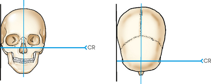
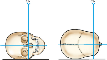
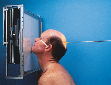
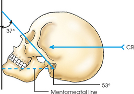
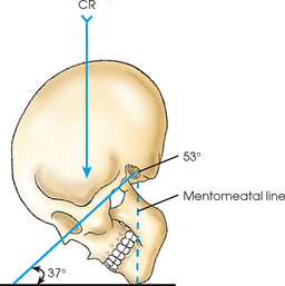
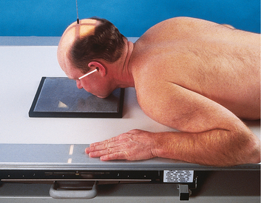
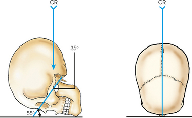
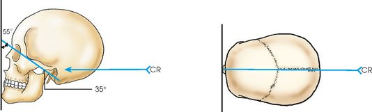
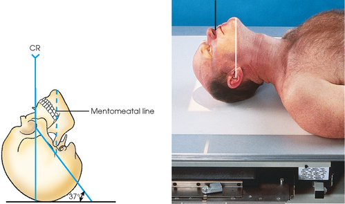
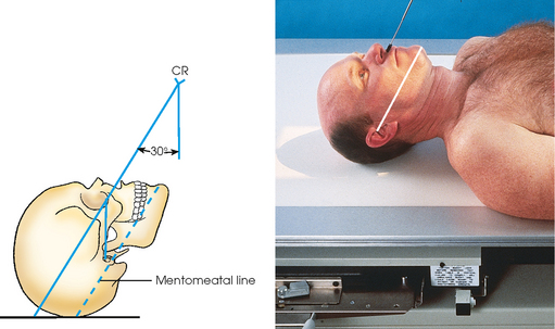
21 • Rest the patient’s head on the tip of the extended chin. Hyperextend the neck so that the orbitomeatal line (OML) forms a 37-degree angle with the plane of the IR. • The mentomeatal line (MML) is approximately perpendicular to the plane of the IR; the average patient’s nose is about ¾ inch (1.9 cm) away from the grid device. • Adjust the head so that the midsagittal plane is perpendicular to the plane of the IR (Figs. 21-5 to 21-7). • Center the IR at the level of the acanthion. Although the parietoacanthial projection (Waters method) is widely used, many institutions modify the projection by radiographing the patient using less extension of the patient’s neck. This modification, although sometimes called a “shallow” Waters, actually increases the angulation of the OML by placing it more perpendicular to the plane of the IR. The patient’s head is positioned as described using the Waters method, but the neck is extended a lesser amount. In the modification, the OML is adjusted to form an approximately 55-degree angle with the plane of the IR (Figs. 21-9 to 21-11). The resulting radiograph shows the facial bones with less axial angulation than with the Waters method (see Fig. 21-8). With the modified Waters method, the petrous ridges are projected immediately below the inferior border of the orbits at a level midway through the maxillary sinuses (Fig. 21-12). • Bringing the patient’s chin up, adjust the extension of the neck so that the OML forms a 37-degree angle with the plane of the IR (Fig. 21-13). If necessary, place a support under the patient’s shoulders to help extend the neck. • The MML is approximately perpendicular to the plane of the IR. • Adjust the patient’s head so that the midsagittal plane is perpendicular to the plane of the IR. Trauma patients are often unable to hyperextend the neck far enough to place the OML 37 degrees to the IR and the MML perpendicular to the plane of the IR. In these patients, the acanthioparietal projection, or the reverse Waters projection, can be achieved by adjusting the central ray so that it enters the acanthion while remaining parallel with the MML (Fig. 21-15). • Adjust the flexion of the patient’s neck so that the OML is perpendicular to the plane of the IR. • If the patient is obese or hypersthenic, a small radiolucent sponge may need to be placed in front of the forehead. • Align the midsagittal plane perpendicular to the IR by adjusting the lateral margins of the orbits or the EAM equidistant from the tabletop. • Immobilize the patient’s head, and center the IR to the nasion (Fig. 21-16). Structures shown: The PA axial projection, Caldwell method, shows the orbital rims, maxillae, nasal septum, zygomatic bones, and anterior nasal spine. When the central ray is angled 15 degrees caudad to the nasion, the petrous ridges are projected into the lower third of the orbits (Fig. 21-17). When the central ray is angled 30 degrees caudad, the petrous ridges are projected below the inferior margins of the orbits. • Adjust the head so that the midsagittal plane is parallel with the tabletop and the interpupillary line is perpendicular to the tabletop. • Adjust the flexion of the patient’s neck so that the IOML is parallel with the transverse axis of the IR (Figs. 21-18 and 21-19). • Support the mandible to prevent rotation. • When using an 8- × 10-inch (18- × 24-cm) IR, slide the unmasked half of the IR under the frontonasal region and center it to the nasion (see Fig. 21-18). This centering allows space for the identification marker to be projected across the upper part of the IR. Tape the side marker (R or L) in position.
FACIAL BONES*
Facial Bones
R or L position
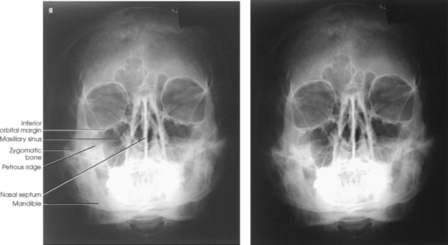
 PARIETOACANTHIAL PROJECTION
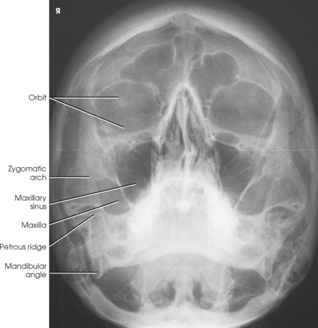
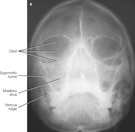
MODIFIED PARIETOACANTHIAL PROJECTION
 ACANTHIOPARIETAL PROJECTION
ACANTHIOPARIETAL PROJECTION FOR TRAUMA
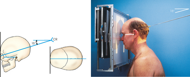
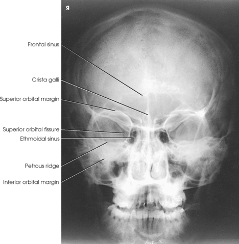
 PA AXIAL PROJECTION
Nasal Bones
R and L positions
Radiology Key
Fastest Radiology Insight Engine
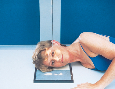
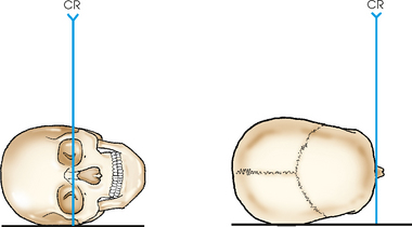
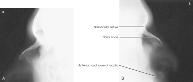
 LATERAL PROJECTION
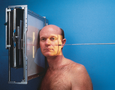
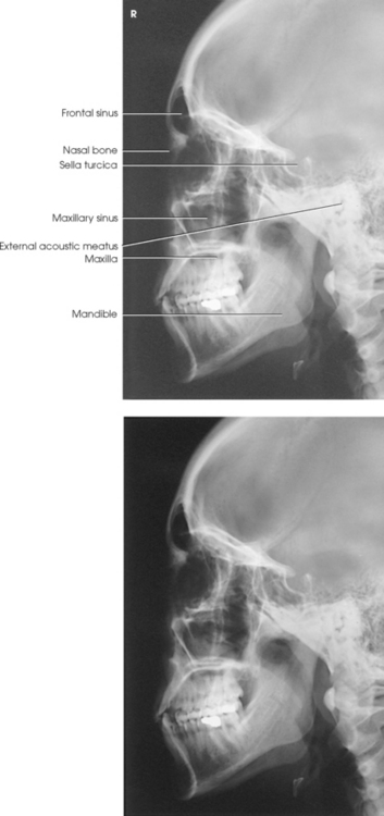


 LATERAL PROJECTION