Foot and Heel
Dominic Barron
K. Partington
John H. Harris Jr.
Thomas L. Pope Jr.
GENERAL CONSIDERATIONS
Anatomically, the foot includes all of the tarsal bones, the metatarsals, and the phalanges. The forefoot includes the metatarsals and the phalanges; the midfoot includes the three cuneiform bones, the cuboid, and the navicular bones; and the hindfoot includes the talus and calcaneus.
Injuries of the heel or midfoot commonly produce clinical signs suggesting an abnormality of the ankle, as discussed further in Chapter 21. Careful clinical evaluation is required to guide appropriate imaging of the injured area.
It is no longer routine standard of care to obtain the opposite side views in an injury involving the peripheral skeleton of a child or adolescent. Rather, the current standard is that radiographic studies of the opposite side should be obtained when specifically required to help distinguish between a developmental variant and a traumatic lesion, in the opinion of the radiologist.
Imaging Techniques
Routine radiographic study of the foot includes anteroposterior, internally rotated oblique, and lateral views (Fig. 22.1). The lateral is sometimes omitted but this does then make evaluation of subtle midfoot injuries difficult. Routine radiographs of the heel are the lateral and axial projections.1
Where additional information regarding the bony anatomy of these areas are required, computed tomography (CT) is indicated due to its volumetric acquisition, multiplanar reformations, and 3-D reconstructions.2
Magnetic resonance imaging (MRI) is becoming increasingly valuable in the assessment of the foot. The main indications are purely soft tissue injuries, stress reactions or fractures, infection, and the acute diabetic foot.
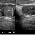
Ultrasound has a relatively limited role in this area due to predominance of bony problems. It is, however, excellent at assessment of Morton- neuroma- and plantar fascia- based pathologies.
RADIOGRAPHIC ANATOMY AND VARIANTS
In the foot, two sesamoid bones are normally present on the volar aspect of the head of the first metatarsal (Fig. 22.2). Either of these may be bifid developmentally. This variant may be distinguished from an acute fracture by the sclerotic, parallel margins of the separate ossification centers. When present, this variant is usually bilateral. Sesamoid bones are occasionally seen at the level of the interphalangeal joint of the great toe and the metatarsophalangeal joint of the second and little toes.
The tubercle of the tarsal navicular may constitute a separate bone (os tibiale externum) in approximately 4% of the population.3 Other variants that can be diagnostically perplexing include the os intermetatarseum, os peroneum (a sesamoid bone sometimes found in the peroneus longus tendon) and the talar “beak” (Fig. 22.3).
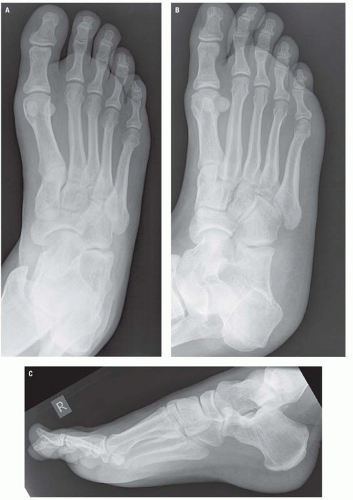 Figure 22.1. Routine radiographic examination of the foot. A: Frontal. B: Internally rotated oblique. C: Lateral. |
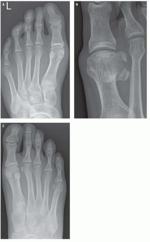 Figure 22.2. Sesamoids. A: AP view of tibial sesamoid. B: Acute fracture of both great toe sesamoids. C: Sesamoids to both the second and fifth toes. |
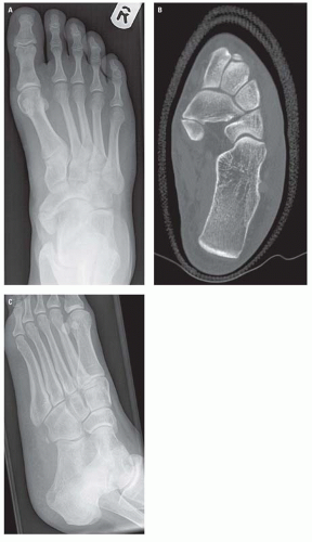 Figure 22.3. Os tibiale externum. A: AP radiograph of os tibiale externum. B: Axial CT view demonstrating the classical sclerotic smooth edges of accessory bone. C: Os peroneum. |
Normal osseous structures that can cause diagnostic difficulty in the foot include nutrient artery canals, the calcaneal apophysis, the cone epiphyses, and the normal orientation of the epiphyses.
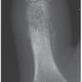
A nutrient artery canal should not be mistaken for an incomplete fracture or a stress fracture. The artery groove is oriented obliquely and distally in the midshaft of a metatarsal or, rarely, a proximal or middle phalanx. Its margins will be parallel, smooth, and faintly sclerotic. The nutrient canal is usually seen in only one projection, whereas the irregular, jagged margins of a fracture line should be evident in more than one projection (Fig. 22.4).
The calcaneal apophysis is typically fragmented and irregularly more dense than the calcaneus (Fig. 22.5). For a comprehensive review of normal variants that may simulate disease, the reader is referred to Keats and Anderson.4
Figure 22.1 is an anteroposterior view of the normal adult foot. The lateral cuneiform and cuboid are superimposed, and the anatomy of the bases of the lateral four metatarsals is obscure due to superimposition caused by the normal transverse arch of the midfoot. On this view, the lateral aspects of the first metatarsal and the medial cuneiform should align, as should the medial aspects of the second metatarsal and the intermediate cuneiform.
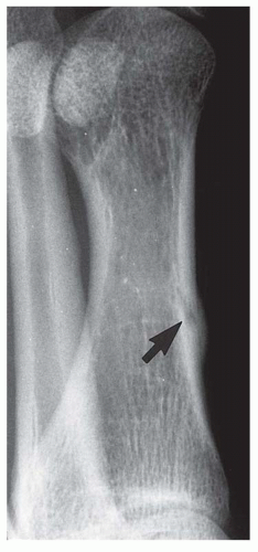 Figure 22.4. Nutrient artery canal (arrow). |
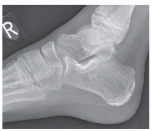 Figure 22.5. Calcaneal apophysis. Lateral view showing the typical sclerotic appearance to the calcaneal apophysis. |
The internally oblique view is made with the foot internally rotated and the central beam perpendicular to the tabletop centered over the third metatarsal; thus, the lateral cuneiform, cuboid, and lateral three metatarsals are projected into profile. On the internal oblique view, the medial aspects of the third metatarsal and third cuneiform should align. The lateral radiograph of the foot is essential in the radiographic evaluation of the heel and midfoot. The subtalar, talonavicular, and calcaneocuboid joints are seen well in this projection.
The externally rotated oblique projection is designed to project the medial cortical surface of the navicular, the first cuneiform, and the base of the first metatarsal in profile. This is usually omitted from the standard series and is reserved for cases where there is specific concern for injuries to this area.
The axial projection of the os calcis demonstrates the convex lateral and concave medial surfaces of the calcaneus and, in an adequately exposed radiograph, provides a clear view of the sustentaculum talus. The lateral radiograph of the heel demonstrates the subtalar joint, the sustentaculum tali, the anterior tubercle of the os calcis, and the calcaneocuboid joint (Fig. 22.6).5
Figure 22.7 is of a normal child’s foot, where the epiphyses of the lateral four metatarsals are distally
located. Those of the first metatarsal and all of the phalanges are proximally situated. Cone epiphysis is another classical pitfall (Fig. 22.8).
located. Those of the first metatarsal and all of the phalanges are proximally situated. Cone epiphysis is another classical pitfall (Fig. 22.8).
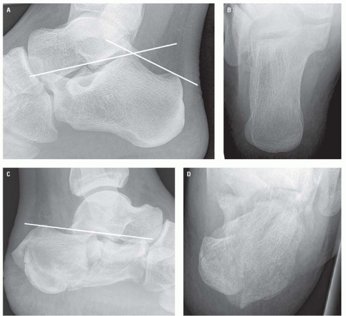 Figure 22.6. A: Normal lateral view of the calcaneus with normal Bohler angle. B: Normal axial view of the calcaneus. C: Complete loss of Bohler angle secondary to multisegmental intra-articular calcaneal fracture. D: Axial view of the same fracture. |
In addition to looking for cortical disruptions and misalignment, Bohler angle should routinely be measured when assessing for calcaneal injuries. This angle is formed by the intersection of lines drawn tangentially to the anterior and posterior elements of the superior surface of the calcaneus. The normal range is between 20 and 40 degrees, with the normal average between 30 and 35 degrees (Fig. 22.6).6
RADIOGRAPHIC MANIFESTATIONS OF TRAUMA
Talar Injuries
The talar subluxations and dislocations usually involve the ankle mortise in association with ankle fracture dislocations and are fully described in Chapter 21.
Dislocation of the talus with respect to the ankle mortise without an associated fracture7 and “peritalar”8
and “subtalar”9, 10, 11 dislocation—both terms for concomitant dislocation at the subtalar and talonavicular joints with a normal tibiotalar relationship—are rare. However, these can easily be overlooked, and careful evaluation of the ankle series should always include an assessment of the subtalar joint.
and “subtalar”9, 10, 11 dislocation—both terms for concomitant dislocation at the subtalar and talonavicular joints with a normal tibiotalar relationship—are rare. However, these can easily be overlooked, and careful evaluation of the ankle series should always include an assessment of the subtalar joint.
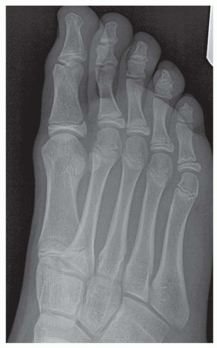 Figure 22.7. DP oblique view of child’s foot showing the multiple physeal lines. |
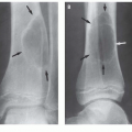
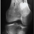
Talar dome (transcondylar, osteocartilaginous, or osteochondral dome) fractures are caused by impaction of the lateral or medial aspect of the talar trochlea on the ankle mortise during eversion or inversion ankle injuries (Fig. 22.9). The middle third (in the sagittal plane) of the lateral border and the posterior third of the medial border of the talar dome are the common locations. The fracture can be very subtle and is frequently not detected or not appreciated on the initial ankle radiograph.12, 13 Both CT and MRI will define the osteochondral fracture when the plain radiograph is equivocal. An MRI, however, is the imaging modality of choice for accurate classification of an unstable osteochondral fragment. It can demonstrate cartilaginous damage, interposed fluid between the osteochondral fragment and the underlying bone, as well as size and displacement of the fragment.14 Unstable or necrotic fragments are treated surgically.
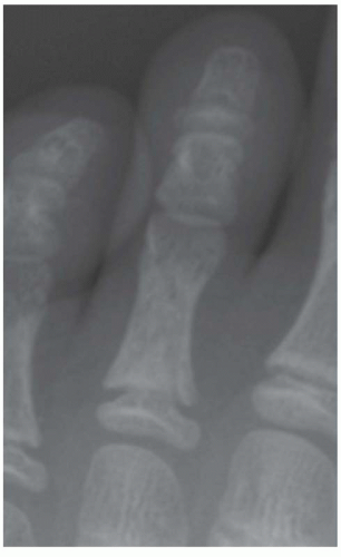 Figure 22.8. Phalangeal view demonstrating classical coned epiphysis. |
Fractures of the talar body involving the trochlea (dome) may be obvious in one projection and subtle in the other (Fig. 22.10). Fractures of the lateral and posterior talar processes are usually avulsion fractures associated with ankle injuries (Fig. 22.11).
Talar neck fractures usually occur with only minimal displacement, and CT is frequently useful in demonstrating or confirming subtle fractures and their fragment alignment. These are described according to the Hawkin’s classification (Fig. 22.12).15 This system is based on the number of associated dislocations at the ankle, subtalar, and talonavicular joints. This has significant prognostic value because
talar neck fractures are associated with avascular necrosis due to their distal to proximal blood supply; the greater the number of associated dislocations, the higher the risk of avascular necrosis.
talar neck fractures are associated with avascular necrosis due to their distal to proximal blood supply; the greater the number of associated dislocations, the higher the risk of avascular necrosis.
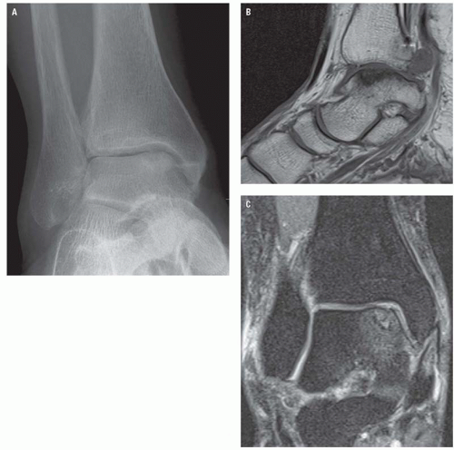 Figure 22.9. A: AP ankle view showing medial talar dome osteochondral fracture. B: Sagittal T1W view showing the full extent of the injury. C: Coronal short-tau inversion recovery (STIR) image showing the associated edema. |
Calcaneal Injuries
The calcaneus is the most commonly fractured tarsal bone and accounts for about 1% to 2% of all fractures.16 Fractures are usually the result from axial loading, with the downward force of the body transmitted through the talus, which acts as a wedge; crushing; and splitting the angle of the os calcis. Due to the mechanism of injury, calcaneal fractures are frequently bilateral and, in approximately 10% of cases, are associated with compression fractures of the thoracolumbar spine.17
Calcaneal fractures have characteristic appearances based on the mechanism of injury and are divided into two major categories: intra-articular and extraarticular. Approximately 75% are intraarticular, producing typical features including loss of height due to impaction and rotation of the tuberosity fragment, increase in width due to lateral displacement of the tuberosity fragment, and disruption of
the posterior facet of the subtalar joint.18 They are thus readily apparent in both lateral and axial projections.
the posterior facet of the subtalar joint.18 They are thus readily apparent in both lateral and axial projections.
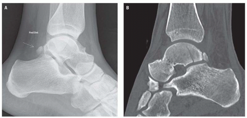 Figure 22.10. A: Lateral ankle radiograph that has unhelpfully had the normal os trigonum labeled as pathologic. Careful review of the radiograph shows the fracture through the talar body. B: Sagittal CT reformat unequivocally shows the fracture line. |
Depression of the posterior facet produces flattening of Bohler angle; however, because the normal range is from 20 to 40 degrees, it is not totally reliable as an indicator of depressed calcaneal fractures (Fig. 22.6). Calcaneal fractures that may be subtle in the lateral projection are usually readily substantiated in the axial projection because of either impaction or comminution.
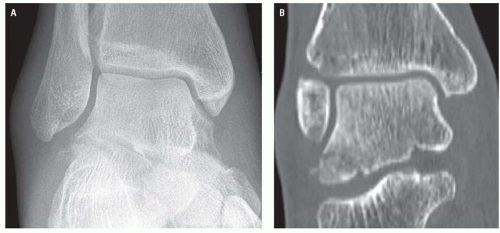 Figure 22.11. A: AP ankle radiograph showing subtle cortical irregularity to the lateral talar process. B: Coronal reformat showing the true extent of the lateral process fracture. |
Accurate description of calcaneal fractures including position and displacement of fracture fragments has significant implications for their management. CT is now routinely indicated in their


Related posts:
Stay updated, free articles. Join our Telegram channel
Full access? Get Clinical Tree
