GENERAL CONSIDERATIONS
The knee is probably more commonly injured than any other joint of the body and is the most vulnerable joint from the standpoint of athletic injury. Extensive soft tissue damage may exist without a recognizable radiographic sign. Thus, a normal-appearing radiographic examination of the knee does not exclude the possibility of significant injury to the ligaments surrounding, or within, the knee joint. Magnetic resonance imaging (MRI) is the imaging modality of choice in the diagnosis of acute (and chronic) soft tissue, chondral, and occult skeletal injuries of the knee. However, because the definitive evaluation and management of patients with soft tissue and occult skeletal injuries of the knee are not within the purview of emergent care and because MRI is currently not a generally accepted part of the emergency imaging of the appendicular skeleton, the reader is referred to the cited references.
The use of multidetector computed tomography (MDCT) is useful in the search of undisplaced fractures and is now an integral in the evaluation of traumatized knees, especially in the depiction of complex fracture anatomy. MDCT provides fast-volume imaging, multiplanar reconstructions (MPRs) with near isotropic viewing, threedimensional (3-D) images, and thick-slice (wedge) MPRs, which offer surgeons a detailed road map for preoperative planning. Computed tomography (CT) has also allowed for grading of trauma in knees especially in tibial plateau type fractures (Schatzker classification), permitting patients to be managed more effectively. The potential benefits and disadvantages of MDCT over plain radiography are summarized in
Table 20.1.
In children, particularly, pain caused by an abnormality of the hip may be referred to the knee. It is important that the hip be specifically examined when a child complains of knee pain that seems to be disproportionate to the clinical and radiographic evaluation of the knee or if a young child refuses to bear weight on one leg. In adults, a nontraumatic swollen, hot, tender knee should prompt consideration of bacterial pyarthrosis.
GENERAL ANATOMY OF THE KNEE JOINT
Key radiologic anatomy pertinent to interpretation of trauma radiographs is summarized in the next paragraphs.
The Femur
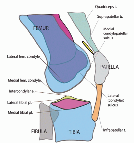
The distal femur is composed of two bulbous bony projections: The medial and lateral femoral condyles. On the sagittal projection or lateral radiograph, the medial condyle can be discerned from the lateral condyle by its morphology (
Figs. 20.1 and
20.2); the medial condyle is larger and has a convex articular surface. Both femoral condyles contain condylopatellar sulci, minor indentations that divide the condyles in a sagittal oblique plane.
The medial condylopatellar sulcus divides the condyle into an anterior one-third and a posterior twothird segment. The lateral condylopatellar sulcus divides the condyle into two approximate halves. Aside from these minor indentations, the condyles should be smooth.
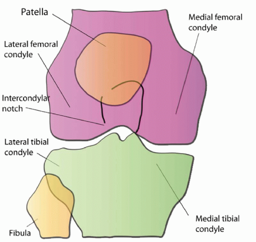
The medial and lateral condyles are separated inferiorly by the intercondylar notch (
Figs. 20.3 and
20.4).
The Tibia
On the lateral projection, the medial tibial plateau is concave medially with a pointed dorsal corner (
Fig. 20.5; see also
Figs. 20.3 and
20.4 for accompanying frontal projection). The lateral tibial plateau is relatively flat with a rounded dorsal corner. Disruption to these contours should raise the suspicion for a fracture.
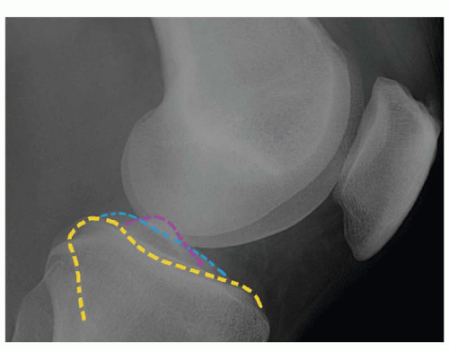
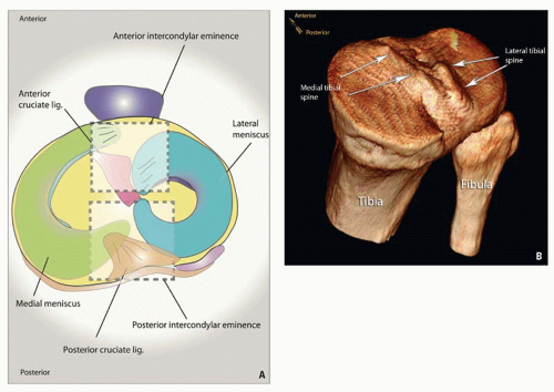
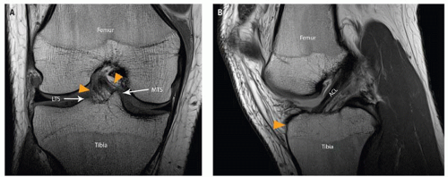
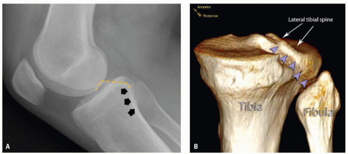
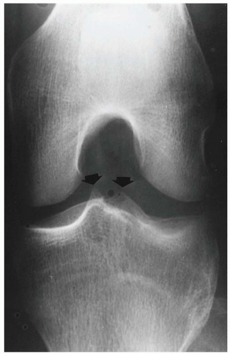
The medial and lateral tibial plateaus are separated by an intercondylar eminence (
Fig. 20.6). The intercondylar eminence is devoid of cartilage and mainly serves as a footprint for ligamentous attachments. It is a triangular area with a base anteriorly and an apex posteriorly. Posteriorly near the apex arise two bony projections: The slightly anterior medial and a posterior lateral tibial spines/tubercles/eminences (
Fig. 20.6). The anterior intercondylar eminence serves as the root attachments for the anterior medial and lateral menisci and footprint for the anterior cruciate ligament (ACL). The posterior intercondylar eminence functions as root attachments for the posterior medial and lateral menisci and the footprint for the posterior cruciate ligament (PCL). The medial tibial spine is more anterior than its lateral counterpart and can be discerned on the lateral radiograph.
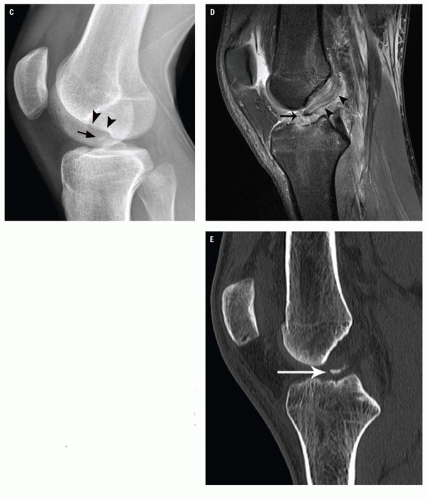
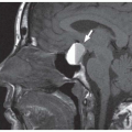
The ACL inserts between the medial and lateral tibial spines, 10 to 14 mm behind the anterior border of the tibia (
Fig. 20.7). Presence of an anteriorly placed bony fragment in the intercondylar notch is suspicious for distal ACL avulsion (
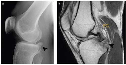
Fig. 20.7C). The PCL attaches in a depression between the two tibial plateaus dorsally. Focal discontinuity of the posterior tibial plateau articular surface should suggest distal PCL avulsion (
Fig. 20.8).
The anterior tibial tubercle is a bony protuberance located on the anterior aspect of the proximal tibia. It acts as the distal attachment for the infrapatellar tendon.
Gerdy tubercle is a bony protuberance at the anterior lateral tibial condyle, serving as the distal attachment for the iliotibial band (ITB).
The Fibula
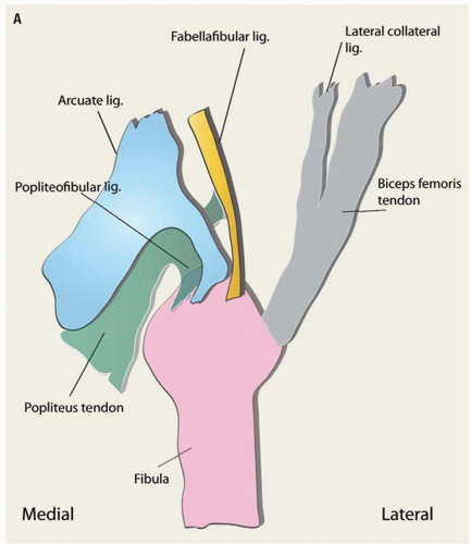
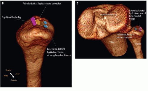
The proximal fibula comprises a head and styloid process that act as attachment sites for posterolateral corner structures of the knee (
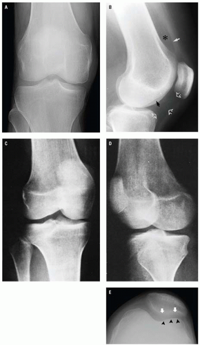
Fig. 20.9). The styloid process is the pointed aspect of the fibula head. Knowledge of anatomical ligamentous attachment landmarks can help the reader discern the type of ligamentous injury that has occurred. The posterosuperior medial facet of the fibular styloid process is occupied by the popliteofibular ligament attachment. The fibular styloid process/fibular head apex serves as the distal attachment for the arcuate, fabellofibular, and popliteofibular ligaments, collectively known as the arcuate complex. The arcuate ligament is deep to that of the fabellofibular ligament. The fabellofibular ligament insertion lies medial to the direct arm of the short head of biceps femoris (not shown). The lateral collateral ligament and long head of biceps femoris are further lateral and are attached to the lateral margin of the fibular head.
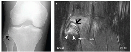
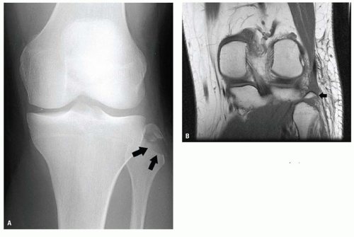
Identification of an avulsion fracture of the fibular head is important because it may ref lect injury to the arcuate complex (
Figs. 20.10 and
20.11). Such injuries may lead to posterolateral instability, characterized clinically by posterior subluxation and external rotation of the tibial plateau relative to the femur. Failure to recognize this type of injury may cause chronic instability and failure of cruciate ligament reconstruction.
The Proximal Tibiofibular Joint
The proximal tibiofibular joint is the articulation of the lateral tibial condyle and the fibula head, located posterolaterally in relation to the tibia. Bound by a joint capsule and connected via anterior and posterior ligaments, the relationship between the tibia and fibula should be constant. Overcoverage or undercoverage of the fibula head on anteroposterior (AP) radiographs should raise the suspicion of proximal tibiofibular joint dislocation. A useful landmark in identifying the correct position of the fibula head and in excluding proximal tibiofibular joint dislocation or subluxation is the posterior tibial groove. The posterior tibial groove, located posteromedially within the lateral tibial condyle, can be recognized by following the lateral tibial spine inferiorly along the posterior aspect of the tibia on the lateral radiograph. Radiographically, this can be seen as an oblique radiodense line. On lateral projections, this line should intersect the fibula head (
Fig. 20.12). Anterior and lateral deviation of the fibula head on lateral and AP radiographs respectively signify anterolateral dislocation, whereas posterior and medial deviation of the fibula on lateral and AP radiographs respectively indicate posteromedial dislocation.
The Patella
The patella (
Figs. 20.1,
20.2,
20.3,
20.4 and
20.13) is the largest sesamoid bone in the human body, lying within the substance of the quadriceps mechanism. This flat, triangular structure, with a distal apex, articulates with the trochlear groove of the femur.
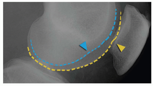
The patella has two main surfaces or facets: The medial and lateral facets, separated by a central ridge. Knowledge of patella facetal morphology can aid orientation. There are three main variations of patella morphology, that is, Wiberg types I to III (
Table 20.2).
The most common patella morphology is the Wiberg type II patella (
Fig. 20.13). On the axial plane, the lateral facet is generally flatter, wider, and deeper than its medial counterpart. The medial
facet can be easily recognized; it contains a vertical bridge that divides it from a smaller, more medial “odd” facet. The odd facet only contacts the femoral condyle in flexion.
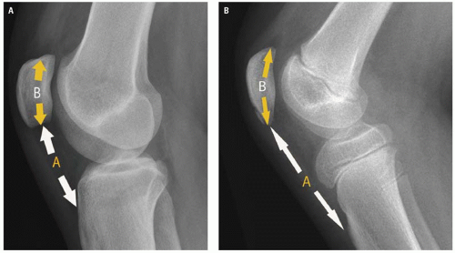
With the knee slightly flexed, the craniocaudal patella tendon length should be equal to the length of the craniocaudal length of the patella (Insall-Salvati ratio) (
Fig. 20.14A). Variation in this ratio of up to 0.2 is acceptable but beyond this, one should suspect injury to the extensor mechanism, especially when there is a relevant clinical history and soft tissue swelling. In particular, if the apparent patella tendon length is 20% more than that of the bony patella (patella alta, high-riding patella) (
Fig. 20.14B), a patella tendon rupture should be assumed. Conversely, for the reversed scenario with patella baja (low-riding patella), then a quadriceps tendon rupture is suspected.
RADIOGRAPHIC ANATOMY ACCORDING TO PROJECTION
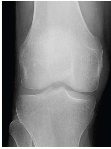
The radiographic anatomy of the normal adult knee is seen in
Figure 20.15. In the frontal projection (
Fig. 20.15A), the patella is obscured by the density of the superimposed intercondylar portion of the femur. Therefore, the AP projection of the knee usually has little significance in the evaluation of the patella. The medial and lateral intercondylar spines are well seen within the concavity of the intercondylar notch of the femur (
Fig. 20.3). On a properly positioned frontal projection of the knee made with the central beam passing approximately 1 cm inferior to the inferior pole of the patella, the medial and lateral compartments of the joint space and the contiguous surfaces of the femoral condyles and the tibial plateau are clearly demonstrated.
In the true lateral projection (
Fig. 20.15B), the articulating surface of the femoral condyles should be closely superimposed and the patellofemoral space clearly evident. The suprapatellar recess of the joint space should be easily identified on a properly exposed lateral radiograph. The infrapatellar portion of the joint space, lying anterior and inferior to the femoral condyles, should be visible as a rectangular area of relative radiolucency (Hoffa fat pad).
External (
Fig. 20.15C) and internal (
Fig. 20.15D) oblique projections provide a perspective of the femoral condyles and tibial tuberosities not visible on the straight frontal and lateral projections. Additionally, the patella is partially projected free of the femur, making possible the evaluation of its medial and lateral margins.
The axial (tangential, “sunrise”) view of the patella is seen in
Figure 20.15E. In this projection, the patellofemoral compartment and the posterior surface of the patella are well delineated. The medial femoral condyle is larger and more prominent than the lateral, and the slope of the smaller medial facet of the posterior surface of the patella is steeper than that of the larger lateral facet. This is the anatomic basis for the fact that dislocation of the patella practically always occurs laterally. The axial projection may be obtained with the patient either prone or supine. In either event, the leg is flexed on the thigh approximately 45 degrees, and the central x-ray beam is directed posterior to the patella through the patellofemoral compartment.